US8077885B2 - Microphone device - Google Patents
Microphone device Download PDFInfo
- Publication number
- US8077885B2 US8077885B2 US12/501,565 US50156509A US8077885B2 US 8077885 B2 US8077885 B2 US 8077885B2 US 50156509 A US50156509 A US 50156509A US 8077885 B2 US8077885 B2 US 8077885B2
- Authority
- US
- United States
- Prior art keywords
- aperture
- microphone device
- supporter
- bottom portion
- optical sensor
- Prior art date
- Legal status (The legal status is an assumption and is not a legal conclusion. Google has not performed a legal analysis and makes no representation as to the accuracy of the status listed.)
- Expired - Fee Related, expires
Links
Images


Classifications
-
- H—ELECTRICITY
- H04—ELECTRIC COMMUNICATION TECHNIQUE
- H04R—LOUDSPEAKERS, MICROPHONES, GRAMOPHONE PICK-UPS OR LIKE ACOUSTIC ELECTROMECHANICAL TRANSDUCERS; ELECTRIC HEARING AIDS; PUBLIC ADDRESS SYSTEMS
- H04R23/00—Transducers other than those covered by groups H04R9/00 - H04R21/00
- H04R23/008—Transducers other than those covered by groups H04R9/00 - H04R21/00 using optical signals for detecting or generating sound
-
- H—ELECTRICITY
- H04—ELECTRIC COMMUNICATION TECHNIQUE
- H04R—LOUDSPEAKERS, MICROPHONES, GRAMOPHONE PICK-UPS OR LIKE ACOUSTIC ELECTROMECHANICAL TRANSDUCERS; ELECTRIC HEARING AIDS; PUBLIC ADDRESS SYSTEMS
- H04R2499/00—Aspects covered by H04R or H04S not otherwise provided for in their subgroups
- H04R2499/10—General applications
- H04R2499/11—Transducers incorporated or for use in hand-held devices, e.g. mobile phones, PDA's, camera's
Definitions
- the disclosure relates to a microphone device.
- various microphones are used in many applications, such as telephones, tape recorders and cell phones, for example.
- a typical microphone device includes a light emitting unit, a light receiving unit and a vibrating membrane.
- the light emitting unit emits light beams to the vibrating membrane, and then the vibrating membrane reflects the light beams to the light receiving unit.
- the vibrating membrane moves back and forth in response to the sound wave to vary incident angles of the light beams, such that the amount of light beams collected by the light receiving unit varies correspondingly.
- the light receiving unit generates an electrical signal via detecting the varying of the amount of collected light beams. Finally, the electrical signal is processed and converted into an audio signal.
- a nontransparent plate is positioned between the light emitting unit and the light receiving unit, however, such structure complicates the structure of the typical microphone device.
- FIG. 1 is a cross-sectional view of one embodiment of a microphone device, the microphone device including a cover and a vibrating membrane.
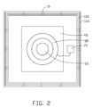
- FIG. 2 is a perspective view of the microphone device of FIG. 1 , the cover and the vibrating membrane being removed.
- a microphone device 100 includes an enclosure 10 , a cover 12 , a light source 20 , a vibrating membrane 30 , a supporter 40 , an optical sensor 50 , a lens 60 and a processing unit 70 .
- the enclosure 10 has a bottom portion 102 and a sidewall 104 extending from the bottom portion 102 .
- An opening 11 is defined in the enclosure 10 and opposite to the bottom portion 102 .
- a plurality of through holes 15 is defined in the sidewall 104 and configured to balance sound pressure.
- a protrusion 106 extends from a topmost portion of the sidewall 104 .
- the enclosure 10 may be rectangular-shaped or cylindrical-shaped. In the illustrated embodiment, the enclosure 10 is substantially rectangular-shaped.
- the supporter 40 is enclosed in the enclosure 10 and positioned on the bottom portion 102 .
- the supporter 40 is comprised of a nontransparent material.
- a frustoconical-shaped passage 41 is defined in a center portion of the supporter 40 .
- the passage 41 has a wide aperture 410 and a narrow aperture 412 at two opposite ends.
- the wide aperture 410 is adjacent to the bottom portion 102 .
- the supporter 40 may be rectangular-shaped or cylindrical-shaped. In the illustrated embodiment, the supporter 40 is substantially rectangular-shaped.
- the light source 20 is secured on the bottom portion 102 and received in the passage 41 .
- the light source 20 is configured to emit light beams to the lens 60 .
- the light source 20 may include a light emitting diode or a laser. In the illustrated embodiment, the light source 20 includes a laser.
- the optical sensor 50 is positioned on the supporter 40 and adjacent to the narrower aperture 412 .
- the optical sensor 50 is substantially annular-shaped and has an inner diameter greater than a diameter of the narrower aperture 412 .
- the lens 60 is partially received in the optical sensor 50 and positioned on the supporter 40 to cover the narrower aperture 412 .
- the lens 60 is substantially semi-spherical-shaped, and coaxial with the optical sensor 50 and the passage 41 .
- the lens 60 has a convex surface 62 configured to diverge the light beams to the vibrating membrane 30 .
- a diameter of the lens 60 is smaller than the inner diameter of the optical sensor 50 and slightly greater than a diameter of the narrower aperture 412 .
- a peripheral portion of the vibrating membrane 30 contacts the protrusion 106 , such that the vibrating membrane 30 is supported on the sidewall 104 and covers the opening 11 .
- the vibrating membrane 30 further defines a reflective surface 301 facing the convex surface 62 and the optical sensor 60 .
- the reflective surface 301 is configured to reflect light beams refracted and diverged by the convex surface 62 to the optical sensor 50 .
- a projecting portion 120 extends from a peripheral portion of the cover 12 .
- the peripheral portion of the vibrating membrane 30 is clipped between the projecting portion 120 and the protrusion 106 , such that the vibrating membrane 30 can seal the opening 11 .
- a plurality of sound holes 13 is defined in the central portion of the cover 12 and configured to allow a sound wave to pass through.
- the processing unit 70 is positioned in the enclosure 10 and electrically coupled to the optical sensor 50 .
- the processing unit 70 may be a digital signal processing unit.
- the light source 20 emits light beams to the lens 60 .
- the light beams transmit through the lens 60 , and then are refracted and diverged by the convex surface 62 to the reflective surface 301 . Diverged light beams are reflected by the reflective surface 301 to the optical sensor 60 .
- the vibrating membrane 30 vibrates in response to the sound wave such that incident angles of the diverged light beams vary.
- the amount of light beams collected by the optical sensor 50 varies in response to the vibrating of the vibrating membrane 30 .
- the optical sensor 50 detects the varying of the amount of the collected light beams to generate a corresponding electrical signal.
- the electrical signal is delivered to the processing unit 70 , and converted by the processing unit 70 into an audio signal.
- the nontransparent supporter 40 is applied to block light beams emitted from the light source 20 from transmitting to the optical sensor 50 directly, allowing the microphone device 10 to have a compact structure.
Landscapes
- Physics & Mathematics (AREA)
- Engineering & Computer Science (AREA)
- Acoustics & Sound (AREA)
- Signal Processing (AREA)
- Electrostatic, Electromagnetic, Magneto- Strictive, And Variable-Resistance Transducers (AREA)
Abstract
Description
Claims (11)
Applications Claiming Priority (3)
| Application Number | Priority Date | Filing Date | Title |
|---|---|---|---|
| CN200810303590.X | 2008-08-08 | ||
| CN200810303590 | 2008-08-08 | ||
| CN200810303590A CN101646121A (en) | 2008-08-08 | 2008-08-08 | Microphone module |
Publications (2)
| Publication Number | Publication Date |
|---|---|
| US20100034413A1 US20100034413A1 (en) | 2010-02-11 |
| US8077885B2 true US8077885B2 (en) | 2011-12-13 |
Family
ID=41652999
Family Applications (1)
| Application Number | Title | Priority Date | Filing Date |
|---|---|---|---|
| US12/501,565 Expired - Fee Related US8077885B2 (en) | 2008-08-08 | 2009-07-13 | Microphone device |
Country Status (2)
| Country | Link |
|---|---|
| US (1) | US8077885B2 (en) |
| CN (1) | CN101646121A (en) |
Families Citing this family (4)
| Publication number | Priority date | Publication date | Assignee | Title |
|---|---|---|---|---|
| US20140064530A1 (en) * | 2011-03-17 | 2014-03-06 | Advanced Bionics Ag | Implantable microphone |
| EP2958340A1 (en) * | 2014-06-17 | 2015-12-23 | Thomson Licensing | Optical microphone and method using the same |
| CN108989919B (en) * | 2018-07-13 | 2020-09-22 | 潍坊歌尔微电子有限公司 | a sensor |
| CN111263283A (en) * | 2020-02-17 | 2020-06-09 | 瑞声声学科技(深圳)有限公司 | Optical microphone |
Citations (3)
| Publication number | Priority date | Publication date | Assignee | Title |
|---|---|---|---|---|
| US4422182A (en) * | 1981-03-12 | 1983-12-20 | Olympus Optical Co. Ltd. | Digital microphone |
| US5262884A (en) * | 1991-10-09 | 1993-11-16 | Micro-Optics Technologies, Inc. | Optical microphone with vibrating optical element |
| US5621806A (en) * | 1992-02-14 | 1997-04-15 | Texas Instruments Incorporated | Apparatus and methods for determining the relative displacement of an object |
Family Cites Families (2)
| Publication number | Priority date | Publication date | Assignee | Title |
|---|---|---|---|---|
| US7391976B2 (en) * | 1999-12-13 | 2008-06-24 | Kabushiki Kaisha Kenwood | Optical acoustoelectric transducer |
| JP3887535B2 (en) * | 2000-12-19 | 2007-02-28 | 株式会社ケンウッド | Acoustoelectric converter |
-
2008
- 2008-08-08 CN CN200810303590A patent/CN101646121A/en active Pending
-
2009
- 2009-07-13 US US12/501,565 patent/US8077885B2/en not_active Expired - Fee Related
Patent Citations (3)
| Publication number | Priority date | Publication date | Assignee | Title |
|---|---|---|---|---|
| US4422182A (en) * | 1981-03-12 | 1983-12-20 | Olympus Optical Co. Ltd. | Digital microphone |
| US5262884A (en) * | 1991-10-09 | 1993-11-16 | Micro-Optics Technologies, Inc. | Optical microphone with vibrating optical element |
| US5621806A (en) * | 1992-02-14 | 1997-04-15 | Texas Instruments Incorporated | Apparatus and methods for determining the relative displacement of an object |
Also Published As
| Publication number | Publication date |
|---|---|
| US20100034413A1 (en) | 2010-02-11 |
| CN101646121A (en) | 2010-02-10 |
Similar Documents
| Publication | Publication Date | Title |
|---|---|---|
| AU2014203876B2 (en) | Waterproof case | |
| US9795044B2 (en) | Waterproof case | |
| US9046415B2 (en) | Virtual detector for sensor system | |
| US8077885B2 (en) | Microphone device | |
| KR20210082566A (en) | Protective member for acoustic component and waterproof case | |
| JPWO2005069586A1 (en) | Mobile phone using bone conduction device | |
| US20010005272A1 (en) | Optically actuated transducer system | |
| US20170013334A1 (en) | Mobile terminal | |
| US20250016509A1 (en) | Device for sensing a motion of a deflective surface | |
| US9716949B2 (en) | Panel-form loudspeaker | |
| US9438986B2 (en) | In-ear headphone with sound pick-up capability | |
| CN102427573A (en) | Real-time voice signal pickup device based on self-mixing interference measurement method | |
| US20100111345A1 (en) | Miniature stylish noise and wind canceling microphone housing, providing enchanced speech recognition performance for wirless headsets | |
| KR20030017628A (en) | Device for detecting pressure fluctuations, display device, recording device and sound reproduction system | |
| US8032195B2 (en) | Portable device, acoustic component disposition method and acoustic component assembly | |
| US6906807B2 (en) | Membrane type optical transducers particularly useful as optical microphones | |
| KR101455076B1 (en) | Receiver with proximity and illuminance sensor | |
| US20100111346A1 (en) | Electronic device incorporating sound receiving member and method of manufacturing the same | |
| CN113170265A (en) | MEMS microphone assembly and method of manufacturing MEMS microphone assembly | |
| JP5190033B2 (en) | Vibration sensor | |
| JP2001157298A (en) | Optical microphone and its manufacturing method | |
| US10621967B2 (en) | Ultrasonic lens for receiver application | |
| CN220858142U (en) | An electronic device | |
| KR20030010652A (en) | Voice communication system having function of preventing speaker's voice waves from being spreaded out around him | |
| JP6550602B2 (en) | Optical microphone |
Legal Events
| Date | Code | Title | Description |
|---|---|---|---|
| AS | Assignment |
Owner name: HON HAI PRECISION INDUSTRY CO., LTD.,TAIWAN Free format text: ASSIGNMENT OF ASSIGNORS INTEREST;ASSIGNOR:CHANG, JEN-TSORNG;REEL/FRAME:022944/0712 Effective date: 20090708 Owner name: HON HAI PRECISION INDUSTRY CO., LTD., TAIWAN Free format text: ASSIGNMENT OF ASSIGNORS INTEREST;ASSIGNOR:CHANG, JEN-TSORNG;REEL/FRAME:022944/0712 Effective date: 20090708 |
|
| STCF | Information on status: patent grant |
Free format text: PATENTED CASE |
|
| FPAY | Fee payment |
Year of fee payment: 4 |
|
| FEPP | Fee payment procedure |
Free format text: MAINTENANCE FEE REMINDER MAILED (ORIGINAL EVENT CODE: REM.); ENTITY STATUS OF PATENT OWNER: LARGE ENTITY |
|
| LAPS | Lapse for failure to pay maintenance fees |
Free format text: PATENT EXPIRED FOR FAILURE TO PAY MAINTENANCE FEES (ORIGINAL EVENT CODE: EXP.); ENTITY STATUS OF PATENT OWNER: LARGE ENTITY |
|
| STCH | Information on status: patent discontinuation |
Free format text: PATENT EXPIRED DUE TO NONPAYMENT OF MAINTENANCE FEES UNDER 37 CFR 1.362 |
|
| FP | Lapsed due to failure to pay maintenance fee |
Effective date: 20191213 |