US8076750B1 - Linearity improvements of semiconductor substrate based radio frequency devices - Google Patents
Linearity improvements of semiconductor substrate based radio frequency devices Download PDFInfo
- Publication number
- US8076750B1 US8076750B1 US12/958,494 US95849410A US8076750B1 US 8076750 B1 US8076750 B1 US 8076750B1 US 95849410 A US95849410 A US 95849410A US 8076750 B1 US8076750 B1 US 8076750B1
- Authority
- US
- United States
- Prior art keywords
- layer
- trap
- silicon
- silicon substrate
- substrate
- Prior art date
- Legal status (The legal status is an assumption and is not a legal conclusion. Google has not performed a legal analysis and makes no representation as to the accuracy of the status listed.)
- Active
Links
Images


Classifications
-
- H—ELECTRICITY
- H01—ELECTRIC ELEMENTS
- H01L—SEMICONDUCTOR DEVICES NOT COVERED BY CLASS H10
- H01L23/00—Details of semiconductor or other solid state devices
- H01L23/58—Structural electrical arrangements for semiconductor devices not otherwise provided for, e.g. in combination with batteries
- H01L23/64—Impedance arrangements
- H01L23/645—Inductive arrangements
-
- H—ELECTRICITY
- H01—ELECTRIC ELEMENTS
- H01L—SEMICONDUCTOR DEVICES NOT COVERED BY CLASS H10
- H01L23/00—Details of semiconductor or other solid state devices
- H01L23/58—Structural electrical arrangements for semiconductor devices not otherwise provided for, e.g. in combination with batteries
- H01L23/64—Impedance arrangements
- H01L23/66—High-frequency adaptations
-
- H—ELECTRICITY
- H01—ELECTRIC ELEMENTS
- H01L—SEMICONDUCTOR DEVICES NOT COVERED BY CLASS H10
- H01L23/00—Details of semiconductor or other solid state devices
- H01L23/52—Arrangements for conducting electric current within the device in operation from one component to another, i.e. interconnections, e.g. wires, lead frames
- H01L23/522—Arrangements for conducting electric current within the device in operation from one component to another, i.e. interconnections, e.g. wires, lead frames including external interconnections consisting of a multilayer structure of conductive and insulating layers inseparably formed on the semiconductor body
- H01L23/5227—Inductive arrangements or effects of, or between, wiring layers
-
- H—ELECTRICITY
- H01—ELECTRIC ELEMENTS
- H01L—SEMICONDUCTOR DEVICES NOT COVERED BY CLASS H10
- H01L23/00—Details of semiconductor or other solid state devices
- H01L23/552—Protection against radiation, e.g. light or electromagnetic waves
-
- H—ELECTRICITY
- H01—ELECTRIC ELEMENTS
- H01L—SEMICONDUCTOR DEVICES NOT COVERED BY CLASS H10
- H01L2924/00—Indexing scheme for arrangements or methods for connecting or disconnecting semiconductor or solid-state bodies as covered by H01L24/00
- H01L2924/0001—Technical content checked by a classifier
- H01L2924/0002—Not covered by any one of groups H01L24/00, H01L24/00 and H01L2224/00
Definitions
- Embodiments of the present invention relate to Silicon substrates used to manufacture semiconductor devices, which may be used in radio frequency (RF) communications systems.
- RF radio frequency
- Silicon substrates are widely used in the manufacture of semiconductor devices. Low cost and highly evolved manufacturing techniques make Silicon a preferred material in many applications, when compared with other semiconductor materials. High resistivity Silicon substrates may be used in radio frequency (RF) devices. If the period of an RF signal is shorter than a majority carrier relaxation time, then the majority carriers in a Silicon substrate may not respond to the RF signal. The majority carriers may appear to be frozen and the Silicon substrate may behave as a dielectric. However, Silicon has certain characteristics that may produce undesirable behavior in some RF applications.
- RF radio frequency
- the doping level in high resistivity Silicon is very low or non-existent; therefore, oxide charges at the surface of a Silicon substrate, or a weak electric field in the Silicon substrate can induce an inversion or accumulation layer, which may function as a surface conduction layer at the surface of the Silicon substrate.
- RF signals traversing above the surface of the Silicon substrate may modulate the surface conduction layer, which may cause non-linear capacitance, non-linear conductance, or both affecting RF interactions between the Silicon substrate and other layers.
- the non-linear characteristics may introduce harmonic distortion in the RF signals, which may exceed allowable limits.
- One technique for reducing the impact of the non-linear characteristics is to incorporate a conductive shielding layer between the surface of the Silicon substrate and other layers handling RF signals; however, the conductive shielding layer may increase complexity and signal loss. Thus, there is a need to reduce, or eliminate, non-linear characteristics associated with a surface conduction layer without using a conductive shielding layer.
- the present invention relates to using a trap-rich layer, such as a polycrystalline Silicon layer, over a semiconductor substrate to substantially immobilize a surface conduction layer at the surface of the semiconductor substrate at radio frequency (RF) frequencies.
- the trap-rich layer may have a high density of traps that trap carriers from the surface conduction layer. The average release time from the traps may be longer than the period of any present RF signals, thereby effectively immobilizing the surface conduction layer, which may substantially prevent capacitance and inductance changes due to the RF signals. Therefore, harmonic distortion of the RF signals may be significantly reduced or eliminated.
- the semiconductor substrate may be a Silicon substrate, a Gallium Arsenide substrate, or another substrate.
- a metallization layer may be applied directly to the trap-rich layer.
- Other embodiments of the present invention may include one or more intervening layers between the trap-rich layer and the metallization layer.
- the metallization layer may be used to form an RF inductive element, an RF coupler, a micro-electromechanicalsystems (MEMS) RF device, such as a MEMS RF switch, or any combination thereof.
- MEMS micro-electromechanicalsystems
- an insulator layer may be located between the trap-rich layer and the metallization layer.
- the trap-rich layer may be included in a Silicon-on-insulator (SOI) wafer.
- SOI Silicon-on-insulator
- the SOI wafer may include the semiconductor substrate, the trap-rich layer may be formed over the semiconductor substrate, an insulator layer may be formed over the trap-rich layer, and an SOI device layer may be formed over the insulator layer.
- the SOI wafer may provide an RF transistor element, a MEMS RF device, such as a MEMS RF filter, or both.
- the semiconductor substrate may be a Silicon substrate, a Gallium Arsenide substrate, or another substrate.
- FIG. 1 shows a first semiconductor wafer, according to one embodiment of the present invention.
- FIG. 2 shows a radio frequency (RF) inductive element provided by the first semiconductor wafer illustrated in FIG. 1 .
- RF radio frequency
- FIG. 3 shows an RF coupler provided by the first semiconductor wafer illustrated in FIG. 1 .
- FIG. 4 shows a micro-electromechanical systems (MEMS) RF switch provided by the first semiconductor wafer illustrated in FIG. 1 .
- MEMS micro-electromechanical systems
- FIG. 5 shows a second semiconductor wafer, according to an alternate embodiment of the present invention.
- FIG. 6 shows an RF inductive element provided by the second semiconductor wafer illustrated in FIG. 5 .
- FIG. 7 shows an RF coupler provided by the second semiconductor wafer illustrated in FIG. 5 .
- FIG. 8 shows a MEMS RF switch provided by the second semiconductor wafer illustrated in FIG. 5 .
- FIG. 9 shows a Silicon-on-insulator (SOI) wafer, according to an additional embodiment of the present invention.
- FIG. 10 shows an RF transistor element provided by the SOI wafer illustrated in FIG. 9 .
- FIG. 11 shows a MEMS filter provided by the SOI wafer illustrated in FIG. 9 .
- FIG. 12 shows an application example of the present invention used in a mobile terminal.
- the present invention relates to using a trap-rich layer, such as a polycrystalline Silicon layer, over a semiconductor substrate to substantially immobilize a surface conduction layer at the surface of the semiconductor substrate at radio frequency (RF) frequencies.
- the trap-rich layer may have a high density of traps that trap carriers from the surface conduction layer. The average release time from the traps may be longer than the period of any present RF signals, thereby effectively immobilizing the surface conduction layer, which may substantially prevent capacitance and inductance changes due to the RF signals. Therefore, harmonic distortion of the RF signals may be significantly reduced or eliminated.
- the semiconductor substrate may be a Silicon substrate, a Gallium Arsenide substrate, or another substrate.
- the trap-rich layer is an amorphous Silicon film, which may be formed by modifying a top layer of a Silicon substrate to induce a large number of traps. Ions may be implanted to disrupt the Silicon lattice of the Silicon substrate to make it amorphous.
- a metallization layer may be applied directly to the trap-rich layer.
- Other embodiments of the present invention may include one or more intervening layers between the trap-rich layer and the metallization layer.
- the metallization layer may be used to form an RF inductive element, an RF coupler, a micro-electromechanical systems (MEMS) RF device, such as a MEMS RF switch, or any combination thereof.
- MEMS micro-electromechanical systems
- an insulator layer may be located between the trap-rich layer and the metallization layer.
- the trap-rich layer may be included in a Silicon-on-insulator (SOI) wafer.
- SOI Silicon-on-insulator
- the SOI wafer may include the semiconductor substrate, the trap-rich layer may be formed over the semiconductor substrate, an insulator layer may be formed over the trap-rich layer, and an SOI device layer may be formed over the insulator layer.
- the SOI wafer may provide an RF transistor element, a MEMS RF device, such as a MEMS RF filter, or both.
- the semiconductor substrate may be a Silicon substrate, a Gallium Arsenide substrate, or another substrate.
- FIG. 1 shows a side view of a first semiconductor wafer 10 , according to one embodiment of the present invention.
- the first semiconductor wafer 10 includes a Silicon substrate 12 .
- a polycrystalline Silicon layer 14 is formed over the Silicon substrate 12 .
- a layer using a different trap-rich material may be used instead of the polycrystalline Silicon layer 14 , according to alternate embodiments of the present invention.
- a metallization layer 16 is formed over the polycrystalline Silicon layer 14 .
- the polycrystalline Silicon layer 14 may have a high density of traps, which may be used to trap carriers from the Silicon substrate 12 , the polycrystalline Silicon layer 14 , or both. Trapping carriers may substantially immobilize a surface conduction layer (not shown) in the Silicon substrate 12 .
- the Silicon substrate 12 may or may not be doped.
- the Silicon substrate 12 may be doped to form N-type material, P-type material, or both.
- the polycrystalline Silicon layer 14 may or may not be doped.
- the polycrystalline Silicon layer 14 may be doped to form N-type material, P-type material, or both.
- the polycrystalline Silicon layer 14 may passivate the surface of the Silicon substrate 12 .
- a carrier concentration in the polycrystalline Silicon layer 14 may be less than a concentration of traps in the polycrystalline Silicon layer 14 .
- a thickness of the polycrystalline Silicon layer 14 may be greater than about 100 nanometers.
- An average release time of a carrier in a trap in the polycrystalline Silicon layer 14 may be greater than about 100 microseconds.
- the average release time of a carrier in a trap in the polycrystalline Silicon layer 14 is greater than about one millisecond.
- Other embodiments of the present invention may use another semiconductor substrate in place of the Silicon substrate 12 , such as Gallium Arsenide.
- the trap-rich layer is an amorphous Silicon film, which may be formed by modifying a top layer of the Silicon substrate 12 to induce a large number of traps. Ions may be implanted to disrupt the Silicon lattice of the Silicon substrate 12 to make it amorphous.
- the polycrystalline Silicon layer 14 may be in electrical contact with the Silicon substrate 12 .
- the Silicon substrate 12 may have a thin oxide layer (not shown), which may have a thickness of less than about 20 angstroms and may be formed when the polycrystalline Silicon layer 14 is formed over the Silicon substrate 12 .
- the thin oxide layer may be formed based on the process technique used to add the polycrystalline Silicon layer 14 , such as low pressure chemical vapor deposition (LPCVD). However, the thin oxide layer would not normally interfere with carrier transfer between the polycrystalline Silicon layer 14 and the Silicon substrate 12 .
- the Silicon substrate 12 may have a majority carrier relaxation time, which may be about equal to a resistivity of the Silicon substrate 12 times a dielectric permittivity of the Silicon substrate 12 .
- the thickness of the polycrystalline Silicon layer 14 may be equal to about 300 nanometers.
- the resistivity of the Silicon substrate 12 may be greater than about 1000 ohm centimeters.
- the dielectric permittivity of the Silicon substrate 12 may be equal to about one picofarad per centimeter.
- the majority carrier relaxation time of the Silicon substrate 12 may be equal to about one nanosecond.
- Alternate embodiments of the present invention may include one or more intervening layers between the Silicon substrate 12 and the polycrystalline Silicon layer 14 , between the polycrystalline Silicon layer 14 and the metallization layer 16 , or both. However, any intervening layers between the Silicon substrate 12 and the polycrystalline Silicon layer 14 must not interfere with carrier transfer between the polycrystalline Silicon layer 14 and the Silicon substrate 12 .
- FIG. 2 shows a top view of an RF inductive element 18 provided by the first semiconductor wafer 10 illustrated in FIG. 1 .
- the RF inductive element 18 may be formed using the metallization layer 16 and may include a first inductive terminal 20 conductively coupled to a second inductive terminal 22 .
- the RF inductive element 18 may be associated with an RF signal, which may have an RF signal period that is less than or equal to the majority carrier relaxation time of the Silicon substrate 12 .
- the majority carrier relaxation time of the Silicon substrate 12 is equal to about one nanosecond and the RF signal period is less than or equal to about one nanosecond.
- FIG. 3 shows a top view of an RF coupler 24 provided by the first semiconductor wafer 10 illustrated in FIG. 1 .
- the RF coupler 24 may be formed using the metallization layer 16 and may include a first coupler terminal 26 conductively coupled to a second coupler terminal 28 , and a third coupler terminal 30 conductively coupled to a fourth coupler terminal 32 .
- the first and second coupler terminals 26 , 28 may be magnetically coupled to the third and fourth coupler terminals 30 , 32 .
- the RF coupler 24 may be associated with an RF signal, which may have an RF signal period that is less than or equal to the majority carrier relaxation time of the Silicon substrate 12 .
- the majority carrier relaxation time of the Silicon substrate 12 is equal to about one nanosecond and the RF signal period is less than or equal to about one nanosecond.
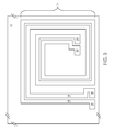
- FIG. 4 shows a top view of a MEMS RF switch 34 provided by the first semiconductor wafer 10 illustrated in FIG. 1 .
- the MEMS RF switch 34 may be formed using the metallization layer 16 and may include a first MEMS terminal 36 and a second MEMS terminal 38 .
- the MEMS RF switch 34 When the MEMS RF switch 34 is in a closed state, the first MEMS terminal 36 may be conductively coupled to the second MEMS terminal 38 .
- the MEMS RF switch 34 When the MEMS RF switch 34 is in an open state, the first MEMS terminal 36 may be electrically isolated from the second MEMS terminal 38 .
- the MEMS RF switch 34 may be associated with an RF signal, which may have an RF signal period that is less than or equal to the majority carrier relaxation time of the Silicon substrate 12 .
- the majority carrier relaxation time of the Silicon substrate 12 is equal to about one nanosecond and the RF signal period is less than or equal to about one nanosecond.
- Alternate embodiments of the present invention may provide other MEMS devices by the first semiconductor wafer 10 illustrated in FIG. 1 .
- the other MEMS devices may be formed using the metallization layer 16 .
- FIG. 5 shows a side view of a second semiconductor wafer 40 , according to an alternate embodiment of the present invention.
- An insulator layer 42 may be formed over the polycrystalline Silicon layer 14 , and the metallization layer 16 may be formed over the insulator layer 42 .
- a layer using a different trap-rich material may be used instead of the polycrystalline Silicon layer 14 , according to alternate embodiments of the present invention.
- the insulator layer 42 may include dielectric material.
- the insulator layer 42 includes Silicon Dioxide.
- the insulator layer 42 includes Silicon Nitride.
- Alternate embodiments of the present invention may include one or more intervening layers between the Silicon substrate 12 and the polycrystalline Silicon layer 14 , between the polycrystalline Silicon layer 14 and the insulator layer 42 , between the insulator layer 42 and the metallization layer 16 , or any combination thereof.
- any intervening layers between the Silicon substrate 12 and the polycrystalline Silicon layer 14 must not interfere with carrier transfer between the polycrystalline Silicon layer 14 and the Silicon substrate 12 .
- Other embodiments of the present invention may use another semiconductor substrate in place of the Silicon substrate 12 , such as Gallium Arsenide.
- the trap-rich layer is an amorphous Silicon film, which may be formed by modifying a top layer of the Silicon substrate 12 to induce a large number of traps. Ions may be implanted to disrupt the Silicon lattice of the Silicon substrate 12 to make it amorphous.
- FIG. 6 shows a top view of the RF inductive element 18 provided by the second semiconductor wafer 40 illustrated in FIG. 5 .
- the RF inductive element 18 may be formed using the metallization layer 16 and may include the first inductive terminal 20 conductively coupled to the second inductive terminal 22 .
- the RF inductive element 18 may be associated with an RF signal, which may have an RF signal period that is less than or equal to the majority carrier relaxation time of the Silicon substrate 12 .
- the majority carrier relaxation time of the Silicon substrate 12 is equal to about one nanosecond and the RF signal period is less than or equal to about one nanosecond.
- FIG. 7 shows a top view of the RF coupler 24 provided by the second semiconductor wafer 40 illustrated in FIG. 5 .
- the RF coupler 24 may be formed using the metallization layer 16 and may include the first coupler terminal 26 conductively coupled to the second coupler terminal 28 , and the third coupler terminal 30 conductively coupled to the fourth coupler terminal 32 .
- the first and second coupler terminals 26 , 28 may be magnetically coupled to the third and fourth coupler terminals 30 , 32 .
- the RF coupler 24 may be associated with an RF signal, which may have an RF signal period that is less than or equal to the majority carrier relaxation time of the Silicon substrate 12 . In an exemplary embodiment of the present invention, the majority carrier relaxation time of the Silicon substrate 12 is equal to about one nanosecond and the RF signal period is less than or equal to about one nanosecond.
- FIG. 8 shows a top view of the MEMS RF switch 34 provided by the second semiconductor wafer 40 illustrated in FIG. 5 .
- the MEMS RF switch 34 may be formed using the metallization layer 16 and may include the first MEMS terminal 36 and the second MEMS terminal 38 .
- the MEMS RF switch 34 When the MEMS RF switch 34 is in a closed state, the first MEMS terminal 36 may be conductively coupled to the second MEMS terminal 38 .
- the MEMS RF switch 34 When the MEMS RF switch 34 is in an open state, the first MEMS terminal 36 may be electrically isolated from the second MEMS terminal 38 .
- the MEMS RF switch 34 may be associated with an RF signal, which may have an RF signal period that is less than or equal to the majority carrier relaxation time of the Silicon substrate 12 .
- the majority carrier relaxation time of the Silicon substrate 12 is equal to about one nanosecond and the RF signal period is less than or equal to about one nanosecond.
- Alternate embodiments of the present invention may provide other MEMS devices by the second semiconductor wafer 40 illustrated in FIG. 5 .
- the other MEMS devices may be formed using the metallization layer 16 .
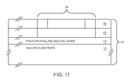
- FIG. 9 shows a side view of an SOI wafer 44 , according to an additional embodiment of the present invention.
- the SOI wafer 44 includes the Silicon substrate 12 .
- the polycrystalline Silicon layer 14 is formed over the Silicon substrate 12
- the insulator layer 42 is formed over the polycrystalline Silicon layer 14
- an SOI device layer 46 is formed over the insulator layer 42 .
- a layer using a different trap-rich material may be used instead of the polycrystalline Silicon layer 14 , according to alternate embodiments of the present invention.
- the insulator layer 42 may include dielectric material.
- the insulator layer 42 includes Silicon Dioxide.
- the insulator layer 42 includes Silicon Nitride.
- Alternate embodiments of the present invention may include one or more intervening layers between the Silicon substrate 12 and the polycrystalline Silicon layer 14 , between the polycrystalline Silicon layer 14 and the insulator layer 42 , between the insulator layer 42 and the SOI device layer 46 , or any combination thereof.
- any intervening layers between the Silicon substrate 12 and the polycrystalline Silicon layer 14 must not interfere with carrier transfer between the polycrystalline Silicon layer 14 and the Silicon substrate 12 .
- Other embodiments of the present invention may use another semiconductor substrate in place of the Silicon substrate 12 , such as Gallium Arsenide.
- the trap-rich layer is an amorphous Silicon film, which may be formed by modifying a top layer of the Silicon substrate 12 to induce a large number of traps. Ions may be implanted to disrupt the Silicon lattice of the Silicon substrate 12 to make it amorphous.
- FIG. 10 shows a side view of an RF transistor element 48 provided by the SOI wafer 44 illustrated in FIG. 9 .
- the RF transistor element 48 may be formed from the SOI device layer 46 and may include a field effect transistor (FET) element having a source 50 , a drain 52 , and a gate 54 that may be formed using doped areas of the SOI device layer 46 .
- FET field effect transistor
- the RF transistor element 48 may include a bipolar transistor element (not shown), a metal oxide semiconductor FET, or both.
- FIG. 11 shows a side view of a MEMS filter 56 provided by the SOI wafer 44 illustrated in FIG. 9 .
- the MEMS filter 56 may be formed from the SOI device layer 46 and may be used to filter RF signals. Alternate embodiments of the present invention may provide other MEMS devices by the SOI wafer 44 illustrated in FIG. 9 . The other MEMS devices may be formed using the SOI device layer 46 .
- the mobile terminal 58 may include a receiver front end 60 , a radio frequency transmitter section 62 , an antenna 64 , the MEMS RF switch 34 , a baseband processor 66 , a control system 68 , a frequency synthesizer 70 , and an interface 72 .
- the receiver front end 60 receives information bearing radio frequency signals from one or more remote transmitters provided by a base station (not shown).
- a low noise amplifier (LNA) 74 amplifies the signal.
- LNA low noise amplifier
- a filter circuit 76 minimizes broadband interference in the received signal, while down conversion and digitization circuitry 78 down converts the filtered, received signal to an intermediate or baseband frequency signal, which is then digitized into one or more digital streams.
- the receiver front end 60 typically uses one or more mixing frequencies generated by the frequency synthesizer 70 .
- the baseband processor 66 processes the digitized received signal to extract the information or data bits conveyed in the received signal. This processing typically comprises demodulation, decoding, and error correction operations. As such, the baseband processor 66 is generally implemented in one or more digital signal processors (DSPs).
- DSPs digital signal processors
- the baseband processor 66 receives digitized data, which may represent voice, data, or control information, from the control system 68 , which it encodes for transmission.
- the encoded data is output to the transmitter 62 , where it is used by a modulator 80 to modulate a carrier signal that is at a desired transmit frequency.
- Power amplifier circuitry 82 amplifies the modulated carrier signal to a level appropriate for transmission, and delivers the amplified and modulated carrier signal to the antenna 64 through the MEMS RF switch 34 .
- a user may interact with the mobile terminal 58 via the interface 72 , which may include interface circuitry 84 associated with a microphone 86 , a speaker 88 , a keypad 90 , and a display 92 .
- the interface circuitry 84 typically includes analog-to-digital converters, digital-to-analog converters, amplifiers, and the like. Additionally, it may include a voice encoder/decoder, in which case it may communicate directly with the baseband processor 66 .
- the microphone 86 will typically convert audio input, such as the user's voice, into an electrical signal, which is then digitized and passed directly or indirectly to the baseband processor 66 .
- Audio information encoded in the received signal is recovered by the baseband processor 66 , and converted by the interface circuitry 84 into an analog signal suitable for driving the speaker 88 .
- the keypad 90 and display 92 enable the user to interact with the mobile terminal 58 , input numbers to be dialed, address book information, or the like, as well as monitor call progress information.
Abstract
Description
Claims (13)
Priority Applications (1)
| Application Number | Priority Date | Filing Date | Title |
|---|---|---|---|
| US12/958,494 US8076750B1 (en) | 2007-10-18 | 2010-12-02 | Linearity improvements of semiconductor substrate based radio frequency devices |
Applications Claiming Priority (3)
| Application Number | Priority Date | Filing Date | Title |
|---|---|---|---|
| US98091407P | 2007-10-18 | 2007-10-18 | |
| US12/254,499 US7868419B1 (en) | 2007-10-18 | 2008-10-20 | Linearity improvements of semiconductor substrate based radio frequency devices |
| US12/958,494 US8076750B1 (en) | 2007-10-18 | 2010-12-02 | Linearity improvements of semiconductor substrate based radio frequency devices |
Related Parent Applications (1)
| Application Number | Title | Priority Date | Filing Date |
|---|---|---|---|
| US12/254,499 Division US7868419B1 (en) | 2007-10-18 | 2008-10-20 | Linearity improvements of semiconductor substrate based radio frequency devices |
Publications (1)
| Publication Number | Publication Date |
|---|---|
| US8076750B1 true US8076750B1 (en) | 2011-12-13 |
Family
ID=43415634
Family Applications (2)
| Application Number | Title | Priority Date | Filing Date |
|---|---|---|---|
| US12/254,499 Active US7868419B1 (en) | 2007-10-18 | 2008-10-20 | Linearity improvements of semiconductor substrate based radio frequency devices |
| US12/958,494 Active US8076750B1 (en) | 2007-10-18 | 2010-12-02 | Linearity improvements of semiconductor substrate based radio frequency devices |
Family Applications Before (1)
| Application Number | Title | Priority Date | Filing Date |
|---|---|---|---|
| US12/254,499 Active US7868419B1 (en) | 2007-10-18 | 2008-10-20 | Linearity improvements of semiconductor substrate based radio frequency devices |
Country Status (1)
| Country | Link |
|---|---|
| US (2) | US7868419B1 (en) |
Cited By (48)
| Publication number | Priority date | Publication date | Assignee | Title |
|---|---|---|---|---|
| US20130344680A1 (en) * | 2010-12-24 | 2013-12-26 | Io Semiconductor, Inc. | Trap Rich Layer Formation Techniques for Semiconductor Devices |
| US20140252535A1 (en) * | 2013-03-08 | 2014-09-11 | Newport Fab, Llc Dba Jazz Semiconductor | Integrated Passive Device Having Improved Linearity and Isolation |
| US8951896B2 (en) | 2013-06-28 | 2015-02-10 | International Business Machines Corporation | High linearity SOI wafer for low-distortion circuit applications |
| US9209069B2 (en) | 2013-10-15 | 2015-12-08 | Sunedison Semiconductor Limited (Uen201334164H) | Method of manufacturing high resistivity SOI substrate with reduced interface conductivity |
| US9269591B2 (en) * | 2014-03-24 | 2016-02-23 | Taiwan Semiconductor Manufacturing Co., Ltd. | Handle wafer for high resistivity trap-rich SOI |
| WO2016161029A1 (en) * | 2015-03-31 | 2016-10-06 | Skyworks Solutions, Inc. | Substrate bias for field-effect transistor devices |
| WO2016183146A1 (en) * | 2015-05-12 | 2016-11-17 | Skyworks Solutions, Inc. | Silicon-on-insulator devices having contact layer |
| US9553013B2 (en) | 2010-12-24 | 2017-01-24 | Qualcomm Incorporated | Semiconductor structure with TRL and handle wafer cavities |
| US9558951B2 (en) | 2010-12-24 | 2017-01-31 | Qualcomm Incorporated | Trap rich layer with through-silicon-vias in semiconductor devices |
| US9570558B2 (en) | 2010-12-24 | 2017-02-14 | Qualcomm Incorporated | Trap rich layer for semiconductor devices |
| US9624096B2 (en) | 2010-12-24 | 2017-04-18 | Qualcomm Incorporated | Forming semiconductor structure with device layers and TRL |
| US9711521B2 (en) | 2015-08-31 | 2017-07-18 | Taiwan Semiconductor Manufacturing Co., Ltd. | Substrate fabrication method to improve RF (radio frequency) device performance |
| US9721969B2 (en) | 2015-06-30 | 2017-08-01 | Globalfoundries Singapore Pte. Ltd. | Creation of wide band gap material for integration to SOI thereof |
| US9754860B2 (en) | 2010-12-24 | 2017-09-05 | Qualcomm Incorporated | Redistribution layer contacting first wafer through second wafer |
| US9761546B2 (en) | 2015-10-19 | 2017-09-12 | Taiwan Semiconductor Manufacturing Co., Ltd. | Trap layer substrate stacking technique to improve performance for RF devices |
| US9768056B2 (en) | 2013-10-31 | 2017-09-19 | Sunedison Semiconductor Limited (Uen201334164H) | Method of manufacturing high resistivity SOI wafers with charge trapping layers based on terminated Si deposition |
| US9831115B2 (en) | 2016-02-19 | 2017-11-28 | Sunedison Semiconductor Limited (Uen201334164H) | Process flow for manufacturing semiconductor on insulator structures in parallel |
| US9853133B2 (en) | 2014-09-04 | 2017-12-26 | Sunedison Semiconductor Limited (Uen201334164H) | Method of manufacturing high resistivity silicon-on-insulator substrate |
| US9881832B2 (en) | 2015-03-17 | 2018-01-30 | Sunedison Semiconductor Limited (Uen201334164H) | Handle substrate for use in manufacture of semiconductor-on-insulator structure and method of manufacturing thereof |
| US9899499B2 (en) | 2014-09-04 | 2018-02-20 | Sunedison Semiconductor Limited (Uen201334164H) | High resistivity silicon-on-insulator wafer manufacturing method for reducing substrate loss |
| US10014331B2 (en) * | 2016-03-31 | 2018-07-03 | Skyworks Solutions, Inc. | Field-effect transistor devices having proximity contact features |
| US10026642B2 (en) | 2016-03-07 | 2018-07-17 | Sunedison Semiconductor Limited (Uen201334164H) | Semiconductor on insulator structure comprising a sacrificial layer and method of manufacture thereof |
| US10079170B2 (en) | 2014-01-23 | 2018-09-18 | Globalwafers Co., Ltd. | High resistivity SOI wafers and a method of manufacturing thereof |
| US10224233B2 (en) | 2014-11-18 | 2019-03-05 | Globalwafers Co., Ltd. | High resistivity silicon-on-insulator substrate comprising a charge trapping layer formed by He-N2 co-implantation |
| US10269617B2 (en) | 2016-06-22 | 2019-04-23 | Globalwafers Co., Ltd. | High resistivity silicon-on-insulator substrate comprising an isolation region |
| US10283402B2 (en) | 2015-03-03 | 2019-05-07 | Globalwafers Co., Ltd. | Method of depositing charge trapping polycrystalline silicon films on silicon substrates with controllable film stress |
| US10290533B2 (en) | 2015-03-17 | 2019-05-14 | Globalwafers Co., Ltd. | Thermally stable charge trapping layer for use in manufacture of semiconductor-on-insulator structures |
| US10304722B2 (en) | 2015-06-01 | 2019-05-28 | Globalwafers Co., Ltd. | Method of manufacturing semiconductor-on-insulator |
| US10312134B2 (en) | 2014-09-04 | 2019-06-04 | Globalwafers Co., Ltd. | High resistivity silicon-on-insulator wafer manufacturing method for reducing substrate loss |
| US10332782B2 (en) | 2015-06-01 | 2019-06-25 | Globalwafers Co., Ltd. | Method of manufacturing silicon germanium-on-insulator |
| US10381261B2 (en) | 2014-11-18 | 2019-08-13 | Globalwafers Co., Ltd. | Method of manufacturing high resistivity semiconductor-on-insulator wafers with charge trapping layers |
| US10453703B2 (en) | 2016-12-28 | 2019-10-22 | Sunedison Semiconductor Limited (Uen201334164H) | Method of treating silicon wafers to have intrinsic gettering and gate oxide integrity yield |
| US10468294B2 (en) | 2016-02-19 | 2019-11-05 | Globalwafers Co., Ltd. | High resistivity silicon-on-insulator substrate comprising a charge trapping layer formed on a substrate with a rough surface |
| US10468295B2 (en) | 2016-12-05 | 2019-11-05 | GlobalWafers Co. Ltd. | High resistivity silicon-on-insulator structure and method of manufacture thereof |
| US10475696B2 (en) | 2017-07-14 | 2019-11-12 | Sunedison Semiconductor Limited (Uen201334164H) | Method of manufacture of a semiconductor on insulator structure |
| US10483152B2 (en) | 2014-11-18 | 2019-11-19 | Globalwafers Co., Ltd. | High resistivity semiconductor-on-insulator wafer and a method of manufacturing |
| US10490464B2 (en) | 2017-02-10 | 2019-11-26 | Globalwafers Co., Ltd. | Methods for assessing semiconductor structures |
| US10529616B2 (en) | 2015-11-20 | 2020-01-07 | Globalwafers Co., Ltd. | Manufacturing method of smoothing a semiconductor surface |
| US10546771B2 (en) | 2016-10-26 | 2020-01-28 | Globalwafers Co., Ltd. | High resistivity silicon-on-insulator substrate having enhanced charge trapping efficiency |
| US10573550B2 (en) | 2016-03-07 | 2020-02-25 | Globalwafers Co., Ltd. | Semiconductor on insulator structure comprising a plasma oxide layer and method of manufacture thereof |
| US10593748B2 (en) | 2016-03-07 | 2020-03-17 | Globalwafers Co., Ltd. | Semiconductor on insulator structure comprising a low temperature flowable oxide layer and method of manufacture thereof |
| US10622247B2 (en) | 2016-02-19 | 2020-04-14 | Globalwafers Co., Ltd. | Semiconductor on insulator structure comprising a buried high resistivity layer |
| US10818540B2 (en) | 2018-06-08 | 2020-10-27 | Globalwafers Co., Ltd. | Method for transfer of a thin layer of silicon |
| US11114332B2 (en) | 2016-03-07 | 2021-09-07 | Globalwafers Co., Ltd. | Semiconductor on insulator structure comprising a plasma nitride layer and method of manufacture thereof |
| US11142844B2 (en) | 2016-06-08 | 2021-10-12 | Globalwafers Co., Ltd. | High resistivity single crystal silicon ingot and wafer having improved mechanical strength |
| US11173697B2 (en) | 2018-04-27 | 2021-11-16 | Globalwafers Co., Ltd. | Light assisted platelet formation facilitating layer transfer from a semiconductor donor substrate |
| US11374022B2 (en) | 2019-06-14 | 2022-06-28 | Psemi Corporation | Distributed FET back-bias network |
| US11848227B2 (en) | 2016-03-07 | 2023-12-19 | Globalwafers Co., Ltd. | Method of manufacturing a semiconductor on insulator structure by a pressurized bond treatment |
Families Citing this family (43)
| Publication number | Priority date | Publication date | Assignee | Title |
|---|---|---|---|---|
| US9812350B2 (en) | 2013-03-06 | 2017-11-07 | Qorvo Us, Inc. | Method of manufacture for a silicon-on-plastic semiconductor device with interfacial adhesion layer |
| US9583414B2 (en) | 2013-10-31 | 2017-02-28 | Qorvo Us, Inc. | Silicon-on-plastic semiconductor device and method of making the same |
| CN103413777B (en) * | 2013-08-22 | 2017-04-12 | 上海华虹宏力半导体制造有限公司 | Deep groove filling structure and manufacturing method thereof |
| FI130149B (en) * | 2013-11-26 | 2023-03-15 | Okmetic Oyj | High-resistive silicon substrate with a reduced radio frequency loss for a radio-frequency integrated passive device |
| FR3019373A1 (en) | 2014-03-31 | 2015-10-02 | St Microelectronics Sa | METHOD FOR MANUFACTURING SEMICONDUCTOR PLATE ADAPTED FOR MANUFACTURING SOI SUBSTRATE AND SUBSTRATE PLATE THUS OBTAINED |
| EP2996143B1 (en) | 2014-09-12 | 2018-12-26 | Qorvo US, Inc. | Printed circuit module having semiconductor device with a polymer substrate and methods of manufacturing the same |
| US10085352B2 (en) | 2014-10-01 | 2018-09-25 | Qorvo Us, Inc. | Method for manufacturing an integrated circuit package |
| US10121718B2 (en) | 2014-11-03 | 2018-11-06 | Qorvo Us, Inc. | Printed circuit module having a semiconductor device with a protective layer in place of a low-resistivity handle layer |
| US9613831B2 (en) | 2015-03-25 | 2017-04-04 | Qorvo Us, Inc. | Encapsulated dies with enhanced thermal performance |
| US9960145B2 (en) | 2015-03-25 | 2018-05-01 | Qorvo Us, Inc. | Flip chip module with enhanced properties |
| US20160343604A1 (en) | 2015-05-22 | 2016-11-24 | Rf Micro Devices, Inc. | Substrate structure with embedded layer for post-processing silicon handle elimination |
| US9546090B1 (en) * | 2015-08-14 | 2017-01-17 | Globalfoundries Singapore Pte. Ltd. | Integrated MEMS-CMOS devices and methods for fabricating MEMS devices and CMOS devices |
| US10276495B2 (en) | 2015-09-11 | 2019-04-30 | Qorvo Us, Inc. | Backside semiconductor die trimming |
| US10020405B2 (en) | 2016-01-19 | 2018-07-10 | Qorvo Us, Inc. | Microelectronics package with integrated sensors |
| TW201801360A (en) * | 2016-03-30 | 2018-01-01 | 天工方案公司 | Tunable active silicon for coupler linearity improvement and reconfiguration |
| US10090262B2 (en) | 2016-05-09 | 2018-10-02 | Qorvo Us, Inc. | Microelectronics package with inductive element and magnetically enhanced mold compound component |
| US10468329B2 (en) | 2016-07-18 | 2019-11-05 | Qorvo Us, Inc. | Thermally enhanced semiconductor package having field effect transistors with back-gate feature |
| US10773952B2 (en) | 2016-05-20 | 2020-09-15 | Qorvo Us, Inc. | Wafer-level package with enhanced performance |
| US10784149B2 (en) | 2016-05-20 | 2020-09-22 | Qorvo Us, Inc. | Air-cavity module with enhanced device isolation |
| US10103080B2 (en) | 2016-06-10 | 2018-10-16 | Qorvo Us, Inc. | Thermally enhanced semiconductor package with thermal additive and process for making the same |
| CN109844938B (en) | 2016-08-12 | 2023-07-18 | Qorvo美国公司 | Wafer level package with enhanced performance |
| JP7035014B2 (en) | 2016-08-12 | 2022-03-14 | コーボ ユーエス,インコーポレイティド | Wafer level package with enhanced performance |
| JP7022112B2 (en) | 2016-08-12 | 2022-02-17 | コーボ ユーエス,インコーポレイティド | Wafer level package with improved performance |
| US10109502B2 (en) | 2016-09-12 | 2018-10-23 | Qorvo Us, Inc. | Semiconductor package with reduced parasitic coupling effects and process for making the same |
| US10090339B2 (en) | 2016-10-21 | 2018-10-02 | Qorvo Us, Inc. | Radio frequency (RF) switch |
| US10749518B2 (en) | 2016-11-18 | 2020-08-18 | Qorvo Us, Inc. | Stacked field-effect transistor switch |
| US10068831B2 (en) | 2016-12-09 | 2018-09-04 | Qorvo Us, Inc. | Thermally enhanced semiconductor package and process for making the same |
| CN110870067B (en) | 2017-05-29 | 2024-04-02 | 芬兰国家技术研究中心股份公司 | Semiconductor device with a semiconductor device having a plurality of semiconductor chips |
| US10755992B2 (en) | 2017-07-06 | 2020-08-25 | Qorvo Us, Inc. | Wafer-level packaging for enhanced performance |
| US10366972B2 (en) | 2017-09-05 | 2019-07-30 | Qorvo Us, Inc. | Microelectronics package with self-aligned stacked-die assembly |
| US10784233B2 (en) | 2017-09-05 | 2020-09-22 | Qorvo Us, Inc. | Microelectronics package with self-aligned stacked-die assembly |
| US11152363B2 (en) | 2018-03-28 | 2021-10-19 | Qorvo Us, Inc. | Bulk CMOS devices with enhanced performance and methods of forming the same utilizing bulk CMOS process |
| US10804246B2 (en) | 2018-06-11 | 2020-10-13 | Qorvo Us, Inc. | Microelectronics package with vertically stacked dies |
| US10964554B2 (en) | 2018-10-10 | 2021-03-30 | Qorvo Us, Inc. | Wafer-level fan-out package with enhanced performance |
| US11069590B2 (en) | 2018-10-10 | 2021-07-20 | Qorvo Us, Inc. | Wafer-level fan-out package with enhanced performance |
| US11646242B2 (en) | 2018-11-29 | 2023-05-09 | Qorvo Us, Inc. | Thermally enhanced semiconductor package with at least one heat extractor and process for making the same |
| US11387157B2 (en) | 2019-01-23 | 2022-07-12 | Qorvo Us, Inc. | RF devices with enhanced performance and methods of forming the same |
| US20200235040A1 (en) | 2019-01-23 | 2020-07-23 | Qorvo Us, Inc. | Rf devices with enhanced performance and methods of forming the same |
| KR20210129656A (en) | 2019-01-23 | 2021-10-28 | 코르보 유에스, 인크. | RF semiconductor device and method of forming same |
| US11705428B2 (en) | 2019-01-23 | 2023-07-18 | Qorvo Us, Inc. | RF devices with enhanced performance and methods of forming the same |
| US10840328B1 (en) * | 2019-05-16 | 2020-11-17 | Vanguard International Semiconductor Corporation | Semiconductor devices having charge-absorbing structure disposed over substrate and methods for forming the semiconductor devices |
| US11646289B2 (en) | 2019-12-02 | 2023-05-09 | Qorvo Us, Inc. | RF devices with enhanced performance and methods of forming the same |
| US11923238B2 (en) | 2019-12-12 | 2024-03-05 | Qorvo Us, Inc. | Method of forming RF devices with enhanced performance including attaching a wafer to a support carrier by a bonding technique without any polymer adhesive |
Citations (6)
| Publication number | Priority date | Publication date | Assignee | Title |
|---|---|---|---|---|
| US20040173872A1 (en) | 2002-11-18 | 2004-09-09 | Samsung Electronics Co., Ltd. | Microelectro mechanical system switch |
| US20070215976A1 (en) * | 2006-03-17 | 2007-09-20 | Yinon Degani | Integrated passive device substrates |
| US7305223B2 (en) | 2004-12-23 | 2007-12-04 | Freescale Semiconductor, Inc. | Radio frequency circuit with integrated on-chip radio frequency signal coupler |
| US20080173974A1 (en) | 2004-04-27 | 2008-07-24 | Koninklijke Philips Eletronics N.V. | Semiconductors Device and Method of Manufacturing Such a Device |
| US20090267147A1 (en) * | 2006-04-14 | 2009-10-29 | Nxp B.V. | Esd protected rf transistor |
| US20090322448A1 (en) * | 2006-05-02 | 2009-12-31 | Cornell Research Foundation, Inc. | Mems filter with voltage tunable center frequency and bandwidth |
-
2008
- 2008-10-20 US US12/254,499 patent/US7868419B1/en active Active
-
2010
- 2010-12-02 US US12/958,494 patent/US8076750B1/en active Active
Patent Citations (6)
| Publication number | Priority date | Publication date | Assignee | Title |
|---|---|---|---|---|
| US20040173872A1 (en) | 2002-11-18 | 2004-09-09 | Samsung Electronics Co., Ltd. | Microelectro mechanical system switch |
| US20080173974A1 (en) | 2004-04-27 | 2008-07-24 | Koninklijke Philips Eletronics N.V. | Semiconductors Device and Method of Manufacturing Such a Device |
| US7305223B2 (en) | 2004-12-23 | 2007-12-04 | Freescale Semiconductor, Inc. | Radio frequency circuit with integrated on-chip radio frequency signal coupler |
| US20070215976A1 (en) * | 2006-03-17 | 2007-09-20 | Yinon Degani | Integrated passive device substrates |
| US20090267147A1 (en) * | 2006-04-14 | 2009-10-29 | Nxp B.V. | Esd protected rf transistor |
| US20090322448A1 (en) * | 2006-05-02 | 2009-12-31 | Cornell Research Foundation, Inc. | Mems filter with voltage tunable center frequency and bandwidth |
Non-Patent Citations (10)
| Title |
|---|
| Aspar, B. et al., "IC's Performance Improvement and 3D Integration by Layer Transfer Technologies," 2006 IEEE International SOI Conference Proceedings, 2006, pp. 8-12, IEEE. |
| Gamble, H. S. et al., "Low-Loss CPW Lines on Surface Stabilized High-Resistivity Silicon," IEEE Microwave and Guided Wave Letters, Oct. 1999, pp. 395-397, vol. 9, No. 10, IEEE. |
| Hirae, S. et al., "Energy Distribution of Trapping States in Polycrystalline Silicon," J. Appl. Phys., Feb. 1980, pp. 1043-1047, vol. 51, No. 2, American Institute of Physics. |
| Lederer, D. et al, "Enhanced High Resistivity SOI Wafers for RF Applications," 2004 IEEE International SOI Conference, Oct. 4-7, 2004, pp. 46-47, IEEE. |
| Lederer, D. et al, "Performance of SOI devices transferred onto passivated HR SOI substrates using a layer transfer technique," 2006 IEEE International SOI Conference, Oct. 2-5, 2006, pp. 29-30, IEEE. |
| Lederer, D. et al., "New Substrate Passivation Method Dedicated to HR SOI Wafer Fabrication with Increased Substrate Resistivity," IEEE Electron Device Letters, Nov. 2005, pp. 805-807, vol. 26, No. 11, IEEE. |
| Nonfinal Office Action mailed Mar. 11, 2010 regarding U.S. Appl. No. 12/254,499, now U.S. Patent No. 7,868,419. |
| Notice of Allowance mailed Sep. 3, 2010 regarding U.S. Appl. No. 12/254,499, now U.S. Patent No. 7,868,419. |
| Wu, Y. et al., "The Effect of a SiO2 Interface Layer on CPW Lines and Schottky Barrier Diodes on HRS Substrates," Silicon Monolithic Integrated Circuits in RF Systems, 1998, pp. 178-180, British Crown Copyrights. |
| Wu, Yunhong et al., "SiO2 Interface Layer Effects on Microwave Loss of High-Resistivity CPW Line," IEEE Microwave and Guided Wave Letters, Jan. 1999, pp. 10-12, vol. 9, No, 1, IEEE. |
Cited By (95)
| Publication number | Priority date | Publication date | Assignee | Title |
|---|---|---|---|---|
| US20130344680A1 (en) * | 2010-12-24 | 2013-12-26 | Io Semiconductor, Inc. | Trap Rich Layer Formation Techniques for Semiconductor Devices |
| US9064697B2 (en) * | 2010-12-24 | 2015-06-23 | Silanna Semiconductor U.S.A., Inc. | Trap rich layer formation techniques for semiconductor devices |
| US9783414B2 (en) | 2010-12-24 | 2017-10-10 | Qualcomm Incorporated | Forming semiconductor structure with device layers and TRL |
| US9754860B2 (en) | 2010-12-24 | 2017-09-05 | Qualcomm Incorporated | Redistribution layer contacting first wafer through second wafer |
| US9624096B2 (en) | 2010-12-24 | 2017-04-18 | Qualcomm Incorporated | Forming semiconductor structure with device layers and TRL |
| US9558951B2 (en) | 2010-12-24 | 2017-01-31 | Qualcomm Incorporated | Trap rich layer with through-silicon-vias in semiconductor devices |
| US9570558B2 (en) | 2010-12-24 | 2017-02-14 | Qualcomm Incorporated | Trap rich layer for semiconductor devices |
| US9515139B2 (en) | 2010-12-24 | 2016-12-06 | Qualcomm Incorporated | Trap rich layer formation techniques for semiconductor devices |
| US9553013B2 (en) | 2010-12-24 | 2017-01-24 | Qualcomm Incorporated | Semiconductor structure with TRL and handle wafer cavities |
| US20140252535A1 (en) * | 2013-03-08 | 2014-09-11 | Newport Fab, Llc Dba Jazz Semiconductor | Integrated Passive Device Having Improved Linearity and Isolation |
| US9754814B2 (en) * | 2013-03-08 | 2017-09-05 | Newport Fab, Llc | Integrated passive device having improved linearity and isolation |
| US8951896B2 (en) | 2013-06-28 | 2015-02-10 | International Business Machines Corporation | High linearity SOI wafer for low-distortion circuit applications |
| US9165819B2 (en) | 2013-06-28 | 2015-10-20 | Globalfoundries Inc. | High linearity SOI wafer for low-distortion circuit applications |
| US9209069B2 (en) | 2013-10-15 | 2015-12-08 | Sunedison Semiconductor Limited (Uen201334164H) | Method of manufacturing high resistivity SOI substrate with reduced interface conductivity |
| US10083855B2 (en) | 2013-10-31 | 2018-09-25 | Globalwafers Co., Ltd. | Method of manufacturing high resistivity SOI wafers with charge trapping layers based on terminated Si deposition |
| US9768056B2 (en) | 2013-10-31 | 2017-09-19 | Sunedison Semiconductor Limited (Uen201334164H) | Method of manufacturing high resistivity SOI wafers with charge trapping layers based on terminated Si deposition |
| US10672645B2 (en) | 2013-10-31 | 2020-06-02 | Globalwafers Co., Ltd. | Method of manufacturing high resistivity SOI wafers with charge trapping layers based on terminated Si deposition |
| US11081386B2 (en) | 2014-01-23 | 2021-08-03 | Globalwafers Co., Ltd. | High resistivity SOI wafers and a method of manufacturing thereof |
| US10910257B2 (en) | 2014-01-23 | 2021-02-02 | Globalwafers Co., Ltd. | High resistivity SOI wafers and a method of manufacturing thereof |
| US11594446B2 (en) | 2014-01-23 | 2023-02-28 | Globalwafers Co., Ltd. | High resistivity SOI wafers and a method of manufacturing thereof |
| US10079170B2 (en) | 2014-01-23 | 2018-09-18 | Globalwafers Co., Ltd. | High resistivity SOI wafers and a method of manufacturing thereof |
| TWI550714B (en) * | 2014-03-24 | 2016-09-21 | 台灣積體電路製造股份有限公司 | Handle wafer for high resistivity trap-rich soi |
| US9269591B2 (en) * | 2014-03-24 | 2016-02-23 | Taiwan Semiconductor Manufacturing Co., Ltd. | Handle wafer for high resistivity trap-rich SOI |
| US10811308B2 (en) | 2014-09-04 | 2020-10-20 | GlobalWafers Co., Inc. | High resistivity silicon-on-insulator wafer manufacturing method for reducing substrate loss |
| US9853133B2 (en) | 2014-09-04 | 2017-12-26 | Sunedison Semiconductor Limited (Uen201334164H) | Method of manufacturing high resistivity silicon-on-insulator substrate |
| US10312134B2 (en) | 2014-09-04 | 2019-06-04 | Globalwafers Co., Ltd. | High resistivity silicon-on-insulator wafer manufacturing method for reducing substrate loss |
| US9899499B2 (en) | 2014-09-04 | 2018-02-20 | Sunedison Semiconductor Limited (Uen201334164H) | High resistivity silicon-on-insulator wafer manufacturing method for reducing substrate loss |
| US11183420B2 (en) | 2014-09-04 | 2021-11-23 | Globalwafers Co., Ltd. | High resistivity silicon-on-insulator wafer manufacturing method for reducing substrate loss |
| US10483379B2 (en) | 2014-09-04 | 2019-11-19 | Globalwafers Co., Ltd. | High resistivity silicon-on-insulator wafer manufacturing method for reducing substrate loss |
| US10796945B2 (en) | 2014-11-18 | 2020-10-06 | Globalwafers Co., Ltd. | High resistivity silicon-on-insulator substrate comprising a charge trapping layer formed by He—N2 co-implantation |
| US10483152B2 (en) | 2014-11-18 | 2019-11-19 | Globalwafers Co., Ltd. | High resistivity semiconductor-on-insulator wafer and a method of manufacturing |
| US11139198B2 (en) | 2014-11-18 | 2021-10-05 | Globalwafers Co., Ltd. | High resistivity semiconductor-on-insulator wafer and a method of manufacturing |
| US10224233B2 (en) | 2014-11-18 | 2019-03-05 | Globalwafers Co., Ltd. | High resistivity silicon-on-insulator substrate comprising a charge trapping layer formed by He-N2 co-implantation |
| US11699615B2 (en) | 2014-11-18 | 2023-07-11 | Globalwafers Co., Ltd. | High resistivity semiconductor-on-insulator wafer and a method of manufacture |
| US10381261B2 (en) | 2014-11-18 | 2019-08-13 | Globalwafers Co., Ltd. | Method of manufacturing high resistivity semiconductor-on-insulator wafers with charge trapping layers |
| US10403541B2 (en) | 2014-11-18 | 2019-09-03 | Globalwafers Co., Ltd. | High resistivity silicon-on-insulator substrate comprising a charge trapping layer formed by He—N2 co-implantation |
| US10381260B2 (en) | 2014-11-18 | 2019-08-13 | GlobalWafers Co., Inc. | Method of manufacturing high resistivity semiconductor-on-insulator wafers with charge trapping layers |
| US10784146B2 (en) | 2015-03-03 | 2020-09-22 | Globalwafers Co., Ltd. | Method of depositing charge trapping polycrystalline silicon films on silicon substrates with controllable film stress |
| US10283402B2 (en) | 2015-03-03 | 2019-05-07 | Globalwafers Co., Ltd. | Method of depositing charge trapping polycrystalline silicon films on silicon substrates with controllable film stress |
| US10658227B2 (en) | 2015-03-03 | 2020-05-19 | Globalwafers Co., Ltd. | Method of depositing charge trapping polycrystalline silicon films on silicon substrates with controllable film stress |
| US10290533B2 (en) | 2015-03-17 | 2019-05-14 | Globalwafers Co., Ltd. | Thermally stable charge trapping layer for use in manufacture of semiconductor-on-insulator structures |
| US10475694B2 (en) | 2015-03-17 | 2019-11-12 | Globalwafers Co., Ltd. | Handle substrate for use in manufacture of semiconductor-on-insulator structure and method of manufacturing thereof |
| US9881832B2 (en) | 2015-03-17 | 2018-01-30 | Sunedison Semiconductor Limited (Uen201334164H) | Handle substrate for use in manufacture of semiconductor-on-insulator structure and method of manufacturing thereof |
| WO2016161029A1 (en) * | 2015-03-31 | 2016-10-06 | Skyworks Solutions, Inc. | Substrate bias for field-effect transistor devices |
| TWI735443B (en) * | 2015-05-12 | 2021-08-11 | 美商西凱渥資訊處理科技公司 | Silicon-on-insulator devices having contact layer |
| WO2016183146A1 (en) * | 2015-05-12 | 2016-11-17 | Skyworks Solutions, Inc. | Silicon-on-insulator devices having contact layer |
| US20160336344A1 (en) * | 2015-05-12 | 2016-11-17 | Skyworks Solutions, Inc. | Silicon-on-insulator devices having contact layer |
| US10510583B2 (en) | 2015-06-01 | 2019-12-17 | Globalwafers Co., Ltd. | Method of manufacturing silicon germanium-on-insulator |
| US10304722B2 (en) | 2015-06-01 | 2019-05-28 | Globalwafers Co., Ltd. | Method of manufacturing semiconductor-on-insulator |
| US10332782B2 (en) | 2015-06-01 | 2019-06-25 | Globalwafers Co., Ltd. | Method of manufacturing silicon germanium-on-insulator |
| US10192886B2 (en) | 2015-06-30 | 2019-01-29 | Globalfoundries Singapore Pte. Ltd. | Creation of wide band gap material for integration to SOI thereof |
| US9721969B2 (en) | 2015-06-30 | 2017-08-01 | Globalfoundries Singapore Pte. Ltd. | Creation of wide band gap material for integration to SOI thereof |
| US9711521B2 (en) | 2015-08-31 | 2017-07-18 | Taiwan Semiconductor Manufacturing Co., Ltd. | Substrate fabrication method to improve RF (radio frequency) device performance |
| US9761546B2 (en) | 2015-10-19 | 2017-09-12 | Taiwan Semiconductor Manufacturing Co., Ltd. | Trap layer substrate stacking technique to improve performance for RF devices |
| US11121098B2 (en) | 2015-10-19 | 2021-09-14 | Taiwan Semiconductor Manufacturing Company, Ltd. | Trap layer substrate stacking technique to improve performance for RF devices |
| US11121100B2 (en) | 2015-10-19 | 2021-09-14 | Taiwan Semiconductor Manufacturing Company, Ltd. | Trap layer substrate stacking technique to improve performance for RF devices |
| US10985049B2 (en) | 2015-11-20 | 2021-04-20 | Globalwafers Co., Ltd. | Manufacturing method of smoothing a semiconductor surface |
| US10818539B2 (en) | 2015-11-20 | 2020-10-27 | Globalwafers Co., Ltd. | Manufacturing method of smoothing a semiconductor surface |
| US10529616B2 (en) | 2015-11-20 | 2020-01-07 | Globalwafers Co., Ltd. | Manufacturing method of smoothing a semiconductor surface |
| US10755966B2 (en) | 2015-11-20 | 2020-08-25 | GlobaWafers Co., Ltd. | Manufacturing method of smoothing a semiconductor surface |
| US11508612B2 (en) | 2016-02-19 | 2022-11-22 | Globalwafers Co., Ltd. | Semiconductor on insulator structure comprising a buried high resistivity layer |
| US10622247B2 (en) | 2016-02-19 | 2020-04-14 | Globalwafers Co., Ltd. | Semiconductor on insulator structure comprising a buried high resistivity layer |
| US9831115B2 (en) | 2016-02-19 | 2017-11-28 | Sunedison Semiconductor Limited (Uen201334164H) | Process flow for manufacturing semiconductor on insulator structures in parallel |
| US10468294B2 (en) | 2016-02-19 | 2019-11-05 | Globalwafers Co., Ltd. | High resistivity silicon-on-insulator substrate comprising a charge trapping layer formed on a substrate with a rough surface |
| US10593748B2 (en) | 2016-03-07 | 2020-03-17 | Globalwafers Co., Ltd. | Semiconductor on insulator structure comprising a low temperature flowable oxide layer and method of manufacture thereof |
| US10192778B2 (en) | 2016-03-07 | 2019-01-29 | Globalwafers Co., Ltd. | Semiconductor on insulator structure comprising a sacrificial layer and method of manufacture thereof |
| US10573550B2 (en) | 2016-03-07 | 2020-02-25 | Globalwafers Co., Ltd. | Semiconductor on insulator structure comprising a plasma oxide layer and method of manufacture thereof |
| US11114332B2 (en) | 2016-03-07 | 2021-09-07 | Globalwafers Co., Ltd. | Semiconductor on insulator structure comprising a plasma nitride layer and method of manufacture thereof |
| US10026642B2 (en) | 2016-03-07 | 2018-07-17 | Sunedison Semiconductor Limited (Uen201334164H) | Semiconductor on insulator structure comprising a sacrificial layer and method of manufacture thereof |
| US11848227B2 (en) | 2016-03-07 | 2023-12-19 | Globalwafers Co., Ltd. | Method of manufacturing a semiconductor on insulator structure by a pressurized bond treatment |
| US10014331B2 (en) * | 2016-03-31 | 2018-07-03 | Skyworks Solutions, Inc. | Field-effect transistor devices having proximity contact features |
| US11655560B2 (en) | 2016-06-08 | 2023-05-23 | Globalwafers Co., Ltd. | High resistivity single crystal silicon ingot and wafer having improved mechanical strength |
| US11142844B2 (en) | 2016-06-08 | 2021-10-12 | Globalwafers Co., Ltd. | High resistivity single crystal silicon ingot and wafer having improved mechanical strength |
| US11655559B2 (en) | 2016-06-08 | 2023-05-23 | Globalwafers Co., Ltd. | High resistivity single crystal silicon ingot and wafer having improved mechanical strength |
| US10825718B2 (en) | 2016-06-22 | 2020-11-03 | Globalwafers Co., Ltd. | Method of preparing an isolation region in a high resistivity silicon-on-insulator substrate |
| US10269617B2 (en) | 2016-06-22 | 2019-04-23 | Globalwafers Co., Ltd. | High resistivity silicon-on-insulator substrate comprising an isolation region |
| US11380576B2 (en) | 2016-06-22 | 2022-07-05 | Globalwafers Co., Ltd. | Method of preparing an isolation region in a high resistivity silicon-on-insulator substrate |
| US10475695B2 (en) | 2016-06-22 | 2019-11-12 | Globalwafers Co., Ltd. | High resistivity silicon-on-insulator substrate comprising an isolation region |
| US11587825B2 (en) | 2016-06-22 | 2023-02-21 | Globalwafers Co., Ltd. | Method of preparing an isolation region in a high resistivity silicon-on-insulator substrate |
| US10546771B2 (en) | 2016-10-26 | 2020-01-28 | Globalwafers Co., Ltd. | High resistivity silicon-on-insulator substrate having enhanced charge trapping efficiency |
| US10832937B1 (en) | 2016-10-26 | 2020-11-10 | Globalwafers Co., Ltd. | High resistivity silicon-on-insulator substrate having enhanced charge trapping efficiency |
| US10741437B2 (en) | 2016-10-26 | 2020-08-11 | Globalwafers Co., Ltd. | High resistivity silicon-on-insulator substrate having enhanced charge trapping efficiency |
| US11239107B2 (en) | 2016-10-26 | 2022-02-01 | Globalwafers Co., Ltd. | High resistivity silicon-on-insulator substrate having enhanced charge trapping efficiency |
| US11145538B2 (en) | 2016-12-05 | 2021-10-12 | Globalwafers Co., Ltd. | High resistivity silicon-on-insulator structure and method of manufacture thereof |
| US10468295B2 (en) | 2016-12-05 | 2019-11-05 | GlobalWafers Co. Ltd. | High resistivity silicon-on-insulator structure and method of manufacture thereof |
| US10707093B2 (en) | 2016-12-28 | 2020-07-07 | Sunedison Semiconductor Limited (Uen201334164H) | Method of treating silicon wafers to have intrinsic gettering and gate oxide integrity yield |
| US10453703B2 (en) | 2016-12-28 | 2019-10-22 | Sunedison Semiconductor Limited (Uen201334164H) | Method of treating silicon wafers to have intrinsic gettering and gate oxide integrity yield |
| US11081407B2 (en) | 2017-02-10 | 2021-08-03 | Globalwafers Co., Ltd. | Methods for assessing semiconductor structures |
| US10490464B2 (en) | 2017-02-10 | 2019-11-26 | Globalwafers Co., Ltd. | Methods for assessing semiconductor structures |
| US10475696B2 (en) | 2017-07-14 | 2019-11-12 | Sunedison Semiconductor Limited (Uen201334164H) | Method of manufacture of a semiconductor on insulator structure |
| US10796946B2 (en) | 2017-07-14 | 2020-10-06 | Sunedison Semiconductor Limited (Uen201334164H) | Method of manufacture of a semiconductor on insulator structure |
| US11173697B2 (en) | 2018-04-27 | 2021-11-16 | Globalwafers Co., Ltd. | Light assisted platelet formation facilitating layer transfer from a semiconductor donor substrate |
| US11443978B2 (en) | 2018-06-08 | 2022-09-13 | Globalwafers Co., Ltd. | Method for transfer of a thin layer of silicon |
| US10818540B2 (en) | 2018-06-08 | 2020-10-27 | Globalwafers Co., Ltd. | Method for transfer of a thin layer of silicon |
| US11374022B2 (en) | 2019-06-14 | 2022-06-28 | Psemi Corporation | Distributed FET back-bias network |
Also Published As
| Publication number | Publication date |
|---|---|
| US7868419B1 (en) | 2011-01-11 |
Similar Documents
| Publication | Publication Date | Title |
|---|---|---|
| US8076750B1 (en) | Linearity improvements of semiconductor substrate based radio frequency devices | |
| US7915706B1 (en) | Linearity improvements of semiconductor substrate using passivation | |
| US8723260B1 (en) | Semiconductor radio frequency switch with body contact | |
| US8658475B1 (en) | Stacked body-contacted field effect transistor | |
| US9484973B1 (en) | Voltage equalization for stacked FETs in RF switches | |
| JP5057804B2 (en) | Semiconductor device | |
| US7864491B1 (en) | Pilot switch | |
| US9331667B2 (en) | Methods, systems, and apparatuses for temperature compensated surface acoustic wave device | |
| US8130054B1 (en) | Frequency-adjustable radio frequency isolator circuitry | |
| US20050185355A1 (en) | Semiconductor integrated circuit device | |
| WO2003015174A3 (en) | High electron mobility devices | |
| FR2921213A1 (en) | SYSTEMS, METHODS, AND APPARATUS FOR HIGH COMPONENT METAL OXIDE SEMICONDUCTOR (CMOS) SEMICONDUCTOR ANTENNA SWITCHES USING BODY SWITCHING AND EXTERNAL COMPONENT IN MULTIPLE STACKING STRUCTURE | |
| JP7053502B2 (en) | Structure for radio frequency applications | |
| US10276704B1 (en) | High electron mobility transistor with negative capacitor gate | |
| CN109727907B (en) | Silicon-on-insulator substrate, semiconductor device and method for manufacturing the same | |
| JP2006173595A (en) | Semiconductor integrated circuit device and on-board radar system using the same | |
| US20060124963A1 (en) | Transistor of semiconductor device and method of fabricating the same | |
| US20080203478A1 (en) | High Frequency Switch With Low Loss, Low Harmonics, And Improved Linearity Performance | |
| JP2019096739A (en) | Semiconductor device and method of manufacturing the same | |
| TW201513345A (en) | Linear high-electron mobility transistor | |
| JP2003347315A (en) | Semiconductor device, manufacturing method thereof, power amplifier, and radio communication system | |
| JP3481225B2 (en) | Semiconductor device and communication system equipment | |
| US9244478B2 (en) | Local voltage control for isolated transistor arrays | |
| Kim et al. | GaN MIS-HEMT PA MMICs for 5G mobile devices | |
| WO1996027905A1 (en) | High-frequency amplifier circuit |
Legal Events
| Date | Code | Title | Description |
|---|---|---|---|
| STCF | Information on status: patent grant |
Free format text: PATENTED CASE |
|
| AS | Assignment |
Owner name: BANK OF AMERICA, N.A., AS ADMINISTRATIVE AGENT, TE Free format text: NOTICE OF GRANT OF SECURITY INTEREST IN PATENTS;ASSIGNOR:RF MICRO DEVICES, INC.;REEL/FRAME:030045/0831 Effective date: 20130319 |
|
| AS | Assignment |
Owner name: RF MICRO DEVICES, INC., NORTH CAROLINA Free format text: ASSIGNMENT OF ASSIGNORS INTEREST;ASSIGNORS:KERR, DANIEL CHARLES;MCKAY, THOMAS GREGORY;CARROLL, MICHAEL;AND OTHERS;SIGNING DATES FROM 20081014 TO 20081116;REEL/FRAME:030083/0320 |
|
| AS | Assignment |
Owner name: RF MICRO DEVICES, INC., NORTH CAROLINA Free format text: TERMINATION AND RELEASE OF SECURITY INTEREST IN PATENTS (RECORDED 3/19/13 AT REEL/FRAME 030045/0831);ASSIGNOR:BANK OF AMERICA, N.A., AS ADMINISTRATIVE AGENT;REEL/FRAME:035334/0363 Effective date: 20150326 |
|
| FPAY | Fee payment |
Year of fee payment: 4 |
|
| AS | Assignment |
Owner name: QORVO US, INC., NORTH CAROLINA Free format text: MERGER;ASSIGNOR:RF MICRO DEVICES, INC.;REEL/FRAME:039196/0941 Effective date: 20160330 |
|
| FEPP | Fee payment procedure |
Free format text: MAINTENANCE FEE REMINDER MAILED (ORIGINAL EVENT CODE: REM.); ENTITY STATUS OF PATENT OWNER: LARGE ENTITY |
|
| FEPP | Fee payment procedure |
Free format text: 7.5 YR SURCHARGE - LATE PMT W/IN 6 MO, LARGE ENTITY (ORIGINAL EVENT CODE: M1555); ENTITY STATUS OF PATENT OWNER: LARGE ENTITY |
|
| MAFP | Maintenance fee payment |
Free format text: PAYMENT OF MAINTENANCE FEE, 8TH YEAR, LARGE ENTITY (ORIGINAL EVENT CODE: M1552); ENTITY STATUS OF PATENT OWNER: LARGE ENTITY Year of fee payment: 8 |
|
| MAFP | Maintenance fee payment |
Free format text: PAYMENT OF MAINTENANCE FEE, 12TH YEAR, LARGE ENTITY (ORIGINAL EVENT CODE: M1553); ENTITY STATUS OF PATENT OWNER: LARGE ENTITY Year of fee payment: 12 |