US8076648B2 - Partial discharge measuring apparatus using UV sensor array and method thereof - Google Patents
Partial discharge measuring apparatus using UV sensor array and method thereof Download PDFInfo
- Publication number
- US8076648B2 US8076648B2 US12/472,923 US47292309A US8076648B2 US 8076648 B2 US8076648 B2 US 8076648B2 US 47292309 A US47292309 A US 47292309A US 8076648 B2 US8076648 B2 US 8076648B2
- Authority
- US
- United States
- Prior art keywords
- sensor array
- intensity
- target
- discharge current
- rays
- Prior art date
- Legal status (The legal status is an assumption and is not a legal conclusion. Google has not performed a legal analysis and makes no representation as to the accuracy of the status listed.)
- Expired - Fee Related, expires
Links
- 238000000034 method Methods 0.000 title claims abstract description 9
- 238000001514 detection method Methods 0.000 claims abstract description 54
- 238000005259 measurement Methods 0.000 claims abstract description 17
- 238000009413 insulation Methods 0.000 description 14
- 230000006866 deterioration Effects 0.000 description 12
- 230000007547 defect Effects 0.000 description 4
- 238000010586 diagram Methods 0.000 description 4
- 239000012212 insulator Substances 0.000 description 3
- 238000000825 ultraviolet detection Methods 0.000 description 3
- 238000012986 modification Methods 0.000 description 2
- 230000004048 modification Effects 0.000 description 2
- 230000035418 detection of UV Effects 0.000 description 1
- 238000009434 installation Methods 0.000 description 1
- 230000007774 longterm Effects 0.000 description 1
- 238000004519 manufacturing process Methods 0.000 description 1
- 238000012544 monitoring process Methods 0.000 description 1
- 230000035945 sensitivity Effects 0.000 description 1
- 238000006467 substitution reaction Methods 0.000 description 1
- 238000012546 transfer Methods 0.000 description 1
- 230000009466 transformation Effects 0.000 description 1
- 238000002604 ultrasonography Methods 0.000 description 1
Images


Classifications
-
- G—PHYSICS
- G01—MEASURING; TESTING
- G01J—MEASUREMENT OF INTENSITY, VELOCITY, SPECTRAL CONTENT, POLARISATION, PHASE OR PULSE CHARACTERISTICS OF INFRARED, VISIBLE OR ULTRAVIOLET LIGHT; COLORIMETRY; RADIATION PYROMETRY
- G01J1/00—Photometry, e.g. photographic exposure meter
- G01J1/42—Photometry, e.g. photographic exposure meter using electric radiation detectors
- G01J1/429—Photometry, e.g. photographic exposure meter using electric radiation detectors applied to measurement of ultraviolet light
-
- G—PHYSICS
- G01—MEASURING; TESTING
- G01R—MEASURING ELECTRIC VARIABLES; MEASURING MAGNETIC VARIABLES
- G01R31/00—Arrangements for testing electric properties; Arrangements for locating electric faults; Arrangements for electrical testing characterised by what is being tested not provided for elsewhere
- G01R31/12—Testing dielectric strength or breakdown voltage ; Testing or monitoring effectiveness or level of insulation, e.g. of a cable or of an apparatus, for example using partial discharge measurements; Electrostatic testing
-
- G—PHYSICS
- G01—MEASURING; TESTING
- G01J—MEASUREMENT OF INTENSITY, VELOCITY, SPECTRAL CONTENT, POLARISATION, PHASE OR PULSE CHARACTERISTICS OF INFRARED, VISIBLE OR ULTRAVIOLET LIGHT; COLORIMETRY; RADIATION PYROMETRY
- G01J1/00—Photometry, e.g. photographic exposure meter
- G01J1/02—Details
-
- G—PHYSICS
- G01—MEASURING; TESTING
- G01J—MEASUREMENT OF INTENSITY, VELOCITY, SPECTRAL CONTENT, POLARISATION, PHASE OR PULSE CHARACTERISTICS OF INFRARED, VISIBLE OR ULTRAVIOLET LIGHT; COLORIMETRY; RADIATION PYROMETRY
- G01J1/00—Photometry, e.g. photographic exposure meter
- G01J1/02—Details
- G01J1/0219—Electrical interface; User interface
-
- G—PHYSICS
- G01—MEASURING; TESTING
- G01J—MEASUREMENT OF INTENSITY, VELOCITY, SPECTRAL CONTENT, POLARISATION, PHASE OR PULSE CHARACTERISTICS OF INFRARED, VISIBLE OR ULTRAVIOLET LIGHT; COLORIMETRY; RADIATION PYROMETRY
- G01J1/00—Photometry, e.g. photographic exposure meter
- G01J1/02—Details
- G01J1/0242—Control or determination of height or angle information of sensors or receivers; Goniophotometry
-
- G—PHYSICS
- G01—MEASURING; TESTING
- G01J—MEASUREMENT OF INTENSITY, VELOCITY, SPECTRAL CONTENT, POLARISATION, PHASE OR PULSE CHARACTERISTICS OF INFRARED, VISIBLE OR ULTRAVIOLET LIGHT; COLORIMETRY; RADIATION PYROMETRY
- G01J1/00—Photometry, e.g. photographic exposure meter
- G01J1/02—Details
- G01J1/0266—Field-of-view determination; Aiming or pointing of a photometer; Adjusting alignment; Encoding angular position; Size of the measurement area; Position tracking; Photodetection involving different fields of view for a single detector
-
- G—PHYSICS
- G01—MEASURING; TESTING
- G01J—MEASUREMENT OF INTENSITY, VELOCITY, SPECTRAL CONTENT, POLARISATION, PHASE OR PULSE CHARACTERISTICS OF INFRARED, VISIBLE OR ULTRAVIOLET LIGHT; COLORIMETRY; RADIATION PYROMETRY
- G01J1/00—Photometry, e.g. photographic exposure meter
- G01J1/02—Details
- G01J1/04—Optical or mechanical part supplementary adjustable parts
- G01J1/0407—Optical elements not provided otherwise, e.g. manifolds, windows, holograms, gratings
- G01J1/0466—Optical elements not provided otherwise, e.g. manifolds, windows, holograms, gratings with a sighting port
-
- G—PHYSICS
- G01—MEASURING; TESTING
- G01J—MEASUREMENT OF INTENSITY, VELOCITY, SPECTRAL CONTENT, POLARISATION, PHASE OR PULSE CHARACTERISTICS OF INFRARED, VISIBLE OR ULTRAVIOLET LIGHT; COLORIMETRY; RADIATION PYROMETRY
- G01J1/00—Photometry, e.g. photographic exposure meter
- G01J1/42—Photometry, e.g. photographic exposure meter using electric radiation detectors
- G01J1/4228—Photometry, e.g. photographic exposure meter using electric radiation detectors arrangements with two or more detectors, e.g. for sensitivity compensation
-
- G—PHYSICS
- G01—MEASURING; TESTING
- G01R—MEASURING ELECTRIC VARIABLES; MEASURING MAGNETIC VARIABLES
- G01R31/00—Arrangements for testing electric properties; Arrangements for locating electric faults; Arrangements for electrical testing characterised by what is being tested not provided for elsewhere
- G01R31/12—Testing dielectric strength or breakdown voltage ; Testing or monitoring effectiveness or level of insulation, e.g. of a cable or of an apparatus, for example using partial discharge measurements; Electrostatic testing
- G01R31/14—Circuits therefor, e.g. for generating test voltages, sensing circuits
Definitions
- the present invention relates to a method and apparatus for measuring partial discharge using a UV sensor array, and more particularly to an apparatus for effectively analyzing UV detection location, UV intensity, and discharge quantity in air discharge caused by insulation deterioration of power facilities.
- Power facilities refer to an aggregate of instruments for use in controlling transfer, storage, transformation, and shielding of electric energy.
- the power facilities generally undergo insulation failure under negative conditions, such as long-term use at high voltage, manufacturing defect, installation defect, and the like.
- Phenomena caused by the partial discharge include light emission, noise, electric energy emission, gas discharge, and the like.
- a conventional apparatus for detecting insulation deterioration caused by partial discharge is a measurement system that includes a sensor and a main system for receiving and analyzing signals.
- a system for detecting insulation deterioration using an ultrasound sensor can detect insulation deterioration only after the deterioration proceeds to some degree, and thus cannot detect an initial state of insulation deterioration, thereby providing a high frequency of erroneous detection.
- a discharge detection system is used to detect an image of UV rays with a camera, which is provided with a UV sensor for detecting discharge UV rays caused by insulation deterioration.
- the present invention is conceived to solve the problems as described above, and an aspect of the present invention is to provide a method and apparatus for measuring partial discharge using a UV sensor array, which can analyze and output emitting locations and intensity of UV rays through effective detection of far-ultraviolet regions when partial discharge occurs on an exposed filling part of power facilities.
- an apparatus for measuring partial discharge using a UV sensor array includes: a UV sensor array including a plurality of sensors detecting UV rays from an analyzing target of a power facility at a location separated a predetermined distance from the target and converting the UV rays into discharge current; an image measurement unit measuring the distance between the sensor array and the target and supplying an actual image of the target; a UV intensity detection unit measuring intensity of the discharge current converted from the UV rays detected by the sensor array; and a UV location detection unit analyzing and outputting a UV emitting location obtained by matching the discharge current intensity measured by the UV intensity detection unit to combined data of the actual image of the target supplied from the image measurement unit and sensor locations of the sensor array.
- Each of the sensors may include cathode and anode electrodes which detect and convert the UV rays into the discharge current, a guide mirror which guides the UV rays to the electrodes, and an amplifier which amplifies the discharge current.
- the apparatus may further include an analysis data output unit outputting analysis data obtained by combining data of the discharge current intensity measured by the UV intensity detection unit and data of the UV emitting location output from the UV location detection unit.
- a method of measuring partial discharge using a UV sensor array includes detecting UV rays emitted from an analyzing target of a power facility with a sensor array at a location separated a predetermined distance from the target, the sensor array including a plurality of sensors; measuring the distance between the sensor array and the target and supplying an actual image of the target by an image measurement unit; measuring intensity of discharge current by a IV intensity detection unit, the discharge current being obtained by converting the UV rays detected by the sensor array; and outputting a UV emitting location on the target by matching data of the discharge current intensity measured by the UV intensity detection unit to combined data of the actual image of the target supplied from the image measurement unit and sensor locations of the sensor array.
- FIG. 1 is a block diagram of an apparatus for measuring partial discharge using a UV sensor array according to an embodiment of the present invention
- FIG. 2 a is a schematic diagram of a sensor constituting a sensor array according to an embodiment of the present invention
- FIG. 2 b is a view illustrating a detection region of sensors constituting the sensor array
- FIG. 2 c is a view illustrating an area of the detection region of the sensor array according to a measuring distance
- FIG. 2 d is a CCD image of sensor locations in the sensor array
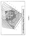
- FIG. 3 is an image of UV discharge current data mapped in a three-dimensional contour, in which the UV discharge current is detected by a UV intensity detection unit;
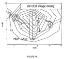
- FIG. 4 a is a combined image of UV discharge current data
- FIG. 4 b is a graph depicting analysis data of the UV discharge current data.
- FIG. 5 is a flowchart of a method of measuring partial discharge using a UV sensor array according to an embodiment of the present invention.
- the apparatus includes a UV sensor array 10 which is positioned at a location separated a predetermined distance from an analyzing target of a power facility, such as an insulator, and includes a plurality of sensors for detecting UV rays emitted from the target; an image measurement unit 20 which measures the distance between the sensor array and the target and supplies an actual image of the target; a UV intensity detection unit 30 which measures intensity of discharge current converted from the UV rays detected by the sensor array; and a UV location detection unit 40 which analyzes and outputs a UV emitting location obtained by matching the discharge current intensity measured by the UV intensity detection unit 30 to combined data of the actual image of the target supplied from the image measurement unit 20 and sensor locations of the sensor array 10 .
- a UV sensor array 10 which is positioned at a location separated a predetermined distance from an analyzing target of a power facility, such as an insulator, and includes a plurality of sensors for detecting UV rays emitted from the target
- an image measurement unit 20 which measures the distance between the sensor array and the
- the UV sensor array 10 may be provided as a detection kit which includes plural sensors combined in a predetermined arrangement on a plane.
- each of the sensors 11 has a predetermined detection region.
- FIG. 2 a is a schematic diagram of a sensor constituting the sensor array according to an embodiment of the present invention.
- the UV sensor 11 includes cathode and anode electrodes 12 and 14 which detect and convert UV rays into discharge current, a guide mirror 16 which guides the UV rays to the electrodes 12 and 14 , and an amplifier 18 which amplifies the converted discharge current.
- the senor may have detection sensitivity for detecting ultraviolet light in the range of 185 ⁇ 260 nm.
- FIG. 2 b is a view illustrating a detection region of the sensors constituting the sensor array
- FIG. 2 c is a view illustrating an area of the detection region of the sensor array according to a measuring distance
- FIG. 2 d is a CCD image of sensor locations in the sensor array.
- each of the sensors arranged in the sensor array 10 detects UV rays within a predetermined detection range on a screen or in the detection region.
- each sensor 11 will become an important factor in determining precision and an analyzing range of the apparatus.
- FIG. 2 c illustrates detection areas depending on a distance of 2 ⁇ 5 m by the sensor array that has a width to length ratio of 1:0.75 and includes 20 sensors.
- the image measurement unit 20 measures the distance between the UV sensor array 10 and the target, and supplies an actual image of the target.
- sensor locations of the sensor array are combined with the actual image of the target of the power facility, which emits UV rays.
- the UV intensity detection unit 30 measures intensity of discharge current obtained by amplifying and converting the UV rays, which have been detected by the sensors of the UV sensor array 10 .
- FIG. 3 is an image of UV discharge current data mapped in a three-dimensional contour, in which the UV discharge current is detected by the UV intensity detection unit 30 .
- arrows indicate the respective sensors constituting the sensor array 10 .
- a particular arrow indicates the highest detection value, which is obtained by a sensor corresponding to the particular arrow.
- the UV location detection unit 40 analyzes locations of the sensors of the sensor array 10 which detect the discharge current, and outputs a UV emitting location based on combined data of the actual image of the target and the sensor locations in the sensor array 10 , as shown in FIG. 2 d.
- FIG. 4 a is a combined image of UV discharge current data
- FIG. 4 b is a graph depicting analysis data of the UV discharge current data.
- a UV emitting location on the target can be verified by matching data of UV discharge current intensity measured by the UV intensity detection unit 30 to combined data of the actual image of the target supplied from the image measurement unit 20 and the sensor locations of the sensor array 10 .
- the apparatus may further include an analysis data output unit 50 that outputs analysis data obtained by combining data of the discharge current intensity measured by the UV intensity detection unit with data of the UV emitting location measured by the UV location detection unit.
- FIG. 4 b shows an example of analysis data, which is obtained by analyzing the intensity and emitting location of discharge current obtained upon detection of UV rays.
- FIG. 5 is a flowchart of a method of measuring partial discharge using a UV sensor array according to an embodiment of the present invention.
- UV-rays emitted from an analyzing target of a power facility are detected by a sensor array, which is separated a predetermined distance from the target and includes a plurality of sensors, in S 10 .
- the UV sensor array 10 is a detection kit which includes plural sensors combined in a predetermined arrangement on a plane.
- each of the sensors has a circumferential detection region, as shown in FIG. 2 b , and can detect discharge UV rays in the corresponding detection region.
- the distance between the UV sensor array 10 and the target is measured and an actual image of the target is supplied by an image measurement unit 20 in S 20 .
- the actual image of the target, and the distance between the NV sensor array 10 and the target are provided as UV detection results of the sensors to obtain an image for detecting a UV emitting location on the target.
- intensity of discharge current obtained by converting the UV rays detected by the sensor array is measured by a UV intensity detection unit 30 in S 30 .
- the NV rays detected by the UV sensors are converted into discharge current, which in turn is amplified to measure an amount of discharge current proportional to intensity of the emitted UV rays and is stored as discharge current data.
- a UV emitting location on the target is output by matching data of the UV discharge current measured by the UV intensity detection unit 30 to combined data of the actual image of the target supplied from the image measurement unit 20 and sensor locations of the sensor array 10 in S 40 .
- the UV location detection unit 40 analyzes locations of the sensors of the sensor array 10 which detect the discharge current, and outputs the UV emitting location on the target of the power facility based on the combined data of the actual image of the target and the sensor locations in the sensor array 10 , as shown in FIG. 2 d.
- the UV intensity detection unit 30 quantifies the intensity of UV rays caused by partial discharge into the discharge current intensity and stores the discharge current intensity data, it is possible to measure the intensity of UV rays with relation to the partial discharge based on the data.
- the apparatus for measuring partial discharge using a UV sensor array can employ discharge current to detect intensity and emitting locations of UV rays, which are caused by insulation deterioration of power facilities or discharge in air, and can provide analysis data of discharge quantity.
- the apparatus according to the present invention enables easy substitution of components through modification of the sensor array, and can be applied to a portable or on-line monitoring system, which can be used by an expert or an amateur in practice.
Landscapes
- Physics & Mathematics (AREA)
- General Physics & Mathematics (AREA)
- Spectroscopy & Molecular Physics (AREA)
- Engineering & Computer Science (AREA)
- Human Computer Interaction (AREA)
- Testing Relating To Insulation (AREA)
- Photometry And Measurement Of Optical Pulse Characteristics (AREA)
Abstract
Description
Claims (4)
Applications Claiming Priority (2)
| Application Number | Priority Date | Filing Date | Title |
|---|---|---|---|
| KR10-2008-0136501 | 2008-12-30 | ||
| KR1020080136501A KR101028884B1 (en) | 2008-12-30 | 2008-12-30 | Apparatus and method for measuring partial discharge amount using UV sensor array |
Publications (2)
| Publication Number | Publication Date |
|---|---|
| US20100163743A1 US20100163743A1 (en) | 2010-07-01 |
| US8076648B2 true US8076648B2 (en) | 2011-12-13 |
Family
ID=42283686
Family Applications (1)
| Application Number | Title | Priority Date | Filing Date |
|---|---|---|---|
| US12/472,923 Expired - Fee Related US8076648B2 (en) | 2008-12-30 | 2009-05-27 | Partial discharge measuring apparatus using UV sensor array and method thereof |
Country Status (2)
| Country | Link |
|---|---|
| US (1) | US8076648B2 (en) |
| KR (1) | KR101028884B1 (en) |
Cited By (3)
| Publication number | Priority date | Publication date | Assignee | Title |
|---|---|---|---|---|
| RU2661976C2 (en) * | 2013-03-13 | 2018-07-23 | Ссир | Apparatus, methods and systems for measuring and detecting electrical discharge |
| RU196867U1 (en) * | 2020-01-09 | 2020-03-18 | Акционерное общество "Научно-производственное объединение "Государственный институт прикладной оптики" (АО "НПО ГИПО") | DEVICE FOR DETECTION AND MEASUREMENT OF ELECTRIC DISCHARGE OF HIGH VOLTAGE EQUIPMENT |
| RU2737516C1 (en) * | 2020-01-09 | 2020-12-01 | Акционерное общество "Научно-производственное объединение "Государственный институт прикладной оптики" (АО "НПО ГИПО") | Device for detection and measurement of electric discharge of high-voltage equipment |
Families Citing this family (15)
| Publication number | Priority date | Publication date | Assignee | Title |
|---|---|---|---|---|
| KR101102547B1 (en) | 2010-11-02 | 2012-01-03 | (주)케이제이다이나텍 | Degradation sensor for electrical insulation equipment and device state analysis device using the sensor |
| EP2466324B1 (en) | 2010-12-15 | 2013-07-24 | ABB Technology AG | Combined measuring and detection system |
| CN102221653A (en) * | 2011-03-30 | 2011-10-19 | 四川省电力公司自贡电业局 | Electric power equipment discharge detector based on ultraviolet light power method |
| JP5854468B2 (en) * | 2012-01-25 | 2016-02-09 | 国立大学法人九州工業大学 | Non-contact discharge evaluation method and apparatus |
| CN103217635B (en) * | 2013-05-03 | 2016-03-23 | 上海理工大学 | A kind of shelf depreciation uv detection devices |
| CN104237746A (en) * | 2013-06-13 | 2014-12-24 | 成都昊地科技有限责任公司 | Partial discharge detector used for electrical equipment |
| KR101332715B1 (en) * | 2013-08-19 | 2013-11-26 | 한국 전기안전공사 | Method for diagnosising power facility using uv camera |
| JP6158134B2 (en) * | 2014-04-24 | 2017-07-05 | 株式会社東芝 | Discharge position specifying device, discharge position measuring device, and discharge position specifying method |
| KR101696619B1 (en) | 2014-08-20 | 2017-01-18 | 한국철도기술연구원 | Apparatus for preventing background discharge of uv tron sensor |
| CN105093078A (en) * | 2015-08-25 | 2015-11-25 | 上海理工大学 | Generator stator winding partial discharge ultraviolet detection device |
| CN105699866B (en) * | 2016-02-22 | 2018-08-28 | 株洲壹星科技股份有限公司 | The method for detecting rail traffic insulating element using UV corona technology |
| CN106054032B (en) * | 2016-03-08 | 2020-03-03 | 华北电力大学(保定) | A non-contact measurement method for the peak value of the creeping discharge pulse of high-voltage insulators |
| CN106093738A (en) * | 2016-08-26 | 2016-11-09 | 张振堂 | A kind of middle-low voltage switch cabinet online detector for partial discharge |
| CN110275098B (en) * | 2019-06-28 | 2021-07-09 | 杭州赫太克科技有限公司 | Ultraviolet imager |
| CN112285497B (en) * | 2020-10-13 | 2024-05-10 | 国网江苏省电力有限公司无锡供电分公司 | Partial discharge detection device of gas insulation equipment and gas insulation equipment |
Citations (1)
| Publication number | Priority date | Publication date | Assignee | Title |
|---|---|---|---|---|
| US6700496B2 (en) * | 2001-01-06 | 2004-03-02 | Xcounter Ab | Flame and spark detector, automatic fire alarm and methods related thereto |
Family Cites Families (2)
| Publication number | Priority date | Publication date | Assignee | Title |
|---|---|---|---|---|
| JPH08122399A (en) * | 1994-10-28 | 1996-05-17 | Kokusai Gijutsu Kaihatsu Kk | Discharge monitoring system |
| JP2007292489A (en) * | 2006-04-21 | 2007-11-08 | Toshiba Corp | Insulation abnormality diagnosis system for electrical equipment |
-
2008
- 2008-12-30 KR KR1020080136501A patent/KR101028884B1/en not_active Expired - Fee Related
-
2009
- 2009-05-27 US US12/472,923 patent/US8076648B2/en not_active Expired - Fee Related
Patent Citations (1)
| Publication number | Priority date | Publication date | Assignee | Title |
|---|---|---|---|---|
| US6700496B2 (en) * | 2001-01-06 | 2004-03-02 | Xcounter Ab | Flame and spark detector, automatic fire alarm and methods related thereto |
Non-Patent Citations (2)
| Title |
|---|
| Moore et al., Remote Sensing of Voltage Using Optical Assessment of Corona, 2000, IEEE, pp. 1159-1164. * |
| Zang et al., Research on Mechanism and Ultraviolet Imaging of Corona Discharge of Electric Device Faults, Jul. 18, 2008, IEEE, pp. 690-693. * |
Cited By (3)
| Publication number | Priority date | Publication date | Assignee | Title |
|---|---|---|---|---|
| RU2661976C2 (en) * | 2013-03-13 | 2018-07-23 | Ссир | Apparatus, methods and systems for measuring and detecting electrical discharge |
| RU196867U1 (en) * | 2020-01-09 | 2020-03-18 | Акционерное общество "Научно-производственное объединение "Государственный институт прикладной оптики" (АО "НПО ГИПО") | DEVICE FOR DETECTION AND MEASUREMENT OF ELECTRIC DISCHARGE OF HIGH VOLTAGE EQUIPMENT |
| RU2737516C1 (en) * | 2020-01-09 | 2020-12-01 | Акционерное общество "Научно-производственное объединение "Государственный институт прикладной оптики" (АО "НПО ГИПО") | Device for detection and measurement of electric discharge of high-voltage equipment |
Also Published As
| Publication number | Publication date |
|---|---|
| KR20100078282A (en) | 2010-07-08 |
| US20100163743A1 (en) | 2010-07-01 |
| KR101028884B1 (en) | 2011-04-12 |
Similar Documents
| Publication | Publication Date | Title |
|---|---|---|
| US8076648B2 (en) | Partial discharge measuring apparatus using UV sensor array and method thereof | |
| US8918298B2 (en) | Solar cell evaluation device and solar cell evaluation method | |
| US20210366091A1 (en) | Mobile ingredient analysis system, and method for true-to-sample measurement and user guidance by means of same | |
| US20150060643A1 (en) | Methods and Systems for In Situ Calibration of Imaging in Biological Analysis | |
| TWI546534B (en) | Inspecting device, computer device and method for inter-cell cross-line inspection of database driving | |
| CN116430271B (en) | An online testing method, smart terminal, and storage medium for LED flexible light strips. | |
| KR20120008294A (en) | Device for Diagnosing Radiation Degradation Characteristics of Electronic Equipment Using CMOS Semiconductor Devices | |
| US20080094469A1 (en) | Circuitry testing method and circuitry testing device | |
| KR20200073442A (en) | Method for Checking Sensor of Gas Detector | |
| US20130182252A1 (en) | Scattered light measuring method | |
| US7244940B2 (en) | Gas sensor arrangement and measuring method for improving long-term stability | |
| US11940378B2 (en) | Spectrometer system and method for testing of same | |
| CN117991060A (en) | Partial discharge detection method, device, electronic equipment and storage medium | |
| CN116448282B (en) | Fault self-diagnosis method of fluorescent optical fiber temperature measurement sensor | |
| KR200451226Y1 (en) | Portable discharge ultraviolet light analyzer | |
| JP5334183B2 (en) | Inspection device and inspection method | |
| US12055498B2 (en) | Data processing method and system for detection of deterioration of semiconductor process kits | |
| KR101094158B1 (en) | Abnormality test circuit and method of gas flow proportional counter type radiation detector | |
| JP7234040B2 (en) | Oxygen concentration measurement system and oxygen concentration measurement method | |
| CN111157499A (en) | Method for calibrating fluorescence detection instrument | |
| WO2015052822A1 (en) | Testing apparatus and testing method | |
| EP4624901A1 (en) | Cable joint gas measuring device | |
| CN114527112B (en) | Diagnostic test method for spectrometer | |
| CN119064586B (en) | Endocrinology blood sugar data monitoring method and system | |
| US20240192144A1 (en) | Substrate inspecting apparatus and operating method thereof |
Legal Events
| Date | Code | Title | Description |
|---|---|---|---|
| AS | Assignment |
Owner name: KOREA ELECTRIC SAFETY CORP.,KOREA, REPUBLIC OF Free format text: ASSIGNMENT OF ASSIGNORS INTEREST;ASSIGNORS:SHONG, KIL MOK;KIM, YOUNG SEOK;REEL/FRAME:022740/0325 Effective date: 20090522 Owner name: KOREA ELECTRIC SAFETY CORP., KOREA, REPUBLIC OF Free format text: ASSIGNMENT OF ASSIGNORS INTEREST;ASSIGNORS:SHONG, KIL MOK;KIM, YOUNG SEOK;REEL/FRAME:022740/0325 Effective date: 20090522 |
|
| ZAAA | Notice of allowance and fees due |
Free format text: ORIGINAL CODE: NOA |
|
| ZAAB | Notice of allowance mailed |
Free format text: ORIGINAL CODE: MN/=. |
|
| STCF | Information on status: patent grant |
Free format text: PATENTED CASE |
|
| FPAY | Fee payment |
Year of fee payment: 4 |
|
| MAFP | Maintenance fee payment |
Free format text: PAYMENT OF MAINTENANCE FEE, 8TH YEAR, LARGE ENTITY (ORIGINAL EVENT CODE: M1552); ENTITY STATUS OF PATENT OWNER: LARGE ENTITY Year of fee payment: 8 |
|
| FEPP | Fee payment procedure |
Free format text: MAINTENANCE FEE REMINDER MAILED (ORIGINAL EVENT CODE: REM.); ENTITY STATUS OF PATENT OWNER: LARGE ENTITY |
|
| LAPS | Lapse for failure to pay maintenance fees |
Free format text: PATENT EXPIRED FOR FAILURE TO PAY MAINTENANCE FEES (ORIGINAL EVENT CODE: EXP.); ENTITY STATUS OF PATENT OWNER: LARGE ENTITY |
|
| STCH | Information on status: patent discontinuation |
Free format text: PATENT EXPIRED DUE TO NONPAYMENT OF MAINTENANCE FEES UNDER 37 CFR 1.362 |
|
| FP | Lapsed due to failure to pay maintenance fee |
Effective date: 20231213 |