US8074716B2 - Tension-activated fluid bypass device and associated method - Google Patents
Tension-activated fluid bypass device and associated method Download PDFInfo
- Publication number
- US8074716B2 US8074716B2 US12/503,931 US50393109A US8074716B2 US 8074716 B2 US8074716 B2 US 8074716B2 US 50393109 A US50393109 A US 50393109A US 8074716 B2 US8074716 B2 US 8074716B2
- Authority
- US
- United States
- Prior art keywords
- tool
- fluid
- latching
- condition
- bypass
- Prior art date
- Legal status (The legal status is an assumption and is not a legal conclusion. Google has not performed a legal analysis and makes no representation as to the accuracy of the status listed.)
- Expired - Fee Related, expires
Links
- 239000012530 fluid Substances 0.000 title claims abstract description 93
- 238000000034 method Methods 0.000 title claims description 6
- 230000006835 compression Effects 0.000 description 4
- 238000007906 compression Methods 0.000 description 4
- 238000005086 pumping Methods 0.000 description 3
- 238000004891 communication Methods 0.000 description 2
- 241000251468 Actinopterygii Species 0.000 description 1
- 239000004215 Carbon black (E152) Substances 0.000 description 1
- 230000004323 axial length Effects 0.000 description 1
- 230000000903 blocking effect Effects 0.000 description 1
- 229930195733 hydrocarbon Natural products 0.000 description 1
- 150000002430 hydrocarbons Chemical class 0.000 description 1
- 230000003116 impacting effect Effects 0.000 description 1
- 238000004519 manufacturing process Methods 0.000 description 1
- 238000012986 modification Methods 0.000 description 1
- 230000004048 modification Effects 0.000 description 1
- 230000000717 retained effect Effects 0.000 description 1
Images


Classifications
-
- E—FIXED CONSTRUCTIONS
- E21—EARTH OR ROCK DRILLING; MINING
- E21B—EARTH OR ROCK DRILLING; OBTAINING OIL, GAS, WATER, SOLUBLE OR MELTABLE MATERIALS OR A SLURRY OF MINERALS FROM WELLS
- E21B21/00—Methods or apparatus for flushing boreholes, e.g. by use of exhaust air from motor
- E21B21/10—Valve arrangements in drilling-fluid circulation systems
- E21B21/103—Down-hole by-pass valve arrangements, i.e. between the inside of the drill string and the annulus
Definitions
- the present invention generally relates to fluid bypass devices used with fishing arrangements within a wellbore and the like.
- Fishing arrangements are used to try to remove stuck tools or devices from the interior of a wellbore.
- the stuck tool typically has an upper end fishing neck that can be engaged by a latching tool on a running string.
- Two common latching tools are known as a spear and an overshot tool.
- the latching tool is actuated using hydraulic pressure to be latched and unlatched from the fishing neck. In such a case, unobstructed fluid flow from the surface is needed to operate the latching tool, since the latching tool is unlatched from the fishing neck by pumping of a predetermined rate of fluid through the latching tool.
- the inventors have recognized that fluid flow through the running string to operate other tools within the running string can inadvertently cause the latching tool to be released from the fishing neck of the stuck tool, which is undesirable.
- the present invention provides a fluid bypass tool that can be incorporated into a fishing arrangement between a fluid-operated latching tool and a fluid-operated jarring tool.
- the latching tool uses fluid pumped from the surface to become latched to and unlatched from a stuck tool in the wellbore.
- the bypass tool permits fluid flow to the latching tool to be interrupted so that the jarring tool may be operated without risk of inadvertently causing the latching tool to unlatch from the stuck tool.
- fluid flow to the latching tool is interrupted by the bypass tool, fluid flow from the surface may be used to operate the jarring tool.
- An exemplary bypass tool which includes a tool body that is made up of first and second body sections that are axially moveable with respect to each other.
- the bypass tool sections are moveable between a first, run-in condition or position, wherein fluid can be flowed from one axial end of the tool to the other axial end, and a second, actuated condition or position, wherein fluid flow into the first axial end of the tool is diverted radially outwardly through the body of the tool.
- lateral fluid flow ports are unblocked which divert fluid flow into the surrounding wellbore, thereby bypassing the latching tool.
- the body sections are spring-biased toward the first, run-in condition but activated by tension on the running string to move to the activated condition.
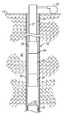
- FIG. 1 is a side, cross-sectional view of an exemplary wellbore containing a running string with a latching tool, an impacting tool and a bypass tool constructed in accordance with the present invention.
- FIG. 2 is a side, cross-sectional view of an exemplary bypass tool, constructed in accordance with the present invention, in a run-in condition.
- FIG. 3 is a side, cross-sectional view of the bypass tool shown in FIG. 2 , now in an actuated condition.
- FIG. 4 is side, cross-sectional view of a bottom sub used within the bypass tool shown in FIGS. 2 and 3 .
- FIG. 5 is an isometric view of the bottom sub shown in FIG. 4 .
- FIG. 1 illustrates an exemplary subterranean hydrocarbon production wellbore 10 that has drilled through the earth 12 from the surface 14 and lined with casing 16 .
- a stuck tool 18 is shown disposed within the casing 16 , and presents a fishing neck 20 by which the tool 18 can be engaged by a fishing arrangement.
- a fluid pump 22 At the surface 14 of the wellbore 10 is a fluid pump 22 that is operable to flow fluid downwardly through a fishing arrangement.
- a fishing arrangement is disposed within the wellbore 10 above the stuck tool 18 .
- the fishing arrangement 24 includes a running string 26 that extends downwardly from the surface 14 of the wellbore 10 .
- the running string 26 is preferably formed of sections of interconnected tubing of a type known in the art. However, it is also contemplated that coiled tubing can be used.
- a central fluid flowbore 27 is defined within the running string 26 .
- a fluid-operated impact-type jarring tool 28 is affixed to the lower end of the running string 26 .
- One suitable fluid-operated jarring tool which is suitable for use as the jarring tool 28 is the MG3 jarring tool which is available commercially from Baker Hughes Incorporated of Houston, Tex.
- jarring tools are commercially available as well from other manufacturers/vendors and which are typically referred to as “impact hammers” or “impact jars.”
- the term “fluid-operated” when used with respect to the jarring tool 28 is intended to mean that the jarring tool 28 is actuated by a flow of fluid through the tool 28 from the surface-based fluid pump 22 .
- a fluid bypass tool 30 is operably connected with the lower end of the jarring tool 28 .
- FIG. 1 shows the fluid bypass tool 30 to be directly affixed to the jarring tool 28
- the two components may be operably connected to each other via one or more intermediate tools or tubing string sections.
- An overshot latching tool 32 is operably connected with the lower end of the fluid bypass tool 30 . Again, although these two components are shown directly interconnected, there may be intermediate components.
- the overshot latching tool 32 is designed to engage the fishing neck 20 of the stuck tool 18 in order to attempt to retrieve it from the wellbore 10 .
- the latching tool 32 is also fluid-operated in that the latching and/or unlatching of the tool 32 from the fishing neck 20 requires or uses, at least in part a flow of fluid downwardly through the fishing arrangement 24 from the surface-based fluid pump 22 through the latching tool 32 .
- these tools have a flow release feature that allows release of the tool 32 from the stuck object 18 by pumping a predetermined flow rate which will move a collet or slip into a release position. If the fish, or stuck object, 18 is unable to pull free, one can release the latching tool 32 from the stuck object 18 by setting weight down and pumping fluid through the latching tool 32 to release it from the stuck object 18 and thereafter returning the released fishing arrangement 24 to the surface 14 .
- FIGS. 2-3 illustrate an exemplary fluid bypass tool 30 constructed in accordance with the present invention in greater detail.
- the bypass tool 30 includes a tool body 50 having an upper axial end 52 and a lower axial end 54 .
- a central flowbore 56 is defined along the axial length of the tool body 50 .
- the upper end 52 of the tool body 50 is provided by an upper sub 58 .
- the upper sub 58 provides a box-type threaded portion 60 to permit the upper sub 58 to be affixed to the jarring tool 28 .
- the upper sub 58 is threadedly affixed to a mandrel 62 .
- the mandrel 62 includes a reduced diameter shaft 64 and an enlarged-diameter chamber housing 66 .
- a flowbore portion 68 is defined generally within the shaft 64 .
- Inner lateral fluid flow ports 70 are disposed through the shaft 64 to permit fluid communication between the flowbore portion 68 and the area radially surrounding the shaft 64 .
- the chamber housing 66 of the mandrel 62 defines an enlarged-diameter fluid chamber 72 which is in fluid communication with the flowbore portion 68 .
- the fluid chamber 72 adjoins a reduced diameter neck 74 .
- Annular fluid seals 76 and 78 are disposed within the neck 74 .
- a retainer 80 radially surrounds the shaft 64 of the mandrel 62 .
- the retainer has a reduced diameter inner surface 82 and an enlarged diameter inner surface 84 .
- a spring chamber 86 is defined therebetween.
- Compression spring 88 is retained within the spring chamber 86 .
- the upper end of the compression spring 88 abuts a downward-facing shoulder 90 on the retainer 80 while the lower end of the compression spring 88 abuts an upward-facing shoulder 92 on the chamber housing 66 .
- a set of lateral fluid equalization ports 94 are disposed through the retainer 80 to permit surrounding well fluids to flow into and out of the spring chamber 86 .
- a tubular sleeve 96 is affixed by a first threaded connection 98 to the retainer 80 .
- the sleeve 96 is also affixed by a second threaded connection 100 to a bottom sub 102 .
- the bottom sub 102 is shown in greater detail in FIGS. 4 and 5 .
- the bottom sub 102 features a sub body 104 which defines a central bore 106 .
- the lower end of the sub body 104 presents a threaded pin-type connection 108 which permits the fluid bypass tool 30 to be interconnected to the latching tool 32 .
- the sub body 104 also includes an enlarged central portion 110 with an external threaded portion 112 by which the bottom sub 102 can be affixed to the sleeve 96 .
- a fluid deflector portion 114 extends axially from the central portion 110 and includes a cylindrical outer radial surface 116 and a distal conical fluid deflector surface 118 .
- One of more angled fluid passages 120 are disposed through the fluid deflector portion 114 and permit fluid to flow into the central bore 106 .
- FIG. 2 depicts the bypass tool 30 in an initial run in condition wherein the compression spring 88 is substantially uncompressed.
- the spring 88 biases the retainer 80 upwardly with respect to the internal mandrel 62 until the retainer 80 is in contact with the upper sub 58 .
- the cylindrical outer radial surface 116 of the fluid deflector portion 114 of bottom sub 102 is located within the neck 74 of the mandrel 62 .
- fluid flow through the lateral fluid flow ports 70 of the mandrel shaft 64 is blocked by the retainer 80 .
- Annular fluid seals 122 are located on each axial side of the ports 70 to isolate them.
- Fluid flowing downwardly through the central flowbore 56 from the direction of the upper end 52 will enter the fluid chamber 72 and be transmitted through the angled fluid passages 120 to the central bore 106 of the bottom sub 102 . Therefore, fluid can flow downwardly through the bypass tool 30 to reach and operate the overshot latching tool 32 .
- the fishing arrangement 24 is run into the wellbore 10 and lowered until the overshot latching tool 32 engages the fishing neck 20 of the stuck tool 18 . Once this is done, it is desired to operate the jarring tool 28 to try to remove the stuck tool 18 .
- the inventors have recognized that it is also desirable at this time to cut off fluid flow to the latching tool 32 in order to prevent it from being inadvertently unlatched from the fishing neck 20 by variations in fluid pressure in the flowbore 27 during operation of the jarring tool 28 .
- An overpull on the running string 26 is used to move the bypass tool 30 from the run in configuration shown in FIG. 2 to the actuated configuration shown in FIG. 3 .
- the force of the overpull must be sufficient to overcome the biasing force of the spring 88 and compress it.
- the upper sub 58 and affixed mandrel 62 move axially upwardly with respect to the bottom sub 102 , sleeve 96 and retainer 80 .
- the spring 88 is compressed.
- the neck 74 of the mandrel 62 covers the angled fluid passages 120 of the bottom sub 102 , thereby blocking fluid flow through them and into the central bore 106 .
- Fluid seals 76 , 78 help to isolate the passages 120 .
- the retainer 80 is moved downwardly upon the mandrel shaft 64 so that the lateral flow ports 70 are unblocked.
- fluid flowing through the central flowbore 56 will be expelled into the wellbore 10 .
- fluid flowing through the jarring tool 28 and into the bypass tool 30 will still operate the jarring tool 28 .
- first tool section collectively form a first tool section
- bottom sub 102 , sleeve 96 and retainer 80 collectively form a second tool section.
- the first and second tool sections are axially moveable with respect to each other between the first, run-in condition and the second, actuated condition.
- the invention also provides a method for selectively diverting fluid flow from the fluid-operated latching tool 32 while permitting the fluid-operated jarring tool 28 to be operated by fluid flowed through the running string 26 .
- the invention provides a method and system for removing a stuck tool or object 18 from within a wellbore 10 .
- a fishing arrangement 24 is disposed into the wellbore 10 having a fluid-operated jarring tool 28 , a fluid-operated latching tool 32 and a fluid bypass tool 30 disposed between the jarring tool 28 and the latching tool 32 .
- the latching tool 32 is latched to the stuck tool or object 18 using fluid flow through the fishing arrangement 24 to accomplish the latching.
- the bypass tool 30 is actuated to divert the fluid flow from entering the latching tool 32 .
- Fluid flow through the fishing arrangement 24 then actuates the jarring tool 28 to remove the stuck tool or object 18 .
Landscapes
- Engineering & Computer Science (AREA)
- Life Sciences & Earth Sciences (AREA)
- Geology (AREA)
- Mining & Mineral Resources (AREA)
- Mechanical Engineering (AREA)
- Physics & Mathematics (AREA)
- Environmental & Geological Engineering (AREA)
- Fluid Mechanics (AREA)
- General Life Sciences & Earth Sciences (AREA)
- Geochemistry & Mineralogy (AREA)
Abstract
Description
Claims (16)
Priority Applications (4)
| Application Number | Priority Date | Filing Date | Title |
|---|---|---|---|
| US12/503,931 US8074716B2 (en) | 2009-07-16 | 2009-07-16 | Tension-activated fluid bypass device and associated method |
| GB1118101.3A GB2484015B (en) | 2009-07-16 | 2010-09-16 | Tension-activated fluid bypass device |
| AU2010273969A AU2010273969B2 (en) | 2009-07-16 | 2010-09-16 | Tension-activated fluid bypass device |
| PCT/US2010/049118 WO2011009145A2 (en) | 2009-07-16 | 2010-09-16 | Tension-activated fluid bypass device |
Applications Claiming Priority (1)
| Application Number | Priority Date | Filing Date | Title |
|---|---|---|---|
| US12/503,931 US8074716B2 (en) | 2009-07-16 | 2009-07-16 | Tension-activated fluid bypass device and associated method |
Publications (2)
| Publication Number | Publication Date |
|---|---|
| US20110011588A1 US20110011588A1 (en) | 2011-01-20 |
| US8074716B2 true US8074716B2 (en) | 2011-12-13 |
Family
ID=43450273
Family Applications (1)
| Application Number | Title | Priority Date | Filing Date |
|---|---|---|---|
| US12/503,931 Expired - Fee Related US8074716B2 (en) | 2009-07-16 | 2009-07-16 | Tension-activated fluid bypass device and associated method |
Country Status (4)
| Country | Link |
|---|---|
| US (1) | US8074716B2 (en) |
| AU (1) | AU2010273969B2 (en) |
| GB (1) | GB2484015B (en) |
| WO (1) | WO2011009145A2 (en) |
Cited By (3)
| Publication number | Priority date | Publication date | Assignee | Title |
|---|---|---|---|---|
| US9551199B2 (en) | 2014-10-09 | 2017-01-24 | Impact Selector International, Llc | Hydraulic impact apparatus and methods |
| US9631445B2 (en) | 2013-06-26 | 2017-04-25 | Impact Selector International, Llc | Downhole-adjusting impact apparatus and methods |
| US9644441B2 (en) | 2014-10-09 | 2017-05-09 | Impact Selector International, Llc | Hydraulic impact apparatus and methods |
Families Citing this family (5)
| Publication number | Priority date | Publication date | Assignee | Title |
|---|---|---|---|---|
| SG178378A1 (en) * | 2009-08-13 | 2012-04-27 | Wellbore Energy Solutions Llc | Repeatable, compression set downhole bypass valve |
| US8550176B2 (en) | 2010-02-09 | 2013-10-08 | Halliburton Energy Services, Inc. | Wellbore bypass tool and related methods of use |
| EP2418857A1 (en) * | 2010-08-12 | 2012-02-15 | Thomson Licensing | Stereoscopic menu control |
| CN105003222A (en) * | 2015-06-25 | 2015-10-28 | 山西宏厦第一建设有限责任公司 | Method of fishing jammed pipe of 1000m directional drilling machine |
| US11913323B2 (en) | 2022-02-07 | 2024-02-27 | Daniel J. Snyder | Desander assembly for plunger lift system |
Citations (6)
| Publication number | Priority date | Publication date | Assignee | Title |
|---|---|---|---|---|
| US2732901A (en) * | 1956-01-31 | Davis | ||
| US3735827A (en) * | 1972-03-15 | 1973-05-29 | Baker Oil Tools Inc | Down-hole adjustable hydraulic fishing jar |
| US3765487A (en) * | 1972-06-16 | 1973-10-16 | Shell Oil Co | Apparatus and method for releasing differentially stuck pipe |
| US3800876A (en) * | 1971-04-26 | 1974-04-02 | Tenneco Oil Co | Method for dislodging a pipe string |
| US5170845A (en) * | 1991-05-13 | 1992-12-15 | Otis Engineering Corp. | Subsurface safety valves and method and apparatus for their operation |
| US7281575B2 (en) * | 2003-10-30 | 2007-10-16 | Mcelroy Fay | Field adjustable impact jar |
Family Cites Families (3)
| Publication number | Priority date | Publication date | Assignee | Title |
|---|---|---|---|---|
| US4648445A (en) * | 1985-12-13 | 1987-03-10 | Halliburton Company | Retrieving mechanism |
| US6338387B1 (en) * | 1998-11-30 | 2002-01-15 | Downhole Research, Llc | Downward energized motion jars |
| US6502638B1 (en) * | 1999-10-18 | 2003-01-07 | Baker Hughes Incorporated | Method for improving performance of fishing and drilling jars in deviated and extended reach well bores |
-
2009
- 2009-07-16 US US12/503,931 patent/US8074716B2/en not_active Expired - Fee Related
-
2010
- 2010-09-16 WO PCT/US2010/049118 patent/WO2011009145A2/en not_active Ceased
- 2010-09-16 GB GB1118101.3A patent/GB2484015B/en not_active Expired - Fee Related
- 2010-09-16 AU AU2010273969A patent/AU2010273969B2/en not_active Ceased
Patent Citations (6)
| Publication number | Priority date | Publication date | Assignee | Title |
|---|---|---|---|---|
| US2732901A (en) * | 1956-01-31 | Davis | ||
| US3800876A (en) * | 1971-04-26 | 1974-04-02 | Tenneco Oil Co | Method for dislodging a pipe string |
| US3735827A (en) * | 1972-03-15 | 1973-05-29 | Baker Oil Tools Inc | Down-hole adjustable hydraulic fishing jar |
| US3765487A (en) * | 1972-06-16 | 1973-10-16 | Shell Oil Co | Apparatus and method for releasing differentially stuck pipe |
| US5170845A (en) * | 1991-05-13 | 1992-12-15 | Otis Engineering Corp. | Subsurface safety valves and method and apparatus for their operation |
| US7281575B2 (en) * | 2003-10-30 | 2007-10-16 | Mcelroy Fay | Field adjustable impact jar |
Cited By (4)
| Publication number | Priority date | Publication date | Assignee | Title |
|---|---|---|---|---|
| US9631445B2 (en) | 2013-06-26 | 2017-04-25 | Impact Selector International, Llc | Downhole-adjusting impact apparatus and methods |
| US10370922B2 (en) | 2013-06-26 | 2019-08-06 | Impact Selector International, Llc | Downhole-Adjusting impact apparatus and methods |
| US9551199B2 (en) | 2014-10-09 | 2017-01-24 | Impact Selector International, Llc | Hydraulic impact apparatus and methods |
| US9644441B2 (en) | 2014-10-09 | 2017-05-09 | Impact Selector International, Llc | Hydraulic impact apparatus and methods |
Also Published As
| Publication number | Publication date |
|---|---|
| AU2010273969B2 (en) | 2014-07-03 |
| GB2484015B (en) | 2013-09-11 |
| GB201118101D0 (en) | 2011-11-30 |
| WO2011009145A3 (en) | 2011-05-12 |
| WO2011009145A2 (en) | 2011-01-20 |
| GB2484015A (en) | 2012-03-28 |
| US20110011588A1 (en) | 2011-01-20 |
| AU2010273969A1 (en) | 2011-11-10 |
Similar Documents
| Publication | Publication Date | Title |
|---|---|---|
| US8074716B2 (en) | Tension-activated fluid bypass device and associated method | |
| US4708208A (en) | Method and apparatus for setting, unsetting, and retrieving a packer from a subterranean well | |
| US4869325A (en) | Method and apparatus for setting, unsetting, and retrieving a packer or bridge plug from a subterranean well | |
| US6695057B2 (en) | Fracturing port collar for wellbore pack-off system, and method for using same | |
| US8881835B2 (en) | Manipulator tool and tool catcher useful with wellbore reverse circulation | |
| US9574417B2 (en) | Wireline hydraulic driven mill bottom hole assemblies and methods of using same | |
| US7051812B2 (en) | Fracturing tool having tubing isolation system and method | |
| US4805699A (en) | Method and apparatus for setting, unsetting, and retrieving a packer or bridge plug from a subterranean well | |
| US10961808B2 (en) | Tension release packer for a bottomhole assembly and methods of use | |
| US20140290939A1 (en) | Exercising a Well Tool | |
| AU751952B2 (en) | Bottom hole assembly with coiled tubing insert | |
| US11643896B2 (en) | Removing obstructions in a wellbore | |
| US5791712A (en) | Spear fishing tool | |
| US5253712A (en) | Rotationally operated back pressure valve | |
| US7347269B2 (en) | Flow tube exercising tool | |
| US20090145605A1 (en) | Staged Actuation Shear Sub for Use Downhole | |
| US4573539A (en) | Hydraulically pulsed indexing system for sleeve-type core barrels | |
| US9822599B2 (en) | Pressure lock for jars | |
| AU3337601A (en) | Zero drill completion and production system | |
| US11174692B2 (en) | Crown plug pulling tool with bailer feature | |
| NO342662B1 (en) | Stretch-activated fluid bypass unit |
Legal Events
| Date | Code | Title | Description |
|---|---|---|---|
| AS | Assignment |
Owner name: BAKER HUGHES INCORPORATED, TEXAS Free format text: ASSIGNMENT OF ASSIGNORS INTEREST;ASSIGNORS:MELDER, JACE E.;CHAMPAGNE, JOHNNY N.;COLEMAN, DAVID W.;REEL/FRAME:023154/0517 Effective date: 20090826 |
|
| ZAAA | Notice of allowance and fees due |
Free format text: ORIGINAL CODE: NOA |
|
| ZAAB | Notice of allowance mailed |
Free format text: ORIGINAL CODE: MN/=. |
|
| STCF | Information on status: patent grant |
Free format text: PATENTED CASE |
|
| FPAY | Fee payment |
Year of fee payment: 4 |
|
| MAFP | Maintenance fee payment |
Free format text: PAYMENT OF MAINTENANCE FEE, 8TH YEAR, LARGE ENTITY (ORIGINAL EVENT CODE: M1552); ENTITY STATUS OF PATENT OWNER: LARGE ENTITY Year of fee payment: 8 |
|
| AS | Assignment |
Owner name: BAKER HUGHES, A GE COMPANY, LLC, TEXAS Free format text: CHANGE OF NAME;ASSIGNOR:BAKER HUGHES INCORPORATED;REEL/FRAME:059485/0502 Effective date: 20170703 |
|
| AS | Assignment |
Owner name: BAKER HUGHES HOLDINGS LLC, TEXAS Free format text: CHANGE OF NAME;ASSIGNOR:BAKER HUGHES, A GE COMPANY, LLC;REEL/FRAME:059596/0405 Effective date: 20200413 |
|
| FEPP | Fee payment procedure |
Free format text: MAINTENANCE FEE REMINDER MAILED (ORIGINAL EVENT CODE: REM.); ENTITY STATUS OF PATENT OWNER: LARGE ENTITY |
|
| LAPS | Lapse for failure to pay maintenance fees |
Free format text: PATENT EXPIRED FOR FAILURE TO PAY MAINTENANCE FEES (ORIGINAL EVENT CODE: EXP.); ENTITY STATUS OF PATENT OWNER: LARGE ENTITY |
|
| STCH | Information on status: patent discontinuation |
Free format text: PATENT EXPIRED DUE TO NONPAYMENT OF MAINTENANCE FEES UNDER 37 CFR 1.362 |
|
| FP | Lapsed due to failure to pay maintenance fee |
Effective date: 20231213 |