US8074344B2 - Method of manufacturing rotor holder - Google Patents
Method of manufacturing rotor holder Download PDFInfo
- Publication number
- US8074344B2 US8074344B2 US12/145,528 US14552808A US8074344B2 US 8074344 B2 US8074344 B2 US 8074344B2 US 14552808 A US14552808 A US 14552808A US 8074344 B2 US8074344 B2 US 8074344B2
- Authority
- US
- United States
- Prior art keywords
- rotor holder
- side wall
- hole
- wall portion
- top plate
- Prior art date
- Legal status (The legal status is an assumption and is not a legal conclusion. Google has not performed a legal analysis and makes no representation as to the accuracy of the status listed.)
- Expired - Fee Related, expires
Links
- 238000004519 manufacturing process Methods 0.000 title claims abstract description 45
- 239000002184 metal Substances 0.000 claims abstract description 49
- ZZUFCTLCJUWOSV-UHFFFAOYSA-N furosemide Chemical compound C1=C(Cl)C(S(=O)(=O)N)=CC(C(O)=O)=C1NCC1=CC=CO1 ZZUFCTLCJUWOSV-UHFFFAOYSA-N 0.000 claims abstract description 18
- 230000000750 progressive effect Effects 0.000 claims description 22
- 238000000034 method Methods 0.000 claims description 12
- 238000004080 punching Methods 0.000 claims 4
- 238000007493 shaping process Methods 0.000 claims 3
- 238000003825 pressing Methods 0.000 abstract description 10
- 230000008569 process Effects 0.000 description 7
- 239000000463 material Substances 0.000 description 5
- 239000000853 adhesive Substances 0.000 description 4
- 230000001070 adhesive effect Effects 0.000 description 4
- 239000007769 metal material Substances 0.000 description 3
- 239000011347 resin Substances 0.000 description 3
- 229920005989 resin Polymers 0.000 description 3
- 239000012467 final product Substances 0.000 description 2
- 230000004907 flux Effects 0.000 description 2
- 230000005484 gravity Effects 0.000 description 2
- 230000007246 mechanism Effects 0.000 description 2
- 230000001010 compromised effect Effects 0.000 description 1
- 238000001816 cooling Methods 0.000 description 1
- 239000012530 fluid Substances 0.000 description 1
- 230000014509 gene expression Effects 0.000 description 1
- 238000012986 modification Methods 0.000 description 1
- 230000004048 modification Effects 0.000 description 1
- 238000009966 trimming Methods 0.000 description 1
Images


Classifications
-
- H—ELECTRICITY
- H02—GENERATION; CONVERSION OR DISTRIBUTION OF ELECTRIC POWER
- H02K—DYNAMO-ELECTRIC MACHINES
- H02K15/00—Processes or apparatus specially adapted for manufacturing, assembling, maintaining or repairing of dynamo-electric machines
- H02K15/02—Processes or apparatus specially adapted for manufacturing, assembling, maintaining or repairing of dynamo-electric machines of stator or rotor bodies
- H02K15/03—Processes or apparatus specially adapted for manufacturing, assembling, maintaining or repairing of dynamo-electric machines of stator or rotor bodies having permanent magnets
-
- H—ELECTRICITY
- H02—GENERATION; CONVERSION OR DISTRIBUTION OF ELECTRIC POWER
- H02K—DYNAMO-ELECTRIC MACHINES
- H02K1/00—Details of the magnetic circuit
- H02K1/06—Details of the magnetic circuit characterised by the shape, form or construction
- H02K1/22—Rotating parts of the magnetic circuit
- H02K1/27—Rotor cores with permanent magnets
- H02K1/2786—Outer rotors
- H02K1/2787—Outer rotors the magnetisation axis of the magnets being perpendicular to the rotor axis
- H02K1/2789—Outer rotors the magnetisation axis of the magnets being perpendicular to the rotor axis the rotor consisting of two or more circumferentially positioned magnets
- H02K1/2791—Surface mounted magnets; Inset magnets
-
- H—ELECTRICITY
- H02—GENERATION; CONVERSION OR DISTRIBUTION OF ELECTRIC POWER
- H02K—DYNAMO-ELECTRIC MACHINES
- H02K7/00—Arrangements for handling mechanical energy structurally associated with dynamo-electric machines, e.g. structural association with mechanical driving motors or auxiliary dynamo-electric machines
- H02K7/14—Structural association with mechanical loads, e.g. with hand-held machine tools or fans
-
- Y—GENERAL TAGGING OF NEW TECHNOLOGICAL DEVELOPMENTS; GENERAL TAGGING OF CROSS-SECTIONAL TECHNOLOGIES SPANNING OVER SEVERAL SECTIONS OF THE IPC; TECHNICAL SUBJECTS COVERED BY FORMER USPC CROSS-REFERENCE ART COLLECTIONS [XRACs] AND DIGESTS
- Y10—TECHNICAL SUBJECTS COVERED BY FORMER USPC
- Y10T—TECHNICAL SUBJECTS COVERED BY FORMER US CLASSIFICATION
- Y10T29/00—Metal working
- Y10T29/49—Method of mechanical manufacture
- Y10T29/49002—Electrical device making
- Y10T29/49009—Dynamoelectric machine
- Y10T29/49012—Rotor
Definitions
- the present invention relates to a motor, a rotor holder and its manufacturing method. Also, the present invention relates to a fan having the motor including the rotor holder.
- a fan which includes an impeller having a plurality of blades powered by a motor is arranged inside an electronic device so as to cool heated components therein and to let out the heated air of the electronic device.
- the rotation speed of the impeller is increased.
- the rotation of the impeller When the rotation of the impeller is increased, a significant amount noise may be generated if a weight balance of a rotor assembly including a rotor portion (including the impeller) of the motor with respect to a rotational axis thereof is compromised. Also, when the rotation of the impeller is increased, the motor may be vibrated generating noise.
- the rotor holder of the rotor portion retaining thereat a field magnet is often made of a metal material, which is usually heavier than the material used to manufacture other elements of the motor, and therefore, the rotational balance of the rotor holder is a critical element of the operation of the motor.
- the present invention provides a manufacturing method of a rotor holder in a motor, the method comprising the steps of a) forming a top plate portion having a substantially discoid shape substantially centered about a central axis, and a side wall portion extending in a direction substantially parallel to the central axis from an outer circumferential edge of the top plate portion by simultaneously feeding a metal plate in a predetermined direction and pressing the metal plate by a die, and b) forming a punched portion at the side wall portion by the die before step a) is completed.
- FIG. 1 is a schematic cross sectional view of a fan including a rotor holder according to a first preferred embodiment of the present invention.
- FIG. 2 is a schematic perspective view of the rotor holder of a motor.
- FIG. 3 is a flow chart illustrating a flow of steps taken to manufacture the rotor holder.
- FIG. 4A is a schematic perspective view of the rotor holder during a manufacturing process thereof.
- FIG. 4B is a schematic perspective view of the rotor holder during a manufacturing process thereof.
- FIG. 4C is a schematic perspective view of the rotor holder during a manufacturing process thereof.
- FIG. 4D is a schematic perspective view of the rotor holder during a manufacturing process thereof.
- FIG. 4E is a schematic perspective view of the rotor holder during a manufacturing process thereof.
- FIG. 4F is a schematic perspective view of the rotor holder during a manufacturing process thereof.
- FIG. 4G is a schematic perspective view of the rotor holder during a manufacturing process thereof.
- FIG. 5A is a schematic plan view of a portion of a progressive die.
- FIG. 5B is a schematic cross sectional view of the portion of the progressive die.
- FIG. 6 is a schematic enlarged view of a through hole and an area surrounding the through hole arranged at a side wall portion of the rotor holder.
- FIG. 7 is a schematic perspective view of a rotor holder according to a second preferred embodiment of the present invention.
- FIG. 8 is a schematic enlarged view of a side wall portion of the rotor holder including a first punched portion.
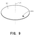
- FIG. 9 is a schematic perspective view of a discoid portion.
- FIG. 10 is a schematic cross sectional view of a fan including a rotor holder according to a third preferred embodiment of the present invention.
- FIG. 11 is a schematic bottom view of the rotor holder according to the third embodiment.
- FIG. 1 is a schematic cross sectional view of a fan 1 according to a first preferred embodiment of the present invention.
- the fan 1 preferably includes a housing 11 , a motor 3 , and a plurality of blades 21 arranged in a radial manner centered about a central axis J 1 .
- the fan 1 is used, for example, as a cooling fan which is used to cool electronic components and/or other heat generating elements in an electronic device.
- the housing 11 of the present preferred embodiment one of the sides when seen from above is approximately 40 mm.
- the motor 3 is preferably an outer rotor type motor including a stator portion 31 and a rotor portion 32 .
- the rotor portion 32 is preferably supported in a rotatable manner with respect to the stator portion 31 centered about the central axis J 1 .
- the stator portion 31 preferably includes a base portion 311 having a substantially discoid shape centered about the central axis J 1 .
- the base portion 311 is preferably affixed to the housing 11 via a plurality of ribs 3111 .
- the stator portion 31 preferably includes a bearing retaining portion 312 which includes a substantially cylindrical shape centered about the central axis J 1 and protrudes upwardly from the base portion 311 , and a sleeve 313 which is affixed to an inner side of the bearing retaining portion 312 and includes a substantially cylindrical shape centered about the central axis J 1 .
- the stator portion 31 preferably includes an armature 315 which is attached at an outer circumference of the bearing retaining portion 312 , and a circuit board 316 which is arranged below the armature 315 , includes a substantially annular shape, and is electrically connected to the armature 315 so as to control the drive current supplied to the armature 315 .
- the rotor portion 32 preferably includes a cup portion 321 which includes a substantially cylindrical shape with a lid centered about the central axis J 1 .
- the cup portion 321 preferably includes a rotor holder 322 which includes a substantially cylindrical shape with a lid centered about the central axis J 1 and is made of a magnetic metal material.
- the rotor holder 322 preferably includes a top plate portion 3221 which includes a substantially discoid shape centered about the central axis J 1 , and a side wall portion 3222 which includes a substantially cylindrical shape centered about the central axis J 1 and extends from an outer circumferential edge of the top plate portion 3221 in a downward direction substantially parallel with the central axis J 1 .
- the rotor holder 322 preferably includes a shaft support portion 3225 which includes a substantially cylindrical shape extending from a substantially central portion of the top plate portion 3221 in a downward direction at which a shaft 325 (described below) is inserted.
- a shaft support portion 3225 which includes a substantially cylindrical shape extending from a substantially central portion of the top plate portion 3221 in a downward direction at which a shaft 325 (described below) is inserted.
- an external diameter of the rotor holder 322 is approximately 22.4 mm and an internal diameter of the rotor holder 322 is approximately 21.4 mm.
- the cup portion 321 preferably includes a hub 323 which includes a substantially cylindrical shape made of a resin material and is affixed to the rotor holder 322 .
- the hub 323 preferably includes a hub top plate portion 3231 having a substantially annular shape centered about the central axis J 1 , and a hub side wall portion 3232 which includes a substantially cylindrical shape extending from an outer circumference of the hub top plate portion 3231 in a downward direction substantially parallel with the central axis J 1 .
- an outer circumferential surface of the side wall portion 3222 of the rotor holder 322 is preferably covered by the hub side wall portion 3232 .
- an area surrounding the outer circumferential edge of the top plate portion 3221 of the rotor holder 322 is preferably covered by the hub top plate portion 3231 .
- the plurality of blades 21 extend from the outer circumferential surface of the hub side wall portion 3232 in a radial direction centered about the central axis J 1 .
- the blades 21 and the hub 323 are preferably made of a same resin material in an integral manner as a single component.
- the rotor portion 32 is preferably affixed at an inner side of the side wall portion 3222 of the rotor holder 322 .
- the rotor portion 32 preferably includes a field magnet 324 having a substantially cylindrical shape radially opposed to the armature 315 , and the shaft 325 which is secured to the top plate portion 3221 of the rotor holder 322 extending in a downward direction from the top plate portion 3221 .
- the shaft 325 is preferably inserted into the sleeve 313 of the stator portion 31 and is rotatably supported by the sleeve 313 .
- the shaft 325 and the sleeve 313 preferably form a bearing mechanism supporting the cup portion 321 with respect to the base portion 311 in the rotatable manner centered about the central axis J 1 .
- a drive current is preferably supplied to the armature 315 via the circuit board 316 so as to generate a torque centered about the central axis J 1 between the armature 315 and the field magnet 324 arranged radially opposed thereto.
- the cup portion 321 which include the blades 21 arranged at the outer circumferential surface of the hub side wall portion 3232 and the shaft 325 rotate centered about the central axis J 1 .
- FIG. 2 is a schematic perspective view of the rotor holder 322 of the motor 3 . It is to be appreciated that FIGS. 2 , 4 C through 4 G, 7 and 12 depict the rotor holder 322 with a portion thereof notched in order to better show the configuration thereof.
- the rotor holder 322 preferably includes a side wall portion through hole 3224 arranged as a balance adjuster for the rotor holder 322 maintaining its weight balance in the axial direction and the circumferential direction at an area of the metal plate 90 corresponding to the bottom end portion of the side wall portion 3222 .
- the rotor holder 322 preferably includes a top plate portion through hole 3223 arranged as a balance adjuster for the rotor holder 322 maintaining its weight balance in the axial and circumferential direction at an area of the metal plate 90 corresponding to the outer circumferential edge of the top plate portion 3221 .
- the weight thereof in the axial direction and the circumferential direction is adjusted, whereby the weight balance thereof is adjusted (that is, the center of gravity is adjusted in accordance with the rotor holder 322 ).
- the rotor holder 322 is preferably formed from the metal plate 90 by pressing by a progressive die.
- the progressive die preferably includes a plurality of pairs of male and female dies which are arranged evenly apart from one another in a predetermined direction.
- the progressive die preferably moves the metal plate 90 , out of which the rotor holders 322 are formed, while multiple pressings are simultaneously executed.
- FIG. 3 is a flow chart illustrating a flow of steps taken to manufacture the rotor holder 322 .
- FIGS. 4A through 4G each are schematic perspective view of the rotor holder 322 during a manufacturing process thereof.
- FIGS. 5A and 5B each are schematic view of a portion of the progressive die which is used to manufacture the rotor holder 322 .
- FIG. 5A is a schematic plan view of a male die 811 which is used in step S 13 (see FIG. 3 , described below) of the manufacturing process described herein in which the side wall portion through hole 3224 (see FIG. 2 ) is arranged
- FIG. 5B is a schematic cross sectional view of the male die 811
- FIG. 5B denotes a central axis J 2 (which is coaxial with the central axis J 1 ) of the male die 811 , and a pin 812 (described below).
- the male die which is used to arrange the top plate portion through hole 3223 includes a configuration similar to that of the male die 811 .
- the male die 811 preferably includes a columnar portion 814 and a plurality of holes 815 at which pin 812 maybe arranged.
- the holes 815 are preferably arranged in a substantially concentric manner.
- the pin 812 may be arranged at at least any one of the holes 815 so as to arrange a through hole on the metal plate 90 for a desirable balance of the final product (i.e., rotor holder 322 ).
- the columnar portion 814 of the male die 811 may rotate centered about the central axis J 2 in order to adjust the position of the pin 812 .
- test rotor holder which includes no top plate portion through hole 3223 and the side wall portion through hole 3224 is formed by the progressive die in order to determine the weight balance thereof.
- the manufacturing process for the test rotor holder is identical with that (that is, steps S 12 to S 17 , described below) of the rotor holders 322 except that steps S 13 and S 15 are not carried out.
- the test rotor holder is tested in terms of its weight balance in the axial direction and its weight balance in the direction perpendicular to the axial direction. Then, based on the outcome of the test, locations (i.e., eccentric position in the axial and circumferential directions) and dimensions of the top plate portion through hole 3223 and the side wall portion through hole 3224 are determined.
- the pin 812 having the most appropriate diameter in accordance with the test outcome is selected and arranged at the male die 811 (see FIGS. 5A and 5B ) of the progressive die (step S 11 ).
- a distance between the hole 815 at which the pin 812 is arranged and the central axis J 2 of the male die 811 is determined in accordance with the position of the side wall portion through hole 3224 to be arranged in the final product with respect to the central axis J 1 .
- the metal plate 90 shown in FIG. 4A is supplied to the progressive die in which an area surrounding each of a plurality of discoid portions 91 (see FIGS. 4A and 4B ) is all but removed.
- the discoid portions 91 are sequentially formed while the metal plate 90 and the portions thereof to be the rotor holder 322 remain connected (step S 12 ).
- the male die 811 and the corresponding female die (not shown) to the discoid portion 91 .
- a portion near the outer circumferential edge of the discoid portion 91 at the metal plate 90 that is a portion corresponding to the side wall portion 3222 of the rotor holder 322 will be punched out.
- the first punched portion 914 which is a through hole having a substantially round shape is formed at the portion corresponding to the side wall portion through hole 3224 (step S 13 ).
- a substantially platelike stripper plate (not shown) is arranged between the metal plate 90 and the corresponding female die in order to facilitate the pressing procedure.
- first punched portion 914 may be formed at the same time the discoid portion 91 is formed (i.e., step S 12 ). Also note that a second punched portion (described below) which is arranged at a portion of the metal plate 90 corresponding to the top plate portion through hole 3223 may be formed at the same time the first punched portion 914 is formed.
- the metal plate 90 is moved so that the discoid portion 91 is arranged at the next position of the progressive die. Then, a first drawing is carried out to the discoid portion 91 in order to form the top plate portion 3221 and the side wall portion 3222 of the rotor holder 322 as shown in FIG. 4C . Then, the rotor holder 322 is moved to a following die for a second and third drawing in order to form the top plate portion 3221 and the side wall portion 3222 as shown in FIGS. 4D and 4E (step S 14 ).
- the first punched portion 914 and a portion surrounding the first punched portion 914 will be deformed due to the aforementioned drawings.
- the first punched portion 914 becomes longer in the axial direction and shorter in the radial direction as shown in FIG. 6 .
- the first punched portion 914 after being deformed due to the drawings as described above will be referred to as the side wall portion through hole 3224 having a substantially oval shape.
- FIG. 6 is a schematic enlarged view of the side wall portion through hole 3224 and its surrounding area arranged at the side wall portion 3222 of the rotor holder 322 .
- a metal grain flow 3227 in a direction substantially parallel with the axial direction is formed at the side wall portion 3222 due to drawing procedures as described above.
- the area surrounding the first punched portion 914 is deformed such that the metal grain flow 3227 is deformed accordingly.
- a portion of the metal grain flow 3227 which is deformed toward substantially the center of the first punched portion 914 will be referred to as the metal grain flow centered portion 3228 .
- the metal grain flow 3227 is curved toward the side wall portion through hole 3224 at the metal grain flow centered portion 3228 , a space between the vertical lines of the metal grain flow 3227 shown in FIG. 6 is widened at the axially central area of the side wall portion through hole 3224 . Also, a space between the vertical line of the metal grain flow 3227 is narrowed at axial ends of the side wall portion through hole 3224 . It is to be appreciated that depending on a level of pressure applied to the metal plate 90 , the pattern of the metal grain flow 3227 may be varied.
- the second punched portion i.e., the top plate portion through hole 3223
- an opening is arranged at a substantially central area of the top plate portion 3221 , and a burring is carried out thereto so as to form the shaft support portion 3225 (step S 16 ).
- the shaft support portion 3225 preferably includes a substantially cylindrical shape and protrudes downwardly.
- an annular portion 3226 (see FIG. 4F ) preferably extending from a lower end of the side wall portion 3222 in a perpendicular manner with respect to the central axis J 1 is removed therefrom by trimming or the like so as to remove the side wall portion 3222 as shown in FIG. 4G from the metal plate 90 (see FIG. 4A ) thereby completing the forming of the rotor holder 322 (step S 17 ).
- the rotor holder 322 including the top plate portion 3221 and the side wall portion 3222 is formed by performing a series of pressings on the metal plate 90 by the progressive die.
- the side wall portion through hole 3224 is formed by performing a series of pressings by the progressive die.
- the top plate portion through hole 3223 is effectively and speedily formed at the top plate portion 3221 while manufacturing the rotor holder 322 by the progressive die. Consequently, a rotor holder having a good balance in the circumferential direction is effectively and speedily manufactured. Also, the weight balance of the rotor holder 322 in terms of the axial and circumferential directions is achieved by the side wall portion through hole 3224 and the top plate portion through hole 3223 .
- the rotor holder 322 which is manufactured as described above is operable to rotate concentrically with the central axis J 1 of the rotor holder 322 , vibrations potentially caused by an unbalanced rotor holder 322 when the rotor portion 32 rotates are minimized.
- a center of rotation of the rotor portion 32 having the blades 21 preferably and substantially aligns with a center of dynamic pressure generated at a radial bearing portion which is a bearing unit of the fan 1 when the motor 3 rotates. Consequently, vibrations of the rotor holder 322 are minimized.
- the field magnet 324 which is arranged at an inner circumferential surface of the side wall portion 3222 of the rotor holder 322 is arranged at a corresponding portion of the inner circumferential surface of the side wall portion 3222 so as to compensate for the misalignment. Consequently, vibrations of the rotor holder 322 are minimized.
- the hub 323 which is formed integrally as a single member with the blades 21 is affixed at the outer circumferential surface of the side wall portion 3222 , the hub 323 including the blades 21 is arranged so as to compensate for the misalignment of the rotor holder 322 in order to achieve the balance of the fan 1 . Consequently, vibrations of the rotor holder 322 are minimized.
- the top plate portion through hole 3223 and the side wall portion through hole 3224 are used as reference point. Therefore, an additional reference point will not be required at the rotor holder 322 which simplifies the manufacturing process of the motor 3 and the fan 1 .
- the side wall portion through hole 3224 is preferably arranged at the bottom end portion of the side wall portion 3222 . It is to be appreciated that when a distance between the side wall portion through hole 3224 and the top plate portion through hole 3223 in the axial direction is great as described above, the axial weight balance of the rotor holder 322 is improved.
- the circumferential width of the first punched portion 914 is modified by step S 14 so as to reduce the dimension of the side wall portion through hole 3224 .
- leakage of a magnetic flux from the field magnet 324 via the side wall portion through hole 3224 is minimized, whereby improving the characteristics of the motor 3 .
- the application of the adhesive may be carried out freely.
- a transfer press die may be used instead of the above described progressive die.
- the transfer press die the plurality of rotor holders 322 are manufactured speedily and accurately.
- a configuration of the fan 1 A is substantially identical with that of the fan 1 according to the second preferred embodiment except that the fan 1 A includes no side wall portion through hole at a side wall portion of a rotor holder thereof. Note that in the description of the second preferred embodiment herein, elements similar to those described in the first preferred embodiment are denoted by similar reference numerals, and description thereof is omitted.
- FIG. 7 is a schematic perspective view of a rotor holder 322 a of the fan 1 A according to the second preferred embodiment. Note that according to the rotor holder 322 a , a portion surrounding the first punched portion 914 is deformed toward substantially the center of the first punched portion 914 during the drawing carried out in step S 14 such that the first punched portion 914 is substantially closed. That is, the first punched portion 914 is substantially open as a passage of air or the like, however, is substantially closed for naked eyes to recognize it as a hole.
- FIG. 8 is a schematic enlarged view of a portion of the side wall portion 3222 of the rotor holder 322 a corresponding to the first punched portion 914 .
- a broken line shown in FIG. 8 indicates the portion of the side wall portion 3222 at which the first punched portion 914 was arranged and was substantially closed.
- FIG. 8 also shows the metal grain flow 3227 by a plurality of substantially vertical lines. As shown in FIG. 8 , the metal grain flow 3227 is substantially parallel with the central axis J 1 at the side wall portion 3222 , and is deformed toward substantially the center of the first punched portion 914 at the portion near the first punched portion 914 .
- the area surrounding the first punched portion 914 is deformed such that the metal grain flow 3227 is deformed accordingly.
- a portion of the metal grain flow 3227 which is deformed toward substantially the center of the first punched portion 914 will be referred to as the metal grain flow centered portion 3228 .
- the rotor holder 322 a includes the metal grain flow centered portion 3228 and the top plate portion through hole 3223 , the weight thereof in the axial direction and the circumferential direction is adjusted, whereby the weight balance thereof is adjusted (that is, the center of gravity is adjusted in accordance with the rotor holder 322 ).
- a transfer press die may be used instead of the above described progressive die.
- the metal grain flow centered portion 3228 which is used to adjust the weight balance of the rotor holder 322 a is formed at the corresponding portion of the side wall portion 3222 effectively during the pressing processes on the metal plate by the progressive die.
- the rotor holder 322 a which is well-balanced in the circumferential direction is manufactured effectively.
- the top plate portion through hole 3223 is properly arranged at the corresponding portion of the top plate portion 3221 effectively. By this, the rotor holder 322 a which is well-balanced in the circumferential and axial directions is manufactured effectively.
- the metal grain flow centered portion 3228 is arranged at the bottom end portion of the side wall portion 3222 .
- the rotor holder 322 a having the metal grain flow centered portion 3228 and the top plate portion through hole 3223 is operable to achieve the proper axial weight balance.
- the circumferential width of the first punched portion 914 may be reduced by the drawing process.
- the characteristics of the motor 3 is improved in that the magnetic flux of the field magnet 324 will be prevented from leaking out of the side wall portion 3222 .
- the application of the adhesive may be carried out freely.
- the first punched portion 914 formed at the discoid portion 91 in step S 13 may include a substantially oval shape as shown in FIG. 9 in which case, it becomes easier to securely close the circumferential width of the first punched portion 914 during the drawing process.
- FIG. 10 is a schematic cross sectional view of the fan B according to the third preferred embodiment.
- a configuration of the fan B is substantially identical with that of the fan 1 according to the fan 1 shown in FIG. 1 except that the fan B includes a cup portion 321 a which is shaped differently than the cup portion 321 of the fan 1 .
- elements similar to those described in the first preferred embodiment are denoted by similar reference numerals, and description thereof is omitted.
- the cup portion 321 a of the fan B preferably includes a rotor holder 322 b which includes a substantially cylindrical shape centered about the central axis J 1 and is made of a magnetic metal material, and a hub 323 which includes a substantially cylindrical shape, is made of a resin material and is affixed to the rotor holder 322 b .
- the rotor holder 322 b preferably includes a top plate portion 3221 a having a substantially annular shape centered about the central axis J 1 , and a side wall portion 3222 which includes a substantially cylindrical shape extending from an outer circumferential edge of the top plate portion 3221 a in a downward direction substantially parallel with the central axis J 1 .
- the hub 323 a preferably includes a hub top plate portion 3231 a having a substantially annular shape centered about the central axis J 1 , and a hub side wall portion 3232 which includes a substantially cylindrical shape extending from an outer circumference of the hub top plate portion 3231 a in a downward direction substantially parallel with the central axis J 1 . Also, the hub 323 a preferably includes a shaft support portion 3235 which includes a substantially cylindrical shape extending from a substantially central portion of the hub top plate portion 3231 a at which the shaft 325 is arranged.
- FIG. 11 is a schematic bottom view of the rotor holder 322 b according to the present preferred embodiment.
- the rotor holder 322 b preferably includes a top plate notched portion 3223 a which is arranged at an inner circumferential edge of the top plate portion 3221 a so as to achieve the proper weight balance of the rotor holder 322 b in the axial and circumferential directions.
- the rotor holder 322 b may also include, in the same manner as in the first preferred embodiment, the side wall portion through hole 3224 (see FIG. 2 ).
- the rotor holder 322 b of the present preferred embodiment includes the side wall portion through hole 3224 and the top plate notched portion 3223 a , the weight thereof is reduced, and therefore, the weight balance thereof is adjusted in the circumferential and axial directions.
- the manufacturing method of the rotor holder 322 b is substantially identical with that of the first embodiment (see FIG. 3 ) except that a substantially round hole is arranged at a substantially central portion of the discoid portion 91 prior to step S 15 in which a second punched portion becomes the top plate notched portion 3223 a . Note that the hole at the central portion of the discoid portion 91 and the second punched portion mentioned above may be formed at the same time.
- the manufacturing method of the rotor holder 322 b of the third preferred embodiment the side wall portion through hole 3224 and the top plate notched portion 3223 a are respectively arranged at the side wall portion 3222 and the top plate portion 3221 a by the progressive die by the progressive die so as to achieve the weight balance of the rotor holder 322 b in the axial direction and the circumferential directions in an effective manner.
- first punched portion 914 and the second punched portion at the metal plate 90 are described above, the present invention is not limited thereto.
- the locations of the first punched portion 914 and the second punched portion may be varied depending on the size, shape, and material of the rotor holder.
- the side wall portion 3222 may be formed at the same time the top plate portion 3221 is formed. Also, the second punched portion may be formed at the same as the first punched portion is formed.
- the present invention is not limited thereto.
- the present invention is not limited thereto.
- the present invention is not limited thereto.
- the bearing mechanism includes the radial bearing
- the present invention is not limited thereto.
- the present invention may include a fluid dynamic pressure bearing.
Landscapes
- Engineering & Computer Science (AREA)
- Power Engineering (AREA)
- Manufacturing & Machinery (AREA)
- Manufacture Of Motors, Generators (AREA)
- Connection Of Motors, Electrical Generators, Mechanical Devices, And The Like (AREA)
- Motor Or Generator Frames (AREA)
- Permanent Magnet Type Synchronous Machine (AREA)
Abstract
Description
Claims (8)
Applications Claiming Priority (2)
| Application Number | Priority Date | Filing Date | Title |
|---|---|---|---|
| JP2007-168658 | 2007-06-27 | ||
| JP2007168658A JP5170822B2 (en) | 2007-06-27 | 2007-06-27 | Rotor holder, motor and blower fan, and method for manufacturing rotor holder |
Publications (2)
| Publication Number | Publication Date |
|---|---|
| US20090001825A1 US20090001825A1 (en) | 2009-01-01 |
| US8074344B2 true US8074344B2 (en) | 2011-12-13 |
Family
ID=40159541
Family Applications (1)
| Application Number | Title | Priority Date | Filing Date |
|---|---|---|---|
| US12/145,528 Expired - Fee Related US8074344B2 (en) | 2007-06-27 | 2008-06-25 | Method of manufacturing rotor holder |
Country Status (3)
| Country | Link |
|---|---|
| US (1) | US8074344B2 (en) |
| JP (1) | JP5170822B2 (en) |
| CN (1) | CN101409484B (en) |
Cited By (3)
| Publication number | Priority date | Publication date | Assignee | Title |
|---|---|---|---|---|
| US20120114503A1 (en) * | 2010-03-31 | 2012-05-10 | Zhongshan Broad-Ocean Motor Co., Ltd. | Locking device |
| US20130078123A1 (en) * | 2011-09-28 | 2013-03-28 | Kabushiki Kaisha Toyota Jidoshokki | Electric motor for a motor-driven compressor and said motor-driven compressor |
| US20130200913A1 (en) * | 2012-02-06 | 2013-08-08 | Peter G. Panagas | Testing System with Test Trays |
Families Citing this family (9)
| Publication number | Priority date | Publication date | Assignee | Title |
|---|---|---|---|---|
| JP2010239858A (en) * | 2009-03-12 | 2010-10-21 | Nippon Densan Corp | Motor |
| TWI418707B (en) * | 2010-09-03 | 2013-12-11 | Delta Electronics Inc | Fan and manufacturing method therefor |
| JP5943291B2 (en) | 2011-06-30 | 2016-07-05 | 日本電産株式会社 | Bearing device and blower fan |
| JP2014145304A (en) * | 2013-01-29 | 2014-08-14 | Nippon Densan Corp | Blower fan |
| US9917488B2 (en) * | 2014-03-04 | 2018-03-13 | Nidec Motor Corporation | Motor including removable weights for balancing |
| JP5833271B1 (en) | 2015-08-26 | 2015-12-16 | ニッタ株式会社 | IC tag container and rubber product with IC tag provided with the same |
| JP6478901B2 (en) | 2015-11-30 | 2019-03-06 | ニッタ株式会社 | IC tag, IC tag container and rubber product with IC tag |
| CN107147226B (en) * | 2016-03-01 | 2022-01-25 | 雷勃澳大利亚私人有限公司 | Rotor, motor and related method |
| GB201719053D0 (en) | 2017-11-17 | 2018-01-03 | Cummins Generator Technologies | Excitation system |
Citations (13)
| Publication number | Priority date | Publication date | Assignee | Title |
|---|---|---|---|---|
| US3844031A (en) * | 1973-08-15 | 1974-10-29 | Gen Electric | Method of mounting and forming dynamoelectric machine components |
| JPS6474049A (en) | 1987-09-11 | 1989-03-20 | Seiko Electronic Components | Rotor shape for brushless motor |
| JPH01152136A (en) | 1987-12-10 | 1989-06-14 | Nippon Oil Co Ltd | Evaluation of bonding strength of surface-oxidized carbon fiber |
| JPH01154350A (en) | 1987-12-09 | 1989-06-16 | Mitsubishi Electric Corp | Tape cassette loading mechanism of tape player |
| JPH03126341A (en) | 1989-10-11 | 1991-05-29 | Nec Corp | Path monitor method |
| JPH05252704A (en) | 1992-03-06 | 1993-09-28 | Mitsubishi Electric Corp | Rotor balance adjustment method |
| JPH0713095A (en) | 1993-06-28 | 1995-01-17 | Fuji Xerox Co Ltd | Rotating body, driving motor for driving this rotating body, and rotating polygon mirror device including rotating polygon mirror, and method for correcting rotational balance of rotating body |
| JPH0775301A (en) | 1993-08-31 | 1995-03-17 | Toshiba Lighting & Technol Corp | Brushless motor and laser printer |
| JPH09308153A (en) * | 1996-05-09 | 1997-11-28 | Matsushita Electric Ind Co Ltd | Method of manufacturing rotor frame for spindle motor |
| JP3126341B2 (en) | 1998-02-05 | 2001-01-22 | 日本サーボ株式会社 | Axial fan rotor |
| JP2002039096A (en) | 2000-07-27 | 2002-02-06 | Minebea Co Ltd | Air blower |
| JP2002142392A (en) | 2000-11-06 | 2002-05-17 | Matsushita Electric Ind Co Ltd | Permanent magnet type electric motor and electric equipment using the same |
| JP2004159421A (en) | 2002-11-06 | 2004-06-03 | Matsushita Electric Ind Co Ltd | Small axial fan motor |
Family Cites Families (9)
| Publication number | Priority date | Publication date | Assignee | Title |
|---|---|---|---|---|
| JPS60151279U (en) * | 1984-03-16 | 1985-10-08 | 株式会社東芝 | motor rotor |
| JP2931044B2 (en) * | 1990-05-31 | 1999-08-09 | 日本電産株式会社 | Rotary body manufacturing equipment |
| JP2002095228A (en) * | 2000-09-14 | 2002-03-29 | Sankyo Seiki Mfg Co Ltd | Motor |
| JP2002272069A (en) * | 2001-03-13 | 2002-09-20 | Hitachi Ltd | Disk motor and optical disk device using the same |
| FR2855671B1 (en) * | 2003-05-26 | 2005-12-02 | Valeo Equip Electr Moteur | ROTATING ELECTRIC MACHINE COMPRISING A FAN |
| JP4467041B2 (en) * | 2003-11-10 | 2010-05-26 | 日本電産株式会社 | Centrifugal fan |
| CN100474743C (en) * | 2004-01-29 | 2009-04-01 | 皇家飞利浦电子股份有限公司 | Method of balancing an suction unit comprising a ventilator and an electric motor |
| JP4622365B2 (en) * | 2004-07-27 | 2011-02-02 | 船井電機株式会社 | Axial fan |
| JP2006057568A (en) * | 2004-08-23 | 2006-03-02 | Sanden Corp | Scroll type expander |
-
2007
- 2007-06-27 JP JP2007168658A patent/JP5170822B2/en not_active Expired - Fee Related
-
2008
- 2008-06-25 US US12/145,528 patent/US8074344B2/en not_active Expired - Fee Related
- 2008-06-27 CN CN2008102103115A patent/CN101409484B/en not_active Expired - Fee Related
Patent Citations (16)
| Publication number | Priority date | Publication date | Assignee | Title |
|---|---|---|---|---|
| US3844031A (en) * | 1973-08-15 | 1974-10-29 | Gen Electric | Method of mounting and forming dynamoelectric machine components |
| JPS6474049A (en) | 1987-09-11 | 1989-03-20 | Seiko Electronic Components | Rotor shape for brushless motor |
| JPH01154350A (en) | 1987-12-09 | 1989-06-16 | Mitsubishi Electric Corp | Tape cassette loading mechanism of tape player |
| JPH01152136A (en) | 1987-12-10 | 1989-06-14 | Nippon Oil Co Ltd | Evaluation of bonding strength of surface-oxidized carbon fiber |
| JPH03126341A (en) | 1989-10-11 | 1991-05-29 | Nec Corp | Path monitor method |
| JPH05252704A (en) | 1992-03-06 | 1993-09-28 | Mitsubishi Electric Corp | Rotor balance adjustment method |
| JPH0713095A (en) | 1993-06-28 | 1995-01-17 | Fuji Xerox Co Ltd | Rotating body, driving motor for driving this rotating body, and rotating polygon mirror device including rotating polygon mirror, and method for correcting rotational balance of rotating body |
| JPH0775301A (en) | 1993-08-31 | 1995-03-17 | Toshiba Lighting & Technol Corp | Brushless motor and laser printer |
| JPH09308153A (en) * | 1996-05-09 | 1997-11-28 | Matsushita Electric Ind Co Ltd | Method of manufacturing rotor frame for spindle motor |
| JP3126341B2 (en) | 1998-02-05 | 2001-01-22 | 日本サーボ株式会社 | Axial fan rotor |
| JP2002039096A (en) | 2000-07-27 | 2002-02-06 | Minebea Co Ltd | Air blower |
| US20020047384A1 (en) | 2000-07-27 | 2002-04-25 | Minebea Co., Ltd. | Blower |
| US20030184168A1 (en) | 2000-07-27 | 2003-10-02 | Minebea Co., Ltd. | Blower |
| US20040191088A1 (en) | 2000-07-27 | 2004-09-30 | Minebea Co., Ltd. | Blower |
| JP2002142392A (en) | 2000-11-06 | 2002-05-17 | Matsushita Electric Ind Co Ltd | Permanent magnet type electric motor and electric equipment using the same |
| JP2004159421A (en) | 2002-11-06 | 2004-06-03 | Matsushita Electric Ind Co Ltd | Small axial fan motor |
Non-Patent Citations (2)
| Title |
|---|
| Machine Translation of JP09308153, obtained Feb. 13, 2011. * |
| Tabata et al.; "Rotor Yoke and Balance Adjusting Method Thereof"; U.S. Appl. No. 12/468,123, filed May 19, 2009. |
Cited By (6)
| Publication number | Priority date | Publication date | Assignee | Title |
|---|---|---|---|---|
| US20120114503A1 (en) * | 2010-03-31 | 2012-05-10 | Zhongshan Broad-Ocean Motor Co., Ltd. | Locking device |
| US8523528B2 (en) * | 2010-03-31 | 2013-09-03 | Zhongshan Broad-Ocean Motor Co., Ltd. | Locking device |
| US20130078123A1 (en) * | 2011-09-28 | 2013-03-28 | Kabushiki Kaisha Toyota Jidoshokki | Electric motor for a motor-driven compressor and said motor-driven compressor |
| US9188115B2 (en) * | 2011-09-28 | 2015-11-17 | Kabushiki Kaisha Toyota Jidoshokki | Electric motor for a motor-driven compressor and said motor-driven compressor |
| US20130200913A1 (en) * | 2012-02-06 | 2013-08-08 | Peter G. Panagas | Testing System with Test Trays |
| US9423420B2 (en) * | 2012-02-06 | 2016-08-23 | Apple Inc. | Testing system with test trays |
Also Published As
| Publication number | Publication date |
|---|---|
| JP5170822B2 (en) | 2013-03-27 |
| CN101409484B (en) | 2011-06-01 |
| US20090001825A1 (en) | 2009-01-01 |
| JP2009011041A (en) | 2009-01-15 |
| CN101409484A (en) | 2009-04-15 |
Similar Documents
| Publication | Publication Date | Title |
|---|---|---|
| US8074344B2 (en) | Method of manufacturing rotor holder | |
| CN104052226B (en) | DC brushless motor | |
| JP5943291B2 (en) | Bearing device and blower fan | |
| US8899946B2 (en) | Fan having a balance correction portion | |
| US7626305B2 (en) | Armature, motor using the armature, and disk drive device using the motor | |
| US9140268B2 (en) | Bearing apparatus and blower fan | |
| CN108110953A (en) | Motor | |
| US20130257189A1 (en) | Balanced rotor for a rotation machine, and method for balancing a rotor | |
| US11316402B2 (en) | Rotor and motor including same | |
| CN103821762A (en) | Impeller and electric blower having the same | |
| CN102628448A (en) | Blower fan | |
| US20070080604A1 (en) | Electric fan | |
| CN107476994B (en) | Air supply device | |
| JP6972890B2 (en) | Motors and motor manufacturing methods | |
| CN108427491B (en) | Heat radiation fan and electronic device with same | |
| EP0310391B1 (en) | Axial flow fan | |
| US11577308B2 (en) | Die casting apparatus provided with movable electromagnetically controlled structure control module | |
| US20020158544A1 (en) | External rotor cup with annular flange extending therefrom | |
| CN202833224U (en) | Centrifugal fan | |
| JP6897180B2 (en) | How to manufacture the rotor housing | |
| US20100074747A1 (en) | Mini axial fan with an improved core shaft structure | |
| US20140169966A1 (en) | Magnet case and rotor incorporating the same | |
| KR20190016768A (en) | ROTOR AND Motor HAVING THE SAME | |
| EP0905865A2 (en) | Method of assembling magnetic disk driving motor | |
| JP4103767B2 (en) | Compressor |
Legal Events
| Date | Code | Title | Description |
|---|---|---|---|
| AS | Assignment |
Owner name: NIDEC CORPORATION, JAPAN Free format text: ASSIGNMENT OF ASSIGNORS INTEREST;ASSIGNORS:HANAOKA, SATORU;SUGIYAMA, TOMOTSUGU;TABATA, SHINYA;AND OTHERS;REEL/FRAME:021167/0690;SIGNING DATES FROM 20080616 TO 20080618 Owner name: NIDEC CORPORATION, JAPAN Free format text: ASSIGNMENT OF ASSIGNORS INTEREST;ASSIGNORS:HANAOKA, SATORU;SUGIYAMA, TOMOTSUGU;TABATA, SHINYA;AND OTHERS;SIGNING DATES FROM 20080616 TO 20080618;REEL/FRAME:021167/0690 |
|
| ZAAA | Notice of allowance and fees due |
Free format text: ORIGINAL CODE: NOA |
|
| ZAAB | Notice of allowance mailed |
Free format text: ORIGINAL CODE: MN/=. |
|
| ZAAA | Notice of allowance and fees due |
Free format text: ORIGINAL CODE: NOA |
|
| STCF | Information on status: patent grant |
Free format text: PATENTED CASE |
|
| FEPP | Fee payment procedure |
Free format text: PAYOR NUMBER ASSIGNED (ORIGINAL EVENT CODE: ASPN); ENTITY STATUS OF PATENT OWNER: LARGE ENTITY |
|
| FPAY | Fee payment |
Year of fee payment: 4 |
|
| MAFP | Maintenance fee payment |
Free format text: PAYMENT OF MAINTENANCE FEE, 8TH YEAR, LARGE ENTITY (ORIGINAL EVENT CODE: M1552); ENTITY STATUS OF PATENT OWNER: LARGE ENTITY Year of fee payment: 8 |
|
| FEPP | Fee payment procedure |
Free format text: MAINTENANCE FEE REMINDER MAILED (ORIGINAL EVENT CODE: REM.); ENTITY STATUS OF PATENT OWNER: LARGE ENTITY |
|
| LAPS | Lapse for failure to pay maintenance fees |
Free format text: PATENT EXPIRED FOR FAILURE TO PAY MAINTENANCE FEES (ORIGINAL EVENT CODE: EXP.); ENTITY STATUS OF PATENT OWNER: LARGE ENTITY |
|
| STCH | Information on status: patent discontinuation |
Free format text: PATENT EXPIRED DUE TO NONPAYMENT OF MAINTENANCE FEES UNDER 37 CFR 1.362 |
|
| FP | Lapsed due to failure to pay maintenance fee |
Effective date: 20231213 |