US8072858B2 - Optical disk apparatus, control method of optical disk apparatus, and integrated circuit - Google Patents
Optical disk apparatus, control method of optical disk apparatus, and integrated circuit Download PDFInfo
- Publication number
- US8072858B2 US8072858B2 US12/162,196 US16219607A US8072858B2 US 8072858 B2 US8072858 B2 US 8072858B2 US 16219607 A US16219607 A US 16219607A US 8072858 B2 US8072858 B2 US 8072858B2
- Authority
- US
- United States
- Prior art keywords
- signal
- unit
- rotational phase
- detection unit
- lens position
- Prior art date
- Legal status (The legal status is an assumption and is not a legal conclusion. Google has not performed a legal analysis and makes no representation as to the accuracy of the status listed.)
- Expired - Fee Related, expires
Links
Images


Classifications
-
- G—PHYSICS
- G11—INFORMATION STORAGE
- G11B—INFORMATION STORAGE BASED ON RELATIVE MOVEMENT BETWEEN RECORD CARRIER AND TRANSDUCER
- G11B7/00—Recording or reproducing by optical means, e.g. recording using a thermal beam of optical radiation by modifying optical properties or the physical structure, reproducing using an optical beam at lower power by sensing optical properties; Record carriers therefor
- G11B7/08—Disposition or mounting of heads or light sources relatively to record carriers
- G11B7/09—Disposition or mounting of heads or light sources relatively to record carriers with provision for moving the light beam or focus plane for the purpose of maintaining alignment of the light beam relative to the record carrier during transducing operation, e.g. to compensate for surface irregularities of the latter or for track following
- G11B7/095—Disposition or mounting of heads or light sources relatively to record carriers with provision for moving the light beam or focus plane for the purpose of maintaining alignment of the light beam relative to the record carrier during transducing operation, e.g. to compensate for surface irregularities of the latter or for track following specially adapted for discs, e.g. for compensation of eccentricity or wobble
- G11B7/0953—Disposition or mounting of heads or light sources relatively to record carriers with provision for moving the light beam or focus plane for the purpose of maintaining alignment of the light beam relative to the record carrier during transducing operation, e.g. to compensate for surface irregularities of the latter or for track following specially adapted for discs, e.g. for compensation of eccentricity or wobble to compensate for eccentricity of the disc or disc tracks
Definitions
- the present invention is related to an optical disk apparatus and the like which causes an optical beam to follow an eccentricity of a track when recording or reproducing information on a recordable disk-shaped information carrier (hereinafter referred to as an “optical disk”).
- the reproduction of a signal is performed by irradiating an optical beam having a constant and relatively low light intensity on an optical disk that is an information carrier, and detecting reflected light modulated by an information recording surface of the optical disk as high/low light intensities.
- information is written on a recording material film on the optical disk by modulating an optical beam as high/low light intensities according to the signal to be recorded.
- Recording information on an optical disk or reproducing information recorded on an optical disk requires focusing control in which an optical beam is controlled in a normal direction (hereinafter referred to as a “focusing direction”) of a face of an optical disk 1 so that the optical beam is constantly in a predetermined focused state on the recording material film as well as tracking control in which the optical beam is controlled in a radial direction (hereinafter referred to as a “tracking direction”) of the optical disk so that the optical beam is constantly positioned on a predetermined track.
- tracking control involves detecting high/low levels of reflected light from an information recording surface including tracks of an optical disk as a tracking error signal, and based thereon, moving an objective lens for collecting the optical beam on the optical disk in a tracking direction.
- a track of an optical disk is formed in a spiral-shape on an information recording surface.
- a row of pits is formed in a spiral shape.
- a guiding groove is formed in a spiral shape, and an optically recordable or readable material film is further formed using a method such as deposition on a substrate surface on which irregularities are formed by the guiding groove.
- a process for fabricating pits or a guiding groove including track information on a reflection surface of light from an optical head 10 by press working or the like is independent from a subsequently-performed process for fabricating a central hole for clamping.
- the center of the spiral of a track is not completely consistent with the center of the central hole of the optical disk, thereby causing eccentricity during clamping of the optical disk.
- Such an eccentricity acts as a primary periodic disturbance component of the optical disk apparatus and significantly reduces following performance with respect to tracks.
- optical disks 1 capable of high density recording in order to record large volumes of information including visual information as well as optical disk apparatuses capable of recording or reproducing information from such optical disks at high speed have come into use.
- control of a movement of an objective lens in a tracking-direction for the purpose of compensating disk eccentricity is being performed independently of normal tracking control (for example, refer to Japanese Patent Laid-Open No. 2005-182968).
- FIG. 16( a ) is a block configuration diagram of an optical disk apparatus which performs such control.
- an optical head 10 is mounted with a semiconductor laser 11 , a collecting lens 13 , a beam splitter 12 , an Fc actuator 14 , a Tk actuator 15 and a light detector 16 .
- An optical beam generated from the semiconductor laser 11 passes through the beam splitter 12 and is focused above a disk-shaped optical disk 1 by the collecting lens 13 .
- the optical beam reflected off the optical disk 1 once again passes through the collecting lens 13 and is reflected off the beam splitter 12 and irradiated to the light detector 16 .
- the collecting lens 13 is supported by an elastic body (not shown) and moves in a focusing direction due to an electromagnetic force when an electric current is passed through the Fc actuator 14 .
- the collecting lens 13 moves in a tracking direction due to an electromagnetic force when an electric current is passed through the Tk actuator 15 .
- the light detector 16 generates a signal according to a detected light intensity.
- the light detector 16 sends the signal to an LE signal generator 30 .
- the LE signal generator 30 uses the light intensity signal of the light detector 16 to compute a position signal (lens shift error signal: hereinafter referred to as an “LE signal”) with respect to the optical head 10 of the collecting lens 13 , and sends the same to an LE signal filter 37 via a subtractor 35 .
- an LE signal can be generated by performing a sample/hold or the like on a push-pull tracking error detection signal acquired from a reflected light from the optical disk 1 .
- the LE signal generator 30 uses a top hold push-pull method in which are acquired respective pick/hold signals of signals from which push-pull method tracking error signals are obtained by mutual subtraction processing, whereby the pick/hold signals are subtracted from each other. Due to such a configuration, the influence of reflected light from the tracks is eliminated. (For example, refer to Japanese Patent Laid-Open No. H09-274726).
- the LE signal filter 37 In response to a signal from the LE signal generator 30 , the LE signal filter 37 generates a signal for performing lens control and sends the same to a drive circuit 73 , whereby the drive circuit 73 drives the Tk actuator 15 .
- a disk motor 20 rotates the optical disk 1 , generates a predetermined pulse signal (hereinafter referred to as an “FG signal”) during one rotation and sends the same to a rotational phase detector 21 .
- FG signal a predetermined pulse signal
- the rotational phase detector 21 generates a rotational phase of the optical disk 1 by counting FG signals from the disk motor 20 and sends the same to an LE signal memory regenerator 32 and an LE signal memory recorder 31 .
- the LE signal memory recorder 31 records an LE signal of the LE signal generator 30 for each rotational phase on the LE signal memory 33 .
- the LE signal memory 33 retains an LE signal level for each rotational phase. Every time rotational phase information from the rotational phase detector 21 changes during an eccentricity correction recording operation, the LE signal memory regenerator 32 selects an LE signal level corresponding to the rotational phase from the LE signal memory 33 in synchronization to the change and sends the selected LE signal level to the subtractor 35 .
- the subtractor 35 subtracts the signal from the LE signal memory regenerator 32 from the signal from the LE signal generator 30 and sends the subtracted signal to the LE signal filter 37 .
- the LE signal filter 37 Upon receiving the signal of the subtractor 35 , the LE signal filter 37 generates a drive signal whose target value is the stored information of the LE signal memory 33 .
- the drive circuit 73 receives the drive signal and passes a current through the Tk actuator 15 , and moves the Tk actuator 15 in a tracking direction. Consequently, the optical beam is adapted to follow the eccentricity of the optical disk 1 .
- the aforementioned lens control with feedback using a lens shift amount mainly becomes necessary when the optical head 10 performs a long-distance seek that strides a plurality of tracks at one time, and is performed when drive signals inputted to the drive circuit 73 are switched by an operation of a change-over switch 72 .
- Normal tracking control is performed as follows. That is, the light detector 16 detects reflected light from a pit row or the like formed on an information recording surface of the optical disk 1 .
- a TE signal generator 70 generates a tracking error signal (hereinafter “TE signal”) based on the signal detected by the light detector 16 .
- a TE signal filter 71 Upon receiving the TE signal, a TE signal filter 71 generates a drive signal based thereon and sends it to the drive circuit 73 .
- the drive circuit 73 passes a current in accordance with the drive signal and moves the Tk actuator 15 .
- a signal from the LE signal memory regenerator 32 assumes a staircase form corresponding to a count value t of an FG signal as shown in FIG. 17( b ).
- a rising edge portion or a trailing edge portion of steps of the staircase waveform of the signal from the LE signal memory regenerator 32 includes a high-frequency band signal component. Therefore, even when a difference between both signals is obtained by the subtractor 35 , the signal waveform of the difference assumes a staircase form.
- the LE signal filter 37 for performing lens control is configured as a PID filter in which a proportional filter 37 a , an integral filter 37 b and a differential filter 37 c respectively perform a proportional operation, an integral operation and a differential operation in parallel on an input signal.
- a drive signal generated after processing also assumes to have a staircase waveform.
- the drive signal is to be outputted to the drive circuit 73 as a signal having a noise-amplified waveform such as that shown in FIG. 17( c ).
- drive noise appears as a distortion of a rising edge or a trailing edge of steps of the signal waveform.
- the threshold set to the drive circuit 73 and which is shown in the drawing is exceeded.
- the drive circuit 73 may become saturated or reactive power may increase.
- a saturation of the drive circuit 73 causes the waveform of the drive current actually passing through the Tk actuator 15 to differ significantly from the original waveform and prevents stable eccentricity correction operations.
- feedback control is operated using a signal from the LE signal generator 30 in order to perform lens control, but the following problem exists when the LE signal generator 30 uses a top hold push-pull method for detecting a lens shift amount. That is, when an optical beams crosses between tracks of an optical disk 1 , and when the crossing speed of the optical beam with respect to tracks of the optical disk 1 , i.e., the movement speed in a tracking direction is low, the influence of the reflected light from the tracks is not sufficiently eliminated and an error occurs in the LE signal from the LE signal generator 30 . The error disturbs lens control and degrades following accuracy with respect to an eccentricity. A decline in following accuracy impedes stable eccentricity correction operations.
- the present invention has been made to solve the problem described above, and an object thereof is to provide an optical disk apparatus and the like which performs stable eccentricity correction operations.
- the 1 st aspect of the present invention is an optical disk apparatus comprising:
- the 2 nd aspect of the present invention is the optical disk apparatus according to the 1 st aspect of the present invention, wherein the high-frequency component reduction unit includes a low pass filter.
- the 3 rd aspect of the present invention is the optical disk apparatus according to the 1 st aspect of the present invention, wherein the high-frequency component reduction unit differentiates the inputted signal and limits at least one of a maximum value and a minimum value to a predetermined level.
- the 4 th aspect of the present invention is the optical disk apparatus according to the 1 st aspect of the present invention, wherein the high-frequency component reduction unit performs linear complementation on the inputted signal.
- the 5 th aspect of the present invention is the optical disk apparatus according to the 1 st aspect of the present invention, wherein the output unit outputs the correction signal using a phase difference corresponding to a delay time occurred in the high-frequency component reduction unit.
- the 6 th aspect of the present invention is an optical disk apparatus comprising:
- the 7 th aspect of the present invention is the optical disk apparatus according to the 6 th aspect of the present invention, wherein
- the 8 th aspect of the present invention is an optical disk apparatus comprising:
- the 9 th aspect of the present invention is the optical disk apparatus according to the 8 th aspect of the present invention, wherein the lens speed detection unit detects a speed of the collecting unit crossing a track of the information carrier.
- the 10 th aspect of the present invention is the optical disk apparatus according to the 9 th aspect of the present invention, wherein
- the 11 th aspect of the present invention is the optical disk apparatus according to the 8 th aspect of the present invention, wherein
- the lens speed detection unit includes an optical head speed detection unit which detects a movement speed of an optical head including the collecting unit, and
- the lens speed detection unit estimates a speed of the collecting unit based on a signal from the optical head speed detection unit.
- the 12 th aspect of the present invention is the optical disk apparatus according to the 11 th aspect of the present invention, wherein the optical head speed detection unit estimates a movement speed of the optical head based on a drive signal for moving the optical head during a search of a track of the information carrier.
- the 13 th aspect of the present invention is the optical disk apparatus according to the 8 th aspect of the present invention, wherein
- the 14 th aspect of the present invention is the optical disk apparatus according to the 8 th aspect of the present invention, wherein the lens speed detection unit estimates a speed of the collecting unit using the two values: a speed during a predetermined period upon the start or the finish of a track search operation of the information carrier; and a speed that is greater than the speed during a period other than the predetermined period.
- the 15 th aspect of the present invention is the optical disk apparatus according to the 8 th aspect of the present invention, wherein the signal from the lens position detection unit is a top hold push-pull signal.
- the 16 th aspect of the present invention is the optical disk apparatus according to the 8 th aspect of the present invention, wherein the eccentricity correction unit holds a DC level of a drive signal for moving the collecting unit upon receiving a suspension control from the eccentricity correction operation suspension unit.
- the 17 th aspect of the present invention is the optical disk apparatus according to the 8 th aspect of the present invention comprising:
- the 18 th aspect of the present invention is an integrated circuit comprising the respective functions of a rotational phase detection unit which detects a rotational phase of the information carrier; a lens position storage unit which stores, in synchronization with a rotational phase to be detected by the rotational phase detection unit, the positional signal from the lens position detection unit corresponding to the rotational phase to be detected; an output unit which outputs as a correction signal, in synchronization with a rotational phase to be detected by the rotational phase detection unit, the positional signal stored by the lens position storage unit and which has already been detected by the lens position detection unit; a lens position correction unit which corrects the position signal detected by the lens position detection unit using the correction signal; an eccentricity correction unit which generates a drive signal using a signal from the lens position correction unit and, based thereon, moves the collecting unit in a radial direction of the information carrier; and a high-frequency component reduction unit which reduces a high-frequency component of any of the correction signal, an output signal as an inputted signal of the lens position correction
- the 19 th aspect of the present invention is an integrated circuit comprising the respective functions of a rotational phase detection unit which detects a rotational phase of the information carrier; a lens position storage unit which stores, in synchronization with a rotational phase to be detected by the rotational phase detection unit, the positional signal from the lens position detection unit corresponding to the rotational phase to be detected; an output unit which outputs as a correction signal, in synchronization with a rotational phase to be detected by the rotational phase detection unit, the positional signal stored by the lens position storage unit and which has already been detected by the lens position detection unit; a lens position correction unit which corrects the position signal detected by the lens position detection unit using the correction signal; and an eccentricity correction unit which generates a drive signal using a signal from the lens position correction unit and, based thereon, moves the collecting unit in a radial direction of the information carrier of the optical disk apparatus according to the 6 th aspect of the present invention.
- the 20 th aspect of the present invention is an integrated circuit comprising the respective functions of a rotational phase detection unit which detects a rotational phase of the information carrier; a lens position storage unit which stores, in synchronization with a rotational phase to be detected by the rotational phase detection unit, the positional signal from the lens position detection unit corresponding to the rotational phase to be detected; an output unit which outputs as a correction signal, in synchronization with a rotational phase to be detected by the rotational phase detection unit, the positional signal stored by the lens position storage unit and which has already been detected by the lens position detection unit; a lens position correction unit which corrects the position signal detected by the lens position detection unit using the correction signal; an eccentricity correction unit which generates a drive signal using a signal from the lens position correction unit and, based thereon, moves the collecting unit in a radial direction of the information carrier; a lens speed detection unit which detects a speed of the collecting unit; and an eccentricity correction operation suspension unit which suspends an operation of the eccentricity correction unit when speed
- the 21 st aspect of the present invention is a control method of an optical disk apparatus comprising:
- the 22 nd aspect of the present invention is a control method of an optical disk apparatus comprising:
- the 23 rd aspect of the present invention is a control method of an optical disk apparatus comprising:
- the 24 th aspect of the present invention is a program for causing a computer to perform the respective functions of a rotational phase detection unit which detects a rotational phase of the information carrier; a lens position storage unit which stores, in synchronization with a rotational phase to be detected by the rotational phase detection unit, the positional signal from the lens position detection unit corresponding to the rotational phase to be detected; an output unit which outputs as a correction signal, in synchronization with a rotational phase to be detected by the rotational phase detection unit, the positional signal stored by the lens position storage unit and which has already been detected by the rotational phase detection unit; a lens position correction unit which corrects the position signal detected by the lens position detection unit using the correction signal; an eccentricity correction unit which generates a drive signal using a signal from the lens position correction unit and, based thereon, moves the collecting unit in a radial direction of the information carrier; and a high-frequency component reduction unit which reduces a high-frequency component of any of the correction signal, an output signal of the lens
- the 25 th aspect of the present invention is a program for causing a computer to perform the respective functions of a rotational phase detection unit which detects a rotational phase of the information carrier; a lens position storage unit which stores, in synchronization with a rotational phase to be detected by the rotational phase detection unit, the positional signal from the lens position detection unit corresponding to the rotational phase to be detected; an output unit which outputs as a correction signal, in synchronization with a rotational phase to be detected by the rotational phase detection unit, the positional signal stored by the lens position storage unit and which has already been detected by the rotational phase detection unit; a lens position correction unit which corrects the position signal detected by the lens position detection unit using the correction signal; and an eccentricity correction unit which generates a drive signal using a signal from the lens position correction unit and, based thereon, moves the collecting unit in a radial direction of the information carrier of the optical disk apparatus according to the 6 th aspect of the present invention.
- the 26 th aspect of the present invention is a program for causing a computer to perform the respective functions of a rotational phase detection unit which detects a rotational phase of the information carrier; a lens position storage unit which stores, in synchronization with a rotational phase to be detected by the rotational phase detection unit, the positional signal from the lens position detection unit corresponding to the rotational phase to be detected; an output unit which outputs as a correction signal, in synchronization with a rotational phase to be detected by the rotational phase detection unit, the positional signal stored by the lens position storage unit and which has already been detected by the rotational phase detection unit; a lens position correction unit which corrects the position signal detected by the lens position detection unit using the correction signal; an eccentricity correction unit which generates a drive signal using a signal from the lens position correction unit and, based thereon, moves the collecting unit in a radial direction of the information carrier; a lens speed detection unit which detects a speed of the collecting unit; and an eccentricity correction operation suspension unit which suspends an operation of
- the 27 th aspect of the present invention is a storage medium storing the program according to the 24 th aspect of the present invention, wherein the storage medium is a computer-readable storage medium.
- the 28 th aspect of the present invention is a storage medium storing the program according to the 25 th aspect of the present invention, wherein the storage medium is a computer-readable storage medium.
- the 29 th aspect of the present invention is a storage medium storing the program according to the 26 th aspect of the present invention, wherein the storage medium is a computer-readable storage medium.
- FIG. 1 is a diagram showing a block configuration of an optical disk apparatus according to a first embodiment
- FIG. 2( a ) is a diagram showing an example of signal output from an LE signal generator 30 according to the first embodiment
- (b) is a diagram showing an example of signal output from an LE signal memory regenerator 32 according to the first embodiment
- (c) is a diagram showing an example of signal output from an LE signal filter 37 according to the first embodiment
- FIG. 3( a ) is a diagram showing an example of a signal after passing through a low pass filter 36 according to the first embodiment, and (b) is a diagram showing an example of signal output from the LE signal generator 30 according to the first embodiment;
- FIG. 4 is a diagram showing a block configuration of another example of the optical disk apparatus according to the first embodiment
- FIG. 5 is a diagram showing a block configuration of the LE signal filter 37 in another example of the optical disk apparatus according to the first embodiment
- FIG. 6 is a diagram showing a block configuration of substantial parts in another example of the optical disk apparatus according to the first embodiment
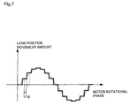
- FIG. 7 is a diagram showing an example of signal output from the LE signal filter 37 in another example of the optical disk apparatus according to the first embodiment
- FIG. 8 is a diagram showing a block configuration of the optical disk apparatus according to a second embodiment
- FIG. 9( a ) is a diagram showing an example of signal output from the LE signal memory regenerator 32 according to a second embodiment, and ( b ) is a diagram showing an example of signal output from an adder 40 according to the second embodiment;
- FIG. 10 is a diagram showing a block configuration of an optical disk apparatus according to a third embodiment
- FIG. 11( a ) is a diagram showing an example of signal output from a light detector 16 according to the third embodiment
- ( b ) is a diagram showing an example of signal output from the LE signal generator 30 according to the third embodiment
- ( c ) is a diagram showing an example of signal output from a TKC generator 52 according to the third embodiment
- ( d ) is a diagram showing an example of an operational state of a selector 51 according to the third embodiment
- ( e ) is a diagram showing another example of an operational state of the selector 51 according to the third embodiment
- FIG. 12 is a diagram showing a block configuration of another example of an optical disk apparatus according to the third embodiment.
- FIG. 13 is a diagram showing a block configuration of another example of an optical disk apparatus according to the third embodiment.
- FIG. 14 is a diagram showing a block configuration of a fourth embodiment
- FIG. 15 is a diagram showing an example of a flowchart showing an entire search according to the fourth embodiment.
- FIG. 16( a ) is a diagram showing a block configuration of an optical disk apparatus described in Background Art
- ( b ) is a diagram showing a configuration of the LE signal filter 37 in the optical disk apparatus described in Background Art;
- FIG. 17( a ) is a diagram showing an example of signal output from the LE signal generator 30 described in Background Art;
- ( b ) is a diagram showing an example of signal output from the LE signal memory regenerator 32 described in Background Art, and
- ( c ) is a diagram showing an example of signal output from the LE signal filter 37 described in Background Art.
- FIG. 1 A block configuration of an optical disk apparatus that is the present first embodiment is shown in FIG. 1 .
- components shown in FIG. 1 which are similar to those shown in FIGS. 16( a ) and ( b ) that represent background art are assigned like reference numerals and descriptions thereof will be omitted.
- a low pass filter 36 is an instrument provided between an LE signal memory regenerator 32 and a subtractor 35 , which cuts off a high-frequency component of an output signal from the LE signal memory regenerator 32 and outputs the same to the subtractor 35 .
- the rotational phase detector 21 corresponds to the rotational phase detection unit according to the present invention and the collecting lens 13 corresponds to the collecting unit according to the present invention.
- the LE signal generator 30 corresponds to the lens position detection unit according to the present invention
- the LE signal memory 33 and the LE signal memory recorder 31 correspond to the lens position storage unit according to the present invention
- the rotational phase shifter 34 and the LE signal memory regenerator 32 correspond to the output unit according to the present invention.
- the subtractor 35 corresponds to the lens position correction unit according to the present invention
- the LE signal filter 37 , the drive circuit 73 and the Tk actuator 15 correspond to the eccentricity correction unit according to the present invention
- the low pass filter 36 corresponds to the high-frequency component reduction unit and the low pass filter according to the present invention.
- the rotational phase detector 21 counts FG signals from the disk motor 20 and generates a rotational phase of the optical disk 1 as a discrete value, and sends the same as rotational phase information to the rotational phase shifter 34 and the LE signal memory recorder 31 .
- the rotational phase shifter 34 sends the same to the LE signal memory regenerator 32 as corrected rotational phase information that has been shifted so as to lag or lead by a predetermined amount.
- the LE signal memory regenerator 32 sends an LE signal whose level corresponds to the rotational phase from the LE signal memory 33 to the low pass filter 36 .
- the low pass filter 36 Upon receiving input of a signal from the LE signal memory regenerator 32 , the low pass filter 36 reduces the high-frequency component and sends the signal to the subtractor 35 .
- the LE signal filter 37 upon receiving a signal from the subtractor 35 , the LE signal filter 37 generates a drive signal whose target value is the stored information of the LE signal memory 33 .
- the drive circuit 73 receives the drive signal and passes a current through the Tk actuator 15 , and moves the Tk actuator 15 in a tracking direction. Consequently, the optical beam operates so as to follow the eccentricity of the optical disk 1 .
- the optical disk apparatus attenuates the high-frequency component of the signal from the LE signal memory regenerator 32 by providing the low pass filter 36 between the LE signal memory regenerator 32 and the subtractor 35 .
- an output signal from the subtractor 35 includes a signal from the LE signal memory regenerator 32 which is given as a discrete value and therefore includes a high-frequency band signal component which is then amplified by differential processing performed by the LE signal filter 37 using a PID filter and incorporated into the drive signal as a drive noise.
- a high-frequency band signal component is attenuated in advance by passing the output from the subtractor 35 through the low pass filter 36 .
- the LE signal shown in FIG. 2( a ) is a continuous quantity
- the signal from the LE signal memory regenerator 32 shown in FIG. 2( b ) is a discrete value. Therefore, an output signal of the subtractor 35 that is the difference of these signals also assumes to have a staircase waveform. This has been a cause of a high-frequency component being amplified as noise during the generation of a drive signal by the LE signal filter 37 .
- the high-frequency band component included in a signal outputted from the subtractor 35 is reduced by passing through the low pass filter 36 in advance. Therefore drive noise amplified by a differential operation of the differential filter 37 c is also reduced. Therefore, as shown in FIG. 2( c ), the signal from the LE signal filter 37 assumes a drive waveform whose noise has been reduced until below a threshold set to the drive circuit 73 .
- the rotational phase shifter 34 is provided in order to accommodate the phase difference, and upon receiving rotational phase information from the rotational phase detector 21 , outputs the rotational phase information advanced by precisely the phase difference P as corrected rotational phase information to the LE signal memory regenerator 32 .
- the LE signal memory generator 32 outputs the signal from the LE signal memory in synchronization with the corrected rotational phase information. While the output signal leads the LE signal shown in FIG. 3( b ) by precisely the phase difference P, the phase difference becomes 0 at the moment of input to the subtractor 35 due to a delay of the low pass filter 36 . In this manner, the rotational phase shifter 34 imparts a phase difference in a direction toward which the inputted rotational phase is advanced in accordance with the delay time at the low pass filter 36 . Accordingly, a signal having passed through the low pass filter 36 is able to maintain proper synchronization.
- the high-frequency band component is removed before the signal passing through the LE signal filter 37 , drive noise during eccentricity correction can be reduced to prevent saturation of the drive circuit 73 and stabilize eccentricity correction operations.
- the present first embodiment is configured so that the low pass filter 36 for reducing a high-frequency band component is provided before the subtractor 35
- the low pass filter 36 may instead be provided between the subtractor 35 and the LE signal filter 37 as is the case with the configuration example shown in FIG. 4 .
- the low pass filter 36 is an example of the high-frequency component reduction unit according to the present invention
- the configuration of the high-frequency component reduction unit according to the present invention is not limited to the configuration described above.
- FIG. 5 is a diagram showing another configuration example of the high-frequency component reduction unit.
- the configuration shown in FIG. 5 is characterized in that a limiter 37 d is provided inside the LE signal filter 37 at a stage subsequent to the differential filter 37 c.
- a signal from the LE signal memory regenerator 32 is subjected to a differential operation at the differential filter 37 c and then passed through the limiter 37 d , thereby limiting at least one of a maximum value and a minimum value of the signal.
- a drive noise appearing in a rising edge portion or a trailing edge portion of the staircase form of the drive signal created after the differential operation is cut off.
- the cut criterion so as to equal or fall below the threshold of the drive circuit 73 , the noise of the drive signal can be kept to or below a certain level.
- the optical disk apparatus is to be configured without the low pass filter 36 shown in FIG. 1 .
- the LE signal filter 37 has been described with reference to FIG. 5 to be configured so that the proportional filter 37 a , the integral filter 37 b and the differential filter 37 c respectively operate in parallel, a configuration in which the integral filter 37 b is serially connected to a subsequent stage of the differential filter 37 c is also possible.
- the limiter 37 d is to be provided between the differential filter 37 c and the integral filter 37 b .
- the limiter 37 d is not restricted by the arrangement of the respective filters in the LE signal filter 37 .
- the limiter 37 d may instead be provided between the LE signal filter 37 and the change-over switch 72 .
- FIG. 6 is a diagram showing another configuration example of the high-frequency component reduction unit.
- FIG. 6 is a diagram showing substantial parts of the optical disk apparatus according to the present embodiment and is a configuration in which a linear interpolator 74 is provided between the subtractor 35 and the LE signal filter 37 .
- the configuration does not include the low pass filter 36 .
- the linear interpolator 74 Upon acquiring corrected rotational phase information from the rotational phase shifter 34 , the linear interpolator 74 multiplies and segmentalizes the information.
- the staircase waveform of the signal outputted from the subtractor 35 is linearly interpolated for each segment of the segmentalized corrected rotational phase information.
- FIG. 7 shows an LE signal in the case where linear interpolation is performed by multiplying by t/10 that is a value equal to 1/10 of a count value t of the FG signal. As shown in FIG.
- smoothing due to linear interpolation to a level where the steps of the staircase waveform are ignorable also smoothes the steps of the signal waveforms of signals subsequent to the computing unit 35 and a drive noise in a rising edge portion or a trailing edge portion is reduced even when differential operation processing is performed by the LE signal filter 37 .
- the multiplication value is not limited to the example shown in FIG. 7 , and any value shall suffice which is capable of shaping the staircase waveform so that the drive noise after the differential operation is reduced to or below the threshold set to the drive circuit 73 .
- the present invention may also be realized as an integrated circuit in which the respective units of the rotational phase detector 21 , the LE signal memory 33 and the LE signal memory recorder 31 , the rotational phase shifter 34 and the LE signal memory regenerator 32 , the subtractor 35 , the LE signal filter 37 , and the low pass filter 36 (or the limiter 37 d or the linear interpolator 74 ) are integrally formed on the same semiconductor substrate and which is provided with the respective functions thereof.
- FIG. 8 A block configuration of an optical disk apparatus that is the present second embodiment is shown in FIG. 8 .
- components shown in FIG. 8 which are similar to those shown in FIG. 16 representing background art are assigned like reference numerals and descriptions thereof will be omitted.
- the optical disk apparatus is provided with a drive signal generation unit 75 comprising a differential filter 39 , an integral proportional filter 38 and an adder 40 .
- the drive signal generation unit 75 While the drive signal generation unit 75 has the same functions as the LE signal filter 37 , the drive signal generation unit 75 inputs an LE signal from the LE signal generator 30 directly to the differential filter 39 , inputs a correction signal from the subtractor 35 directly to the integral proportional filter 38 , and respectively performs a differential operation and an integral operation and a proportional operation at each filter.
- the drive signal generation unit 75 , the drive circuit 73 and the Tk actuator 15 constitute the eccentricity correction unit according to the present invention.
- the differential filter 39 corresponds to the differential filter according to the present invention
- the integral proportional filter 38 corresponds to the integral proportional filter according to the present invention
- the adder 40 corresponds to the adder according to the present invention.
- the second embodiment is characterized in that the drive signal generation unit 75 only inputs an LE signal from the LE signal generator 30 to the differential filter 39 .
- a drive noise in a drive signal is occurred when performing a differential operation on a signal based on a signal from the LE signal memory regenerator 32 which is a discrete quantity and is a signal having a staircase waveform including rising edge portions and trailing edge portions.
- the differential filter 39 performs a differential operation on an LE signal from the LE signal generator 30 as described above
- the LE signal is a continuous quantity having a smooth waveform and does not include a high-frequency component. Therefore, distortions of the rising edge portions and trailing edge portions do not occur even when a differential operation is performed.
- an output signal from the subtractor 35 includes a signal from the LE signal memory regenerator 32 which is given as a discrete value and therefore includes a high-frequency band signal component and assumes a staircase waveform, since an integral operation and a proportional operation do not influence the high-frequency band signal component, no distortion occurs in the shape of the output signal from the integral proportional filter 38 .
- a distortion-suppressed waveform can be obtained as a drive signal from the adder 40 shown in FIG. 9( b ).
- the optical disk apparatus of the present embodiment by providing a configuration in which a differential operation is not performed on a signal based on the LE signal memory regenerator 32 , the drive noise of eccentricity correction can be reduced.
- the present invention may also be realized as an integrated circuit in which the respective units of the rotational phase detector 21 , the LE signal memory 33 and the LE signal memory recorder 31 , the rotational phase shifter 34 and the LE signal memory regenerator 32 , the subtractor 35 and the drive signal generation unit 75 are integrally formed on the same semiconductor substrate and which is provided with the respective functions thereof.
- An optical disk apparatus enables lens control to be performed in a stable manner even when a movement speed of the optical head in a tracking direction decreases. A description will now be given with reference to FIG. 10 .
- FIG. 10 A block configuration of an optical disk apparatus that is the present third embodiment is shown in FIG. 10 .
- components shown in FIG. 10 which are similar to those shown in FIG. 16 representing background art are assigned like reference numerals and descriptions thereof will be omitted.
- a motor 80 is an instrument which moves the optical head 10 in a tracking direction of the optical disk 1 along a shaft 81 .
- a TKC generator 52 is an instrument which generates, based on a light reception signal of the light detector 16 , a TKC (track cross) signal occurring when an optical beam from the collecting lens 13 crosses tracks of the optical disk 1
- a lens speed detector 50 is an instrument which detects a speed of the collecting lens 13 based on the TKC signal
- the selector 51 is an instrument which selects whether an output signal from the LE signal filter 37 is to be outputted to the drive circuit 73 side based on a detection result of the lens speed detector 50 .
- the motor 80 and the shaft 81 are known technical instruments and, needless to say, are provided even if not explicitly shown in the background art shown in FIG. 16 or in the other embodiments.
- the TKC generator 52 and the lens speed detector 50 correspond to the lens speed detection unit according to the present invention and the selector 51 corresponds to the eccentricity correction operation suspension unit according to the present invention.
- the TKC generator 52 corresponds to the track cross detection unit according to the present invention.
- the TKC generator 52 detects an optical beam having passed an edge of a track of the optical disk 1 by using a signal from the light detector 16 , generates a TKC signal having an edge of a binarization signal and sends the generated signal to the lens speed detector 50 .
- the lens speed detector 50 measures a cycle of the TKC signal from the TKC generator 52 , and detects a lens speed based thereon and sends the detected speed to the selector 51 .
- a value having a predetermined level to become a criterion of judging operations is set.
- a binary judgment is performed where the lens speed is compared to a set speed value.
- a direct current having a voltage value of 0 is sent to the Tk actuator 15 as a drive current. Consequently, since the drive signal from the LE signal filter 37 is blocked and the drive signal will be held at DC level 0 , the Tk actuator 15 is not activated.
- the lens speed from the lens speed detector 50 is greater than a value of a predetermined level, the drive signal from the LE signal filter 37 is sent without modification to the Tk actuator 15 .
- lens control based on a LE signal is executed only when the lens speed is greater than a predetermined level. As a result, the following advantage is achieved.
- FIGS. 11( a ) to ( d ) are diagrams showing an example of a change in signal output from respective units of an optical disk apparatus according to the present embodiment on the same temporal axis.
- FIG. 11( a ) shows an output of a signal from the light detector 16
- FIG. 11( b ) shows an output of a signal from the LE signal generator 30
- FIG. 11( c ) shows an output of a signal from the TKC generator 52
- FIG. 6( a ) shows a connection state of the selector 51 .
- the signal from the light detector 16 has a sinusoidal waveform in accordance to the crossing speed.
- the signal of the LE signal generator 30 assumes to have a waveform such as that shown in FIG. 11( b ) due to the top hold push-pull method.
- the signal from the TKC generator 52 has a waveform such as that shown in FIG. 11( c ), and an edge appears as a result of the crossing of the optical beam with respect to tracks of the optical disk 1 .
- the lens speed detector 50 detects a crossing speed of the optical beam with respect to tracks of the optical disk 1 by measuring the time between edges of FIG. 11( c ), and when the crossing speed is equal to or lower than a predetermined level, blocks the signal from the LE signal filter 37 .
- the accuracy of an LE signal obtained from the LE signal generator 30 using the top hold push-pull method is dependent on the movement speed of the optical beam in a tracking direction, and is likely to include errors when the speed is low. Therefore, lens control based on an LE signal including such errors deteriorates following accuracy and prevents stable operations.
- following accuracy is increased by suspending lens control when the movement speed of the optical beam in a tracking direction is low.
- period (1) is a period in which the optical beam departs from a predetermined track and starts moving towards a target track
- the accuracy of eccentricity correction is not considered particularly important.
- period (3) after arriving on the target track, since the optical beam is placed under tracking control using a TE signal which is more accurate than lens control, an eccentricity correction operation is accomplished without having to rely on lens control.
- lens wobbling can be reduced by suspending lens control using an LE signal.
- the configuration of the lens speed detection unit according to the present invention is not limited thereto.
- FIG. 12 is a diagram showing another configuration example of an optical disk apparatus according to the present third embodiment.
- the TKC generator 52 has been eliminated and the lens speed detector 50 is arranged to acquire a drive current of the motor 80 which moves the optical head 10 and, based thereon, detect a movement speed of the optical head 10 as a speed of the collecting lens 13 .
- the lens speed detector 50 may be arranged as a speed sensor to directly detect the movement speed of the optical head 10 .
- the lens speed detector 50 corresponds to the optical head speed detection unit according to the present invention.
- FIG. 13 is a diagram showing yet another configuration example of an optical disk apparatus according to the present third embodiment.
- the lens speed detector 50 is arranged to acquire an optical head movement target profile that is a parameter for determining a movement target speed of the optical head from a speed control unit 82 for driving the motor 80 , which moves the optical head 10 , at a predetermined speed, and based thereon, detects a movement speed of the optical head 10 as a speed of the collecting lens 13 .
- the speed control unit 82 corresponds to the optical head movement target retention unit according to the present invention.
- the lens speed detection unit may be arranged to estimate a movement speed in a tracking direction of the collecting lens 13 as a movement of the optical head 10 or to directly measure the movement speed from a movement of the collecting lens 13 itself, and is not limited to a specific configuration thereof.
- the Tk actuator 15 is arranged to be held at DC level 0 when lens control is not performed, the Tk actuator 15 may be held at an arbitrary voltage value.
- the present invention may also be realized as an integrated circuit in which the respective units of the rotational phase detector 21 , the LE signal memory 33 and the LE signal memory recorder 31 , the LE signal memory regenerator 32 , the subtractor 35 , the TKC generator 52 (or the speed control unit 82 ), the lens speed detector 50 and the selector 51 are integrally formed on the same semiconductor substrate and which is provided with the respective functions thereof.
- FIG. 14 A block configuration of an optical disk apparatus that is the present fourth embodiment is shown in FIG. 14 . It should be noted that components shown in FIG. 14 similar to those shown in FIGS. 16 , 1 and 10 representing background art and the present first and third embodiments are assigned like reference numerals, and descriptions on operations similar to these embodiments will be omitted.
- the LE signal filter 37 is an instrument which generates a drive signal which drives the Tk actuator 15 so that the lens position follows the optical head 10 to keep at a predetermined position.
- a TK signal filter 71 is an instrument which generates a drive signal which drives the Tk actuator 15 so that an optical beam follows a track of the optical disk 1 .
- a movement drive generator 68 is an instrument which generates a drive signal for moving the optical head 10 during a search.
- a lens control disable command 66 is a command which disables the drive signal from the LE signal filter 37 and causes zero to be generated after the command.
- a lens control enable command 64 is a command which enables the drive signal from the LE signal filter 37 after the command.
- a tracking control disable command 63 is a command which disables the drive signal from the TK signal filter 71 and causes zero to be generated after the command.
- a tracking control enable command 65 is a command which enables the drive signal from the TK signal filter 71 after the command.
- a head move command 60 is a command which causes the movement drive generator 68 to generate a drive signal for moving the optical head 10 in a radial direction of the optical disk 1 by a specified amount.
- a parameter set command 61 is a command for setting internal parameters of the LE signal filter 37 , the TK signal filter 71 and the movement drive generator 68 .
- a search instruction unit 62 is an instrument which causes a search operation to be executed according to a flowchart shown in FIG. 15 .
- the tracking control disable command 63 and the lens control enable command 64 correspond to a lens control switching command of the invention made by the present inventors to be described later.
- the head move command 60 corresponds to the move command.
- the tracking control enable command 65 and the lens control disable command 66 correspond to the tracking control switching command.
- the parameter set command 61 corresponds to the parameter set command.
- the search instruction unit 62 corresponds to the search instruction unit.
- the tracking control enable command 65 corresponds to the tracking control enable command.
- the tracking control disable command 63 corresponds to the tracking control disable command.
- the lens control enable command 64 corresponds to the lens control enable command.
- the lens control disable command 66 corresponds to the lens control disable command.
- Step S 101 Execute the tracking control disable command 63 specifying that DC drive be retained.
- Step S 102 Set gain of LE signal filter 37 using parameter set command 61 .
- Step S 103 Execute lens control enable command 64 .
- Step S 104 Set target profile of movement drive generator 68 using parameter set command 61 .
- Step S 105 Execute head move command 60 and move optical head 10 to a predetermined position.
- Step S 106 Set gain of LE signal filter 37 using parameter set command 61 .
- Step S 107 Execute the lens control disable command 66 specifying that DC drive be retained.
- Step S 108 Set gain of TK signal filter 71 using parameter set command 61 .
- Step S 109 Execute tracking control enable command 65 .
- the LE signal filter 37 , the TK signal filter 71 , the movement drive generator 68 , the tracking control enable command 65 , the tracking control disable command 63 , the lens control enable command 64 , the lens control disable command 66 , the head move command 60 and the parameter set command 61 are executed by unrewritable software or hardware in a semiconductor for an optical disk apparatus as an integrated circuit according to the present invention.
- the search instruction unit 62 is configured in a rewritable external CPU.
- the search instruction unit 62 which issues instructions for executing commands such as described above separates commands according to each control operation and realizes a search operation by having the external CPU sequentially issue instructions.
- parameters such as a gain and the like can be set between the respective commands.
- parameters such as the focus control gain when moving the optical head 10 during a search can be liberally changed from the CPU using a simple configuration without causing performance deterioration.
- the contents of parameter settings shown in FIG. 14 are merely examples and arbitrary parameters may be set.
- the parameters may be used for the optical disk apparatuses according to the first and second embodiments or for controlling a conventional optical disk apparatus.
- the present fourth embodiment may take the form of a search instruction unit of an optical disk apparatus comprising unrewritable software or hardware, the search instruction unit capable of issuing a lens control switching command which, in response to an instruction from an external CPU core, disables control which causes an optical beam to follow a track of an information carrier, and enables control which causes the optical beam to assume a predetermined position with respect to an optical head; a move command which, in response to an instruction from the external CPU core, moves the optical head; a tracking control switching command which, in response to an instruction from the external CPU core, enables control which causes the optical beam to follow a track of an information carrier, and disables control which causes the optical beam to assume a predetermined position with respect to the optical head; and a parameter set command which, in response to an instruction from the external CPU core, is capable of setting a value to an arbitrary RAM, wherein the search instruction unit outputs the lens control switching command, the parameter set command, the move command, the parameter set command and the tracking control switching command in this order.
- the respective configurations of the first to fourth embodiments may be implemented in combination thereof. More specifically, the configuration according to the first and second embodiments which performs processing of the high-frequency component of an LE signal, the configuration according to the third embodiment which controls the execution of lens control based on the movement speed of an optical beam in a tracking direction, and the configuration according to the fourth embodiment in which control of the respective commands is executed by the search instruction unit may be implemented in the same optical disk apparatus.
- the program according to the present invention is a program for causing a computer to execute all of or a part of the functions constituting the above-described optical disk apparatus according to the present invention, and may be a program which operates in cooperation with a computer.
- the present invention may be a storage medium storing a program for causing a computer to execute all of or a part of functions of all of or a part of instruments constituting the above-described optical disk apparatus according to the present invention which is computer readable and in which the read program cooperates with the computer to execute the functions.
- a part of instruments described above according to the present invention may either represent some of the instruments among the plurality of instruments thereof or a part of functions in an instrument.
- a computer-readable storage medium storing the program according to the present invention is also included in the present invention.
- the program may be stored on a computer-readable storage medium and operated in cooperation with the computer.
- the program may be transmitted through a transmission medium and read by a computer, and operated in cooperation with the computer.
- storage media include a ROM and the like.
- a computer according to the present invention described above is not limited to pure hardware such as a CPU and may be arranged to include firmware, an OS and, furthermore, peripheral devices.
- configurations of the present invention may either be realized through software or through hardware.
- An optical disk apparatus, a control method of the optical disk apparatus and an integrated circuit according to the present invention achieves an advantage that eccentricity correction operations can be performed stably, and are useful as an optical disk apparatus, a control method of the optical disk, an integrated circuit and the like.
Landscapes
- Optical Recording Or Reproduction (AREA)
Abstract
Description
-
- a rotary drive unit which rotationally drives an information carrier;
- a rotational phase detection unit which detects a rotational phase of the information carrier;
- an optical head having a collecting unit which collects an optical beam on the information carrier;
- a lens position detection unit which detects a position of the collecting unit in the optical head as a position signal;
- a lens position storage unit which stores, in synchronization with a rotational phase to be detected by the rotational phase detection unit, the positional signal from the lens position detection unit corresponding to the rotational phase to be detected;
- an output unit which outputs as a correction signal, in synchronization with a rotational phase to be detected by the rotational phase detection unit, the positional signal stored by the lens position storage unit and which has already been detected by the lens position detection unit;
- a lens position correction unit which corrects the position signal detected by the lens position detection unit using the correction signal;
- an eccentricity correction unit which generates a drive signal using a signal from the lens position correction unit and, based thereon, moves the collecting unit in a radial direction of the information carrier; and
- a high-frequency component reduction unit which reduces a high-frequency component of any of the correction signal, an output signal of the lens position correction unit and the drive signal.
-
- a rotary drive unit which rotationally drives an information carrier;
- a rotational phase detection unit which detects a rotational phase of the information carrier;
- an optical head having a collecting unit which collects an optical beam on the information carrier;
- a lens position detection unit which detects a position of the collecting unit in the optical head as a position signal;
- a lens position storage unit which stores, in synchronization with a rotational phase to be detected by the rotational phase detection unit, the positional signal from the lens position detection unit corresponding to the rotational phase to be detected;
- an output unit which outputs as a correction signal, in synchronization with a rotational phase to be detected by the rotational phase detection unit, the positional signal stored by the lens position storage unit and which has already been detected by the lens position detection unit;
- a lens position correction unit which corrects the position signal detected by the lens position detection unit using the correction signal; and
- an eccentricity correction unit which generates a drive signal using a signal from the lens position correction unit and, based thereon, moves the collecting unit in a radial direction of the information carrier, wherein
- the eccentricity correction unit generates the drive signal without performing a differential operation on a signal outputted from the lens position correction unit.
-
- the eccentricity correction unit includes:
- a differential filter which performs a differential operation on the position signal;
- an integral proportional filter which performs at least one of a proportional operation and an integral operation on a signal outputted from the lens position correction unit; and
- an adder which adds the outputs of the differential filter and the integral proportional filter.
-
- a rotary drive unit which rotationally drives an information carrier;
- a rotational phase detection unit which detects a rotational phase of the information carrier;
- an optical head having a collecting unit which collects an optical beam on the information carrier;
- a lens position detection unit which detects a position of the collecting unit in the optical head as a position signal;
- a lens position storage unit which stores, in synchronization with a rotational phase to be detected by the rotational phase detection unit, the positional signal from the lens position detection unit corresponding to the rotational phase to be detected;
- an output unit which outputs as a correction signal, in synchronization with a rotational phase to be detected by the rotational phase detection unit, the positional signal stored by the lens position storage unit and which has already been detected by the lens position detection unit;
- a lens position correction unit which corrects the position signal detected by the lens position detection unit using the correction signal;
- an eccentricity correction unit which moves the collecting unit in a radial direction of the information carrier based on a signal from the lens position correction unit;
- a lens speed detection unit which detects a speed of the collecting unit; and
- an eccentricity correction operation suspension unit which suspends an operation of the eccentricity correction unit when speed information from the lens speed detection unit is equal to or lower than a predetermined level.
-
- the lens speed detection unit includes a track cross detection which detects an optical beam having crossed the tracks of the information carrier and outputs the result of detection as an edge of a binarization signal, and
- the lens speed detection unit detects a speed of the collecting unit by measuring a cycle of a signal from the track cross detection unit.
-
- the lens speed detection unit includes an optical head movement target retention unit which retains an optical head movement target speed profile during a search of a track of the information carrier, and
- the lens speed detection unit estimates a movement speed of the optical head based on a signal from the optical head movement target retention unit.
-
- a tracking error signal detection unit which detects a reflected signal from a recording track of the optical disk as a tracking error signal; and
- a tracking control unit which moves the collecting unit in a radial direction of the information carrier based on the tracking error signal, wherein
- the tracking control unit holds a DC level of a drive signal for moving the collecting unit when not performing the operation.
-
- a step for rotationally driving an information carrier;
- a step for detecting a rotational phase of the information carrier;
- a step for detecting, in an optical head having a collecting unit which collects an optical beam on the information carrier, a position of the collecting unit as a position signal;
- a step for storing, in synchronization with a detected rotational phase, the positional signal from the lens position detection unit corresponding to the rotational phase to be detected;
- a step for outputting, in synchronization with a detected rotational phase, the stored and already detected positional signal as a correction signal;
- a step for correcting the detected position signal using the correction signal; and
- a step for generating a drive signal using the corrected position signal and, based thereon, moving the collecting unit in a radial direction of the information carrier, wherein the control method includes:
- a step for reducing a high-frequency component of any of the correction signal, an output signal of the lens position correction unit and the drive signal.
-
- a step for rotationally driving an information carrier;
- a step for detecting a rotational phase of the information carrier;
- a step for detecting, in an optical head having a collecting unit which collects an optical beam on the information carrier, a position of the collecting unit as a position signal;
- a step for storing, in synchronization with a detected rotational phase, the positional signal from the lens position detection unit corresponding to the rotational phase to be detected;
- a step for outputting, in synchronization with a detected rotational phase, the stored and already detected positional signal as a correction signal;
- a step for correcting the detected position signal using the correction signal; and
- a step for generating a drive signal using the corrected position signal and, based thereon, moving the collecting unit in a radial direction of the information carrier, wherein
- the control method generates the drive signal without performing a differential operation on the corrected position signal.
-
- a step for rotationally driving an information carrier;
- a step for detecting a rotational phase of the information carrier;
- a step for detecting, in an optical head having a collecting unit which collects an optical beam on the information carrier, a position of the collecting unit as a position signal;
- a step for storing, in synchronization with a detected rotational phase, the positional signal from the lens position detection unit corresponding to the rotational phase to be detected;
- a step for outputting, in synchronization with a detected rotational phase, the stored and already detected positional signal as a correction signal;
- a step for correcting the detected position signal using the correction signal;
- a step for generating a drive signal using the corrected position signal and, based thereon, moving the collecting unit in a radial direction of the information carrier;
- a step for detecting a speed of the collecting unit; and
- a step for suspending an operation of the eccentricity correction unit when the detected speed information is equal to or lower than a predetermined level.
- 1 Optical disk
- 10 Optical head
- 11 Semiconductor laser
- 12 Beam splitter
- 13 Collecting lens
- 14 Fc actuator
- 15 Tk actuator
- 16 Light detector
- 20 Disk motor
- 21 Rotational phase detector
- 30 LE signal generator
- 31 LE signal memory recorder
- 32 LE signal memory regenerator
- 33 LE signal memory
- 34 Rotational phase shifter
- 35 Subtractor
- 36 Low pass filter
- 37 LE signal filter
- 37 a Proportional filter
- 37 b Integral filter
- 37 c Differential filter
- 37 d Limiter
- 38 Integral proportional filter
- 39 Differential filter
- 40 Adder
- 50 Lens speed detector
- 51 Selector
- 52 TKC generator
- 60 Head move command
- 61 Parameter set command
- 62 Search instruction unit
- 63 Tracking control disable command
- 64 Lens control enable command
- 65 Tracking control enable command
- 66 Lens control disable command
- 68 Movement drive generator
- 70 TK signal generator
- 71 TK signal filter
- 72 Change-over switch
- 73 Drive circuit
- 74 Linear interpolator
- 75 Drive signal generation unit
- 80 Motor
- 80 Shaft
- 82 Speed control unit
Claims (26)
Applications Claiming Priority (3)
| Application Number | Priority Date | Filing Date | Title |
|---|---|---|---|
| JP2006-019503 | 2006-01-27 | ||
| JP2006019503 | 2006-01-27 | ||
| PCT/JP2007/051204 WO2007086482A1 (en) | 2006-01-27 | 2007-01-25 | Optical disc device, optical disc device control method, and integrated circuit |
Publications (2)
| Publication Number | Publication Date |
|---|---|
| US20090010126A1 US20090010126A1 (en) | 2009-01-08 |
| US8072858B2 true US8072858B2 (en) | 2011-12-06 |
Family
ID=38309271
Family Applications (1)
| Application Number | Title | Priority Date | Filing Date |
|---|---|---|---|
| US12/162,196 Expired - Fee Related US8072858B2 (en) | 2006-01-27 | 2007-01-25 | Optical disk apparatus, control method of optical disk apparatus, and integrated circuit |
Country Status (4)
| Country | Link |
|---|---|
| US (1) | US8072858B2 (en) |
| JP (1) | JP4999708B2 (en) |
| CN (1) | CN101375331B (en) |
| WO (1) | WO2007086482A1 (en) |
Cited By (1)
| Publication number | Priority date | Publication date | Assignee | Title |
|---|---|---|---|---|
| US20130159612A1 (en) * | 2010-03-19 | 2013-06-20 | Netlogic Microsystems, Inc. | Programmable Drive Strength in Memory Signaling |
Families Citing this family (1)
| Publication number | Priority date | Publication date | Assignee | Title |
|---|---|---|---|---|
| JP6753262B2 (en) * | 2016-10-14 | 2020-09-09 | オムロン株式会社 | Control and communication equipment |
Citations (13)
| Publication number | Priority date | Publication date | Assignee | Title |
|---|---|---|---|---|
| JPH02272030A (en) | 1989-04-14 | 1990-11-06 | Ube Ind Ltd | Improvement in fluidity of powdery polyethylene |
| JPH02292738A (en) | 1989-05-02 | 1990-12-04 | Canon Inc | Optical disk driving device |
| JPH03272030A (en) | 1990-03-20 | 1991-12-03 | Nec Home Electron Ltd | Disk reproducing device |
| JPH05135390A (en) | 1991-11-15 | 1993-06-01 | Matsushita Electric Ind Co Ltd | Optical head controller |
| JPH08180426A (en) | 1994-12-27 | 1996-07-12 | Matsushita Electric Ind Co Ltd | Disk device tracking controller |
| JPH09274726A (en) | 1996-04-04 | 1997-10-21 | Sony Corp | Optical pickup device |
| JP2000086283A (en) | 1998-09-08 | 2000-03-28 | Ohara Inc | Luminescent glass |
| JP2001160226A (en) | 1999-09-20 | 2001-06-12 | Matsushita Electric Ind Co Ltd | Optical disk drive |
| US6370094B1 (en) * | 1997-08-05 | 2002-04-09 | Fujitsu Limited | Optical storage apparatus |
| US6498772B1 (en) | 1999-09-20 | 2002-12-24 | Matsushita Electric Industrial Co., Ltd. | Optical disc apparatus |
| JP2005182968A (en) | 2003-12-24 | 2005-07-07 | Hitachi Ltd | Optical disc apparatus and eccentricity correction method thereof |
| US7257052B2 (en) * | 2002-02-05 | 2007-08-14 | Matsushita Electric Industrial Co., Ltd. | Control apparatus and optical disk apparatus |
| US7782724B2 (en) * | 2005-01-18 | 2010-08-24 | Fujitsu Limited | Information reproducing apparatus and method for measuring surface deflection |
-
2007
- 2007-01-25 US US12/162,196 patent/US8072858B2/en not_active Expired - Fee Related
- 2007-01-25 JP JP2007556004A patent/JP4999708B2/en not_active Expired - Fee Related
- 2007-01-25 WO PCT/JP2007/051204 patent/WO2007086482A1/en not_active Ceased
- 2007-01-25 CN CN2007800036001A patent/CN101375331B/en not_active Expired - Fee Related
Patent Citations (14)
| Publication number | Priority date | Publication date | Assignee | Title |
|---|---|---|---|---|
| JPH02272030A (en) | 1989-04-14 | 1990-11-06 | Ube Ind Ltd | Improvement in fluidity of powdery polyethylene |
| JPH02292738A (en) | 1989-05-02 | 1990-12-04 | Canon Inc | Optical disk driving device |
| JPH03272030A (en) | 1990-03-20 | 1991-12-03 | Nec Home Electron Ltd | Disk reproducing device |
| JPH05135390A (en) | 1991-11-15 | 1993-06-01 | Matsushita Electric Ind Co Ltd | Optical head controller |
| JPH08180426A (en) | 1994-12-27 | 1996-07-12 | Matsushita Electric Ind Co Ltd | Disk device tracking controller |
| JPH09274726A (en) | 1996-04-04 | 1997-10-21 | Sony Corp | Optical pickup device |
| US6370094B1 (en) * | 1997-08-05 | 2002-04-09 | Fujitsu Limited | Optical storage apparatus |
| US6300264B1 (en) | 1998-09-08 | 2001-10-09 | Kabushiki Kaisha Ohara | Luminous glass |
| JP2000086283A (en) | 1998-09-08 | 2000-03-28 | Ohara Inc | Luminescent glass |
| JP2001160226A (en) | 1999-09-20 | 2001-06-12 | Matsushita Electric Ind Co Ltd | Optical disk drive |
| US6498772B1 (en) | 1999-09-20 | 2002-12-24 | Matsushita Electric Industrial Co., Ltd. | Optical disc apparatus |
| US7257052B2 (en) * | 2002-02-05 | 2007-08-14 | Matsushita Electric Industrial Co., Ltd. | Control apparatus and optical disk apparatus |
| JP2005182968A (en) | 2003-12-24 | 2005-07-07 | Hitachi Ltd | Optical disc apparatus and eccentricity correction method thereof |
| US7782724B2 (en) * | 2005-01-18 | 2010-08-24 | Fujitsu Limited | Information reproducing apparatus and method for measuring surface deflection |
Non-Patent Citations (1)
| Title |
|---|
| International Search Report for PCT/JP2007/051204, dated May 15, 2007. |
Cited By (2)
| Publication number | Priority date | Publication date | Assignee | Title |
|---|---|---|---|---|
| US20130159612A1 (en) * | 2010-03-19 | 2013-06-20 | Netlogic Microsystems, Inc. | Programmable Drive Strength in Memory Signaling |
| US8700944B2 (en) * | 2010-03-19 | 2014-04-15 | Netlogic Microsystems, Inc. | Programmable drive strength in memory signaling |
Also Published As
| Publication number | Publication date |
|---|---|
| CN101375331A (en) | 2009-02-25 |
| CN101375331B (en) | 2011-09-28 |
| US20090010126A1 (en) | 2009-01-08 |
| WO2007086482A1 (en) | 2007-08-02 |
| JPWO2007086482A1 (en) | 2009-06-25 |
| JP4999708B2 (en) | 2012-08-15 |
Similar Documents
| Publication | Publication Date | Title |
|---|---|---|
| JP3968984B2 (en) | Optical disc playback apparatus and disc type discrimination method | |
| JPH06282849A (en) | Optical recording medium, recording / reproducing apparatus for optical recording medium, and reproducing apparatus | |
| US8305855B2 (en) | Information processing apparatus and information processing method | |
| US20070280066A1 (en) | Apparatus for controling servo signal gains of an optical disc drive and method of same | |
| US8072858B2 (en) | Optical disk apparatus, control method of optical disk apparatus, and integrated circuit | |
| US7315491B2 (en) | Disk driving apparatus and information readout method with selective servo control for read-out destinations of lands and grooves | |
| JP2003346369A (en) | Optical recording / reproducing apparatus and tilt control method | |
| US7366065B2 (en) | Optical disk apparatus and an optical disk recording and reproducing method | |
| US7719931B2 (en) | Optical disk device, loop gain setting method, and loop gain setting program | |
| KR20050030168A (en) | Defect detection device and defect detection method | |
| JP2931042B2 (en) | Optical disc playback device | |
| US7738328B2 (en) | Optical disk apparatus for carrying out a defocus regulation | |
| US8559285B2 (en) | Optical disc apparatus | |
| JP2007172810A (en) | Optical disc apparatus and optical-pickup movement control method used in the same | |
| US7660220B2 (en) | Optical disc drive apparatus and signal recording method | |
| JP4896228B2 (en) | Optical disc recording apparatus and method, and computer program | |
| JP2010113750A (en) | Optical disk device | |
| JP4951577B2 (en) | Disc playback apparatus and disc playback method | |
| US20090196130A1 (en) | Information recording/reproducing apparatus | |
| US20100149935A1 (en) | Optical Disc Device | |
| JP4968753B2 (en) | Information recording / reproducing apparatus and method | |
| JP2008047202A (en) | Optical disc reproducing apparatus, servo control apparatus, and servo control signal generation method | |
| JP2008524767A (en) | Optical focus error offset to suppress radial-vertical crosstalk | |
| JP2008524760A (en) | How to measure and optimize radial vertical crosstalk | |
| JPH11195226A (en) | Optical disk drive device and tracking servo control method |
Legal Events
| Date | Code | Title | Description |
|---|---|---|---|
| AS | Assignment |
Owner name: PANASONIC CORPORATION, JAPAN Free format text: ASSIGNMENT OF ASSIGNORS INTEREST;ASSIGNORS:FUJIUNE, KENJI;KIKUCHI, JUN;REEL/FRAME:021635/0945 Effective date: 20080717 |
|
| AS | Assignment |
Owner name: PANASONIC CORPORATION, JAPAN Free format text: CHANGE OF NAME;ASSIGNOR:MATSUSHITA ELECTRIC INDUSTRIAL CO., LTD.;REEL/FRAME:021779/0851 Effective date: 20081001 Owner name: PANASONIC CORPORATION,JAPAN Free format text: CHANGE OF NAME;ASSIGNOR:MATSUSHITA ELECTRIC INDUSTRIAL CO., LTD.;REEL/FRAME:021779/0851 Effective date: 20081001 |
|
| STCF | Information on status: patent grant |
Free format text: PATENTED CASE |
|
| FPAY | Fee payment |
Year of fee payment: 4 |
|
| FEPP | Fee payment procedure |
Free format text: MAINTENANCE FEE REMINDER MAILED (ORIGINAL EVENT CODE: REM.); ENTITY STATUS OF PATENT OWNER: LARGE ENTITY |
|
| LAPS | Lapse for failure to pay maintenance fees |
Free format text: PATENT EXPIRED FOR FAILURE TO PAY MAINTENANCE FEES (ORIGINAL EVENT CODE: EXP.); ENTITY STATUS OF PATENT OWNER: LARGE ENTITY |
|
| STCH | Information on status: patent discontinuation |
Free format text: PATENT EXPIRED DUE TO NONPAYMENT OF MAINTENANCE FEES UNDER 37 CFR 1.362 |
|
| FP | Expired due to failure to pay maintenance fee |
Effective date: 20191206 |