US8072516B2 - Dynamic range enhancement method and apparatus - Google Patents
Dynamic range enhancement method and apparatus Download PDFInfo
- Publication number
- US8072516B2 US8072516B2 US12/315,028 US31502808A US8072516B2 US 8072516 B2 US8072516 B2 US 8072516B2 US 31502808 A US31502808 A US 31502808A US 8072516 B2 US8072516 B2 US 8072516B2
- Authority
- US
- United States
- Prior art keywords
- dynamic range
- image
- var
- gamma corrected
- gamma
- Prior art date
- Legal status (The legal status is an assumption and is not a legal conclusion. Google has not performed a legal analysis and makes no representation as to the accuracy of the status listed.)
- Expired - Fee Related, expires
Links
Images


Classifications
-
- H—ELECTRICITY
- H04—ELECTRIC COMMUNICATION TECHNIQUE
- H04N—PICTORIAL COMMUNICATION, e.g. TELEVISION
- H04N5/00—Details of television systems
- H04N5/44—Receiver circuitry for the reception of television signals according to analogue transmission standards
- H04N5/57—Control of contrast or brightness
-
- H—ELECTRICITY
- H04—ELECTRIC COMMUNICATION TECHNIQUE
- H04N—PICTORIAL COMMUNICATION, e.g. TELEVISION
- H04N21/00—Selective content distribution, e.g. interactive television or video on demand [VOD]
- H04N21/40—Client devices specifically adapted for the reception of or interaction with content, e.g. set-top-box [STB]; Operations thereof
- H04N21/41—Structure of client; Structure of client peripherals
- H04N21/414—Specialised client platforms, e.g. receiver in car or embedded in a mobile appliance
- H04N21/41407—Specialised client platforms, e.g. receiver in car or embedded in a mobile appliance embedded in a portable device, e.g. video client on a mobile phone, PDA, laptop
-
- H—ELECTRICITY
- H04—ELECTRIC COMMUNICATION TECHNIQUE
- H04N—PICTORIAL COMMUNICATION, e.g. TELEVISION
- H04N21/00—Selective content distribution, e.g. interactive television or video on demand [VOD]
- H04N21/40—Client devices specifically adapted for the reception of or interaction with content, e.g. set-top-box [STB]; Operations thereof
- H04N21/41—Structure of client; Structure of client peripherals
- H04N21/422—Input-only peripherals, i.e. input devices connected to specially adapted client devices, e.g. global positioning system [GPS]
- H04N21/4223—Cameras
-
- H—ELECTRICITY
- H04—ELECTRIC COMMUNICATION TECHNIQUE
- H04N—PICTORIAL COMMUNICATION, e.g. TELEVISION
- H04N21/00—Selective content distribution, e.g. interactive television or video on demand [VOD]
- H04N21/40—Client devices specifically adapted for the reception of or interaction with content, e.g. set-top-box [STB]; Operations thereof
- H04N21/43—Processing of content or additional data, e.g. demultiplexing additional data from a digital video stream; Elementary client operations, e.g. monitoring of home network or synchronising decoder's clock; Client middleware
- H04N21/431—Generation of visual interfaces for content selection or interaction; Content or additional data rendering
- H04N21/4318—Generation of visual interfaces for content selection or interaction; Content or additional data rendering by altering the content in the rendering process, e.g. blanking, blurring or masking an image region
-
- H—ELECTRICITY
- H04—ELECTRIC COMMUNICATION TECHNIQUE
- H04N—PICTORIAL COMMUNICATION, e.g. TELEVISION
- H04N23/00—Cameras or camera modules comprising electronic image sensors; Control thereof
- H04N23/10—Cameras or camera modules comprising electronic image sensors; Control thereof for generating image signals from different wavelengths
- H04N23/11—Cameras or camera modules comprising electronic image sensors; Control thereof for generating image signals from different wavelengths for generating image signals from visible and infrared light wavelengths
-
- H—ELECTRICITY
- H04—ELECTRIC COMMUNICATION TECHNIQUE
- H04N—PICTORIAL COMMUNICATION, e.g. TELEVISION
- H04N23/00—Cameras or camera modules comprising electronic image sensors; Control thereof
- H04N23/70—Circuitry for compensating brightness variation in the scene
- H04N23/741—Circuitry for compensating brightness variation in the scene by increasing the dynamic range of the image compared to the dynamic range of the electronic image sensors
-
- H—ELECTRICITY
- H04—ELECTRIC COMMUNICATION TECHNIQUE
- H04N—PICTORIAL COMMUNICATION, e.g. TELEVISION
- H04N23/00—Cameras or camera modules comprising electronic image sensors; Control thereof
- H04N23/80—Camera processing pipelines; Components thereof
- H04N23/82—Camera processing pipelines; Components thereof for controlling camera response irrespective of the scene brightness, e.g. gamma correction
- H04N23/83—Camera processing pipelines; Components thereof for controlling camera response irrespective of the scene brightness, e.g. gamma correction specially adapted for colour signals
Definitions
- the present invention relates to an imaging device and a dynamic range enhancement method and apparatus therefore to improve image quality.
- An image sensor is a device that converts an optical image to an electric signal.
- an image sensor comprises a Charge-Coupled Device (CCD) or a Complementary Metal-Oxide-Silicon (CMOS) sensor.
- CCD image sensor typically serializes parallel analog signals, which are in arrays of photoelectric light sensors by capacitors transferring an electric charge of each pixel to a common output structure which converts the charge to a voltage and buffers and sends the voltage off-chip.
- pixels represented by respective MOS transistors convert the charges to voltages and the voltages are output in accordance with switching operations of the transistors.
- Dynamic range is a ratio of a pixel's saturation level to its signal threshold.
- the dynamic range refers to the maximum signal power that the device can tolerate without distortion of the input signal.
- the ability to measure the dimmest intensities in an image is improved, resulting in good image quality.
- the dynamic range expansion (DRE) method differentiates a signal and adjusts the differentiated signal to expand the dynamic range.
- DRE dynamic range expansion
- the dynamic range characteristic of the signal changes by varying the differential value.
- This signal variation-based dynamic range expansion method is useful for one-dimensional voice signals.
- this method is not suited for processing two-dimensional images signal due to large calculations of quadratic calculus and associated iterations.
- Another conventional dynamic range expansion method uses multiple images taken at different exposure levels. This particular method estimates a response function of the image sensor using multiple images taken at different exposure levels and compensates the image by taking an inverse function of the response function.
- this method has several drawbacks, such as requiring a large memory for storing the multiple images, and the iterative process and is restricted for applying to real time applications.
- the present invention provides a dynamic range enhancement method and apparatus that expands a dynamic range of an image without increasing a calculation amount.
- the present invention provides a dynamic range enhancement method and apparatus for expanding a dynamic range of an image using a gamma correction and inverse gamma correction technique.
- the present invention provides a dynamic range enhancement method and apparatus for expanding the dynamic range of an image using a weighted average of gamma corrected values and inverse gamma corrected values.
- a dynamic range enhancement method can include the steps of producing brightness information and color information from an input image; applying gamma correction and inverse gamma correction to the brightness information to produce a gamma corrected image and an inverse gamma corrected image; comparing variances of the gamma corrected image and the inverse gamma corrected image at identical spots; and expanding a dynamic range of the input image by selecting one of the variances at each spot.
- a dynamic range enhancement apparatus may include a YUV transformer for extracting brightness information and color information from an input image; a gamma corrector for correcting the brightness information; an inverse gamma corrector for correcting the brightness information inversely; and a weighted averager for taking output values of the gamma corrector and the inverse gamma corrector and expanding the dynamic range of the input image by averaging the output values using a weighted average.
- FIG. 1A is a block diagram illustrating a configuration of a portable device implemented with a dynamic range enhancement apparatus according to an exemplary embodiment of the present invention
- FIG. 1B is a block diagram illustrating a configuration of the multi-adaptive compensator of FIG. 1A ;
- FIG. 2 is a graph illustrating gamma correction and inverse gamma correction curves referred for a dynamic range enhancement method according to an exemplary embodiment of the present invention
- FIG. 3A is an image illustrating a result of inverse gamma correction of a dynamic range enhancement method according to an exemplary embodiment of the present invention
- FIG. 3B is an image illustrating a result of gamma correction of a dynamic range enhancement method according an exemplary embodiment of the present invention
- FIG. 3 c is an image illustrating gamma correction and inverse gamma correction of an input image obtained through a dynamic range enhancement method according to an exemplary embodiment of the present invention.
- FIG. 4 is a flowchart illustrating a dynamic range enhancement method according to an exemplary embodiment of the present invention
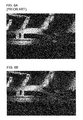
- FIGS. 5A and 5B are exemplary images respectively obtained by a conventional imaging device and an imaging device adopted a dynamic range enhancement apparatus according to an exemplary embodiment of the present invention.
- FIGS. 6A and 6B are another exemplary images respectively obtained by the conventional imaging device and an imaging device adopted a dynamic range enhancement apparatus according to an exemplary embodiment of the present invention.
- FIG. 1A is a block diagram illustrating a configuration of a portable device implemented with a dynamic range enhancement apparatus according to an exemplary embodiment of the present invention.
- the portable device may include a key input unit 101 , a camera unit 103 , a display unit 105 , a memory unit 107 , and a control unit 109 .
- the key input unit 101 is provided with a plurality of keys for receiving user's key input.
- the key input unit 101 is configured to generate a command for capturing an image.
- the camera unit 103 takes an image of an object and generates an image signal.
- the camera unit 103 is provided with an image sensor for converting the optical image to an electric signal and a signal processor for converting the electric signal to a digital signal.
- the image sensor may comprise, for example CCD and CMOS image sensors.
- the camera unit 103 may further include a video processor for generating screen image data.
- the video processor is preferably provided with a video codec for compressing and decompressing the video data so as to be displayed on the display unit 105 .
- the display unit 105 displays operation status of the portable device and various visual information.
- the display unit 105 also displays the image input by the camera unit 103 .
- the display unit 105 is configured to display a gamma corrected image and inverse gamma corrected image.
- the memory unit 107 stores application programs and data associated with the operations of the portable device.
- the control unit 109 controls general operations of the portable device. In this particular exemplary description, the control unit 109 controls to enhance the dynamic range of an input image.
- the control unit is provided with a multi-adaptive compensator 150 .
- the multi-adaptive compensator 150 performs the gamma correction and inverse gamma correction on the image input by the camera unit 103 and expands the dynamic range of the compensated image such that the enhanced image is displayed on the display unit 105 .
- the dynamic enhancement procedure is described in more detail with reference to FIG. 1B .
- the portable device may further include a radio frequency (RF) unit 111 for allowing radio communication.
- the RF unit 111 may include a transceiver or a separate RF transmitter for up-converting and amplifying a signal to be transmitted and an RF receiver for low noise amplifying and down-converting a signal received through an antenna.
- FIG. 1B is a block diagram illustrating a configuration of the multi-adaptive compensator of FIG. 1A .
- the multi-adaptive compensator 150 includes a YUV (luminance and chrominance) transformer 151 , a gamma corrector 153 , an inverse gamma corrector 155 , a weighted averager 157 , and an RGB transformer 159 .
- the multi-adaptive compensator 150 extracts Red, Green, and Blue (RGB) information from the image.
- the RGB information is converted to YUV information.
- Y information represents the brightness
- U information is obtained by subtracting the Y from the blue signal of the original RGB and then scaling
- V information is created by subtracting the Y from the red and scaling by a different factor.
- B U ( B ⁇ Y ) ⁇ 0.493
- V ( R ⁇ Y ) ⁇ 0.877
- the control unit 109 controls the YUV transformer 151 to send the Y information, i.e. brightness, to the gamma corrector 153 and the inverse gamma corrector 155 .
- the gamma correction is performed by transforming the intensity of the light nonlinearly using a nonlinear transfer function.
- human vision operates nonlinearly in response to the brightness.
- a human eye perceives a breakage rather than a smooth change. Accordingly, in order to show the optimal vision quality in the limited expressive information amount, a nonlinear coding should be used.
- the inverse gamma correction is performed by inversing the gamma correction.
- FIG. 2 is a graph illustrating gamma correction and inverse gamma correction curves referred for a dynamic range enhancement method according to an exemplary embodiment of the present invention.
- the gamma corrector 153 brightens the dark area of an image so as to make a sensor response function linear at the dark area.
- the inverse gamma corrector 155 darkens the bright area of the image so as to make a sensor response function linear at the bright area. In this manner, an image input by the camera unit 103 is converted to the YUV information and then compensated by the gamma corrector 153 and inverse gamma corrector 155 .
- FIG. 3A is an image illustrating a result of inverse gamma correction of a dynamic range enhancement method according to an exemplary embodiment of the present invention
- FIG. 3B is an image illustrating a result of gamma correction of a dynamic range enhancement method according an exemplary embodiment of the present invention.
- Information values output by the gamma corrector 153 and inverse gamma corrector 155 are selectively used for compensating the sensor response function.
- the control unit 109 compares variances of the two images of FIGS. 3A and 3B at an identical local area and selects the value greater than the other.
- control unit 109 compares the variances at the areas 1 - a and 2 - a of the inverse gamma corrected image of FIG. 3A with the variances at the corresponding areas 1 - b and 2 - b of the gamma corrected image of FIG. 3B .
- the control unit 109 selects the value of the area 1 - b of the gamma corrected image and the value of the area 2 - a of the inverse gamma corrected image.
- the gamma and inverse gamma corrected images can be, for example, globally compared with each other.
- FIG. 3C is an image illustrating gamma correction and inverse gamma correction areas of an input image obtained through a dynamic range enhancement method according to another exemplary embodiment of the present invention.
- black area is the gamma compensated area
- white area is the inverse gamma compensated area.
- the weighted averager 157 uses the weight average of the two output values. In order to avoid the discontinuity at the boundary between the two areas when using one of the two values, the weighted averager 157 takes a weight average of the two values.
- the average weigh calculator 157 can be implemented, for example, as follows:
- the weighted averager 157 uses the variance as weight such that the larger the variance is, the larger the weight is. Since average weigh calculator 157 has a similar variance at the boundary of two areas, a value close to the linear average of the two areas is reflected to the result. Accordingly, the discontinuous effect at the boundary, appeared when selecting the value comprehensively, can be removed.
- the RGB transformer 159 transforms the YUV information so as to output the RGB information.
- the RGB transformer 159 receives Y′ information output by the weighted averager 157 and UV information output by the YUV transformer 151 and generates RGB information using the Y′ information and the UV information.
- FIG. 4 is a flowchart illustrating exemplary steps of a dynamic range enhancement method according to an exemplary embodiment of the present invention.
- the control unit 109 of the portable device receives RGB information and converts the RGB information into YUV information (S 401 ). At this time, the control unit 109 checks the input of an image captured by the camera and control such that the YUV transformer transforms the RGB information of the input image into the YUV information.
- control unit 109 extracts the Y information (brightness) and UV information (color) from the YUV information (S 403 ).
- control unit 109 controls the YUV transformer 151 to separate the Y information and UV information.
- the control unit 109 only processes the brightness information, i.e. Y information.
- the control unit 109 After separating the Y information from the UV information, the control unit 109 performs gamma correction and inverse gamma correction on the Y information sequentially (S 405 ). That is, the Y information is input to the gamma corrector 153 and the inverse gamma corrector 155 so as to be output in the form of gamma corrected information and inverse gamma corrected information in parallel (see FIG. 2 ).
- the control unit 109 compares the gamma corrected value and the inverse gamma corrected value, selects one of the gamma corrected value and the inverse gamma corrected value, and compensates the sensor response function linearly using the weight average (S 407 ). That is, the control unit 109 compares the values at the same local areas of the gamma corrected image output by the gamma corrector 153 and the inversed gamma corrected image output by the inverse gamma corrector 155 as shown in FIGS. 3A and 3B and selects one of the value. Then, the weighted averager 157 averages weight values to smoothen the discontinuous boundary.
- the control unit 109 transforms the compensated brightness information Y′ and the color information UV so as to be output RGB information (S 409 ).
- the RGB transformer 159 receives the Y′ information output by the weight average 157 and the UV information output by the YUV transformer 151 and generates the RGB information using the Y′ and UV information.
- the RGB information is output by the RGB transformer 150 is output to, for example, display unit 105 under the control of the control unit 109 .
- FIGS. 5A and 5B show exemplary images obtained by a conventional imaging device and an imaging device adopted a dynamic range enhancement apparatus according to an exemplary embodiment of the present invention, respectively.
- FIGS. 6A and 6B show another exemplary images obtained by the conventional imaging device and the imaging device adopted the dynamic range enhancement apparatus according to an exemplary embodiment of the present invention, respectively.
- FIGS. 5A and 6A are photographs processed by the conventional image processing technique
- images of FIGS. 5B and 6B are photographs processed by the dynamic range enhancement method of the present invention.
- the images acquired using the dynamic range enhancement method according to an embodiment of the present invention are superior to the image acquired by the conventional technique, especially in brightness quality.
- the dynamic range enhancement method and apparatus of the present invention expands a dynamic range of an input image by applying a post imaging process without increasing a calculation amount of the imaging device.
Landscapes
- Engineering & Computer Science (AREA)
- Multimedia (AREA)
- Signal Processing (AREA)
- General Engineering & Computer Science (AREA)
- Facsimile Image Signal Circuits (AREA)
- Picture Signal Circuits (AREA)
- Processing Of Color Television Signals (AREA)
- Studio Devices (AREA)
- Image Processing (AREA)
Abstract
Description
Y=0.3R+0.59G+0.11B
U=(B−Y)×0.493
V=(R−Y)×0.877
| if(var(x1)==0&& var(x2)==0) { | ||
| y=(x1+x2)/2 | ||
| } | ||
| else{ | ||
| y=(var(x1)*x1+var(x2)*x2)/(var(x1)+var(x2)) | ||
| } | ||
where x1 denotes the gamma corrected value, x2 denotes the inverse gamma corrected value, var(x1) denotes the variance of the gamma corrected value, and var(x2) denotes the variance of the inverse gamma corrected value. The
R=Y+0.956U+0.621V
G=Y+0.272U+0.647V
B=Y+1.061U+1.703V.
Claims (9)
Applications Claiming Priority (2)
| Application Number | Priority Date | Filing Date | Title |
|---|---|---|---|
| KR1020070122645A KR101437911B1 (en) | 2007-11-29 | 2007-11-29 | Method and apparatus for enhancing dynamic range |
| KR2007-0122645 | 2007-11-29 |
Publications (2)
| Publication Number | Publication Date |
|---|---|
| US20090141151A1 US20090141151A1 (en) | 2009-06-04 |
| US8072516B2 true US8072516B2 (en) | 2011-12-06 |
Family
ID=40675307
Family Applications (1)
| Application Number | Title | Priority Date | Filing Date |
|---|---|---|---|
| US12/315,028 Expired - Fee Related US8072516B2 (en) | 2007-11-29 | 2008-11-26 | Dynamic range enhancement method and apparatus |
Country Status (2)
| Country | Link |
|---|---|
| US (1) | US8072516B2 (en) |
| KR (1) | KR101437911B1 (en) |
Cited By (1)
| Publication number | Priority date | Publication date | Assignee | Title |
|---|---|---|---|---|
| US20110187898A1 (en) * | 2010-01-29 | 2011-08-04 | Samsung Electronics Co., Ltd. | Photographing method and apparatus and a recording medium storing a program for executing the method |
Families Citing this family (3)
| Publication number | Priority date | Publication date | Assignee | Title |
|---|---|---|---|---|
| TWI513310B (en) * | 2013-07-12 | 2015-12-11 | Univ Nat Yunlin Sci & Tech | Device and method for expanding dynamic range of camera |
| KR102160247B1 (en) * | 2014-07-11 | 2020-09-25 | 삼성전자주식회사 | Electronic apparatus and Method for controlling the electronic apparatus thereof |
| US9852531B2 (en) * | 2014-07-11 | 2017-12-26 | Samsung Electronics Co., Ltd. | Electronic apparatus and method for controlling the same |
Citations (8)
| Publication number | Priority date | Publication date | Assignee | Title |
|---|---|---|---|---|
| US20020181000A1 (en) * | 2001-03-15 | 2002-12-05 | Kenji Fukasawa | Image processing apparatus |
| US6492868B2 (en) | 2000-08-14 | 2002-12-10 | Larry Kirn | Dynamic range enhancement technique |
| US20040119874A1 (en) * | 2002-09-20 | 2004-06-24 | Toshie Imai | Backlight adjustment processing of image using image generation record information |
| US20060164524A1 (en) * | 2005-01-25 | 2006-07-27 | Sharp Kabushiki Kaisha | Brightness level converting apparatus, brightness level converting method, solid-state image pickup apparatus, brightness level converting program, and recording medium |
| US20070153305A1 (en) * | 2006-01-03 | 2007-07-05 | Reid Russell M | Exposure adjustment of an image using G+/G- curve |
| US7330286B2 (en) * | 2000-10-13 | 2008-02-12 | Seiko Epson Corporation | Apparatus, method and computer program product for providing output image adjustment for image files |
| US7511770B2 (en) * | 2004-09-21 | 2009-03-31 | Thomson Licensing | Method and device for processing a video signal aimed at compensating for the defects of display devices |
| US7933445B2 (en) * | 2007-01-09 | 2011-04-26 | Sharp Laboratories Of America, Inc. | Color gamut mapping/enhancement technique using skin color detection |
-
2007
- 2007-11-29 KR KR1020070122645A patent/KR101437911B1/en not_active Expired - Fee Related
-
2008
- 2008-11-26 US US12/315,028 patent/US8072516B2/en not_active Expired - Fee Related
Patent Citations (8)
| Publication number | Priority date | Publication date | Assignee | Title |
|---|---|---|---|---|
| US6492868B2 (en) | 2000-08-14 | 2002-12-10 | Larry Kirn | Dynamic range enhancement technique |
| US7330286B2 (en) * | 2000-10-13 | 2008-02-12 | Seiko Epson Corporation | Apparatus, method and computer program product for providing output image adjustment for image files |
| US20020181000A1 (en) * | 2001-03-15 | 2002-12-05 | Kenji Fukasawa | Image processing apparatus |
| US20040119874A1 (en) * | 2002-09-20 | 2004-06-24 | Toshie Imai | Backlight adjustment processing of image using image generation record information |
| US7511770B2 (en) * | 2004-09-21 | 2009-03-31 | Thomson Licensing | Method and device for processing a video signal aimed at compensating for the defects of display devices |
| US20060164524A1 (en) * | 2005-01-25 | 2006-07-27 | Sharp Kabushiki Kaisha | Brightness level converting apparatus, brightness level converting method, solid-state image pickup apparatus, brightness level converting program, and recording medium |
| US20070153305A1 (en) * | 2006-01-03 | 2007-07-05 | Reid Russell M | Exposure adjustment of an image using G+/G- curve |
| US7933445B2 (en) * | 2007-01-09 | 2011-04-26 | Sharp Laboratories Of America, Inc. | Color gamut mapping/enhancement technique using skin color detection |
Cited By (2)
| Publication number | Priority date | Publication date | Assignee | Title |
|---|---|---|---|---|
| US20110187898A1 (en) * | 2010-01-29 | 2011-08-04 | Samsung Electronics Co., Ltd. | Photographing method and apparatus and a recording medium storing a program for executing the method |
| US8619151B2 (en) * | 2010-01-29 | 2013-12-31 | Samsung Electronics Co., Ltd. | Photographing method and apparatus providing correction of object shadows, and a recording medium storing a program for executing the method |
Also Published As
| Publication number | Publication date |
|---|---|
| KR20090055816A (en) | 2009-06-03 |
| US20090141151A1 (en) | 2009-06-04 |
| KR101437911B1 (en) | 2014-09-05 |
Similar Documents
| Publication | Publication Date | Title |
|---|---|---|
| US11849224B2 (en) | Global tone mapping | |
| KR100467610B1 (en) | Method and apparatus for improvement of digital image quality | |
| JP5003196B2 (en) | Image processing apparatus and method, and program | |
| US8228438B2 (en) | Image processing method capable of improving the display quality of image frames | |
| US8639050B2 (en) | Dynamic adjustment of noise filter strengths for use with dynamic range enhancement of images | |
| US8169500B2 (en) | Dynamic range compression apparatus, dynamic range compression method, computer-readable recording medium, integrated circuit, and imaging apparatus | |
| CN100366052C (en) | Image processing device and method | |
| US7920183B2 (en) | Image processing device and digital camera | |
| US20110229019A1 (en) | Scene Adaptive Brightness/Contrast Enhancement | |
| JP2007049540A (en) | Image processing apparatus and method, recording medium, and program | |
| WO2019104047A1 (en) | Global tone mapping | |
| US12206996B2 (en) | Tone mapping for image capture | |
| US7710470B2 (en) | Image processing apparatus that reduces noise, image processing method that reduces noise, electronic camera that reduces noise, and scanner that reduces noise | |
| US20250330718A1 (en) | Image sensor processing merged image and image processing system comprising the same | |
| CN103826113A (en) | Color reducing method and device | |
| US11637963B2 (en) | Image sensor and image processing system comprising the same | |
| US8115826B2 (en) | Image processing apparatus, imaging apparatus, method and program | |
| US8072516B2 (en) | Dynamic range enhancement method and apparatus | |
| KR100916104B1 (en) | Luma adaptation for digital image processing | |
| JPWO2009093294A1 (en) | Image signal processing apparatus and image signal processing program | |
| US20120274816A1 (en) | Apparatus and method for processing image in digital camera | |
| JP4340303B2 (en) | Image processing apparatus and image processing program | |
| US7352397B2 (en) | Circuit and method for contour enhancement | |
| JP2008219289A (en) | Video correction device, video display device, imaging apparatus and video correction program | |
| US20100002145A1 (en) | Adaptive optimization of a video signal |
Legal Events
| Date | Code | Title | Description |
|---|---|---|---|
| AS | Assignment |
Owner name: SAMSUNG ELECTRONICS CO., LTD., KOREA, REPUBLIC OF Free format text: ASSIGNMENT OF ASSIGNORS INTEREST;ASSIGNORS:PARK, MIN KYU;PARK, HYUN HEE;CHO, SUNG DAE;AND OTHERS;REEL/FRAME:021946/0027 Effective date: 20081125 |
|
| ZAAA | Notice of allowance and fees due |
Free format text: ORIGINAL CODE: NOA |
|
| ZAAB | Notice of allowance mailed |
Free format text: ORIGINAL CODE: MN/=. |
|
| ZAAA | Notice of allowance and fees due |
Free format text: ORIGINAL CODE: NOA |
|
| ZAAB | Notice of allowance mailed |
Free format text: ORIGINAL CODE: MN/=. |
|
| STCF | Information on status: patent grant |
Free format text: PATENTED CASE |
|
| FEPP | Fee payment procedure |
Free format text: PAYOR NUMBER ASSIGNED (ORIGINAL EVENT CODE: ASPN); ENTITY STATUS OF PATENT OWNER: LARGE ENTITY |
|
| AS | Assignment |
Owner name: INDUSTRY-ACADEMIC COOPERATION FOUNDATION, YONSEI U Free format text: ASSIGNMENT OF ASSIGNORS INTEREST;ASSIGNOR:SAMSUNG ELECTRONICS CO., LTD.;REEL/FRAME:028340/0111 Effective date: 20120604 Owner name: SAMSUNG ELECTRONICS CO., LTD., KOREA, REPUBLIC OF Free format text: ASSIGNMENT OF ASSIGNORS INTEREST;ASSIGNOR:SAMSUNG ELECTRONICS CO., LTD.;REEL/FRAME:028340/0111 Effective date: 20120604 |
|
| FPAY | Fee payment |
Year of fee payment: 4 |
|
| MAFP | Maintenance fee payment |
Free format text: PAYMENT OF MAINTENANCE FEE, 8TH YEAR, LARGE ENTITY (ORIGINAL EVENT CODE: M1552); ENTITY STATUS OF PATENT OWNER: LARGE ENTITY Year of fee payment: 8 |
|
| FEPP | Fee payment procedure |
Free format text: MAINTENANCE FEE REMINDER MAILED (ORIGINAL EVENT CODE: REM.); ENTITY STATUS OF PATENT OWNER: LARGE ENTITY |
|
| LAPS | Lapse for failure to pay maintenance fees |
Free format text: PATENT EXPIRED FOR FAILURE TO PAY MAINTENANCE FEES (ORIGINAL EVENT CODE: EXP.); ENTITY STATUS OF PATENT OWNER: LARGE ENTITY |
|
| STCH | Information on status: patent discontinuation |
Free format text: PATENT EXPIRED DUE TO NONPAYMENT OF MAINTENANCE FEES UNDER 37 CFR 1.362 |
|
| FP | Lapsed due to failure to pay maintenance fee |
Effective date: 20231206 |