US8072506B2 - Method for flicker detection in image signal - Google Patents
Method for flicker detection in image signal Download PDFInfo
- Publication number
- US8072506B2 US8072506B2 US11/193,673 US19367305A US8072506B2 US 8072506 B2 US8072506 B2 US 8072506B2 US 19367305 A US19367305 A US 19367305A US 8072506 B2 US8072506 B2 US 8072506B2
- Authority
- US
- United States
- Prior art keywords
- flicker
- frame data
- difference
- current frame
- motion
- Prior art date
- Legal status (The legal status is an assumption and is not a legal conclusion. Google has not performed a legal analysis and makes no representation as to the accuracy of the status listed.)
- Active, expires
Links
- 238000001514 detection method Methods 0.000 title claims abstract description 24
- 238000000034 method Methods 0.000 title claims description 47
- 230000033001 locomotion Effects 0.000 claims abstract description 84
- 238000006073 displacement reaction Methods 0.000 claims abstract description 26
- 238000001914 filtration Methods 0.000 claims description 6
- 238000010586 diagram Methods 0.000 description 10
- 238000004364 calculation method Methods 0.000 description 5
- 206010044565 Tremor Diseases 0.000 description 3
- 230000000295 complement effect Effects 0.000 description 1
- 230000006870 function Effects 0.000 description 1
- 230000010354 integration Effects 0.000 description 1
- 230000001788 irregular Effects 0.000 description 1
- 229910044991 metal oxide Inorganic materials 0.000 description 1
- 150000004706 metal oxides Chemical class 0.000 description 1
- 238000012986 modification Methods 0.000 description 1
- 230000004048 modification Effects 0.000 description 1
- 230000002093 peripheral effect Effects 0.000 description 1
- 239000004065 semiconductor Substances 0.000 description 1
Images


Classifications
-
- H—ELECTRICITY
- H04—ELECTRIC COMMUNICATION TECHNIQUE
- H04N—PICTORIAL COMMUNICATION, e.g. TELEVISION
- H04N5/00—Details of television systems
- H04N5/14—Picture signal circuitry for video frequency region
- H04N5/144—Movement detection
- H04N5/145—Movement estimation
-
- H—ELECTRICITY
- H04—ELECTRIC COMMUNICATION TECHNIQUE
- H04N—PICTORIAL COMMUNICATION, e.g. TELEVISION
- H04N5/00—Details of television systems
- H04N5/14—Picture signal circuitry for video frequency region
- H04N5/21—Circuitry for suppressing or minimising disturbance, e.g. moiré or halo
-
- H—ELECTRICITY
- H04—ELECTRIC COMMUNICATION TECHNIQUE
- H04N—PICTORIAL COMMUNICATION, e.g. TELEVISION
- H04N23/00—Cameras or camera modules comprising electronic image sensors; Control thereof
- H04N23/60—Control of cameras or camera modules
- H04N23/68—Control of cameras or camera modules for stable pick-up of the scene, e.g. compensating for camera body vibrations
- H04N23/681—Motion detection
- H04N23/6811—Motion detection based on the image signal
-
- H—ELECTRICITY
- H04—ELECTRIC COMMUNICATION TECHNIQUE
- H04N—PICTORIAL COMMUNICATION, e.g. TELEVISION
- H04N23/00—Cameras or camera modules comprising electronic image sensors; Control thereof
- H04N23/60—Control of cameras or camera modules
- H04N23/68—Control of cameras or camera modules for stable pick-up of the scene, e.g. compensating for camera body vibrations
- H04N23/681—Motion detection
- H04N23/6812—Motion detection based on additional sensors, e.g. acceleration sensors
-
- H—ELECTRICITY
- H04—ELECTRIC COMMUNICATION TECHNIQUE
- H04N—PICTORIAL COMMUNICATION, e.g. TELEVISION
- H04N23/00—Cameras or camera modules comprising electronic image sensors; Control thereof
- H04N23/70—Circuitry for compensating brightness variation in the scene
- H04N23/745—Detection of flicker frequency or suppression of flicker wherein the flicker is caused by illumination, e.g. due to fluorescent tube illumination or pulsed LED illumination
-
- H—ELECTRICITY
- H04—ELECTRIC COMMUNICATION TECHNIQUE
- H04N—PICTORIAL COMMUNICATION, e.g. TELEVISION
- H04N25/00—Circuitry of solid-state image sensors [SSIS]; Control thereof
- H04N25/70—SSIS architectures; Circuits associated therewith
- H04N25/76—Addressed sensors, e.g. MOS or CMOS sensors
Definitions
- the present invention relates to a flicker detection method in an image signal; and, more particularly, to an effective method for a flicker detection with performing a motion compensation between frames of image data constituted with plural image signals.
- CCD Charge-coupled devices
- CMOS complementary metal oxide semiconductor
- the CCD sensors offer superior image performance and flexibility.
- the size of the CCD is large compare with the CMOS image sensor.
- the CMOS image sensors offer more integration, lower power dissipation, and smaller system size although image quality and flexibility of the CMOS image sensor are far below than the CCD.
- the CMOS image sensors are suitable to high-volume, space-constrained applications where image quality is not critical, e.g., a camera of a mobile telephone, a security camera, a PC peripheral, toys, and some automotive applications.
- great advances have been achieved and CMOS image sensors with quality comparable to CCD sensors can be produced. Because of the above mentioned advantages, the CMOS image sensor is, therefore, used extensively.
- a flicker can be generated.
- each line of a pixel array in the CMOS image sensor receives different light sources, each line has different luminance.
- an additional band is appeared in each line on an image. The additional band is called as the flicker.
- FIG. 1 is a diagram explaining a case when a flicker occurs.
- an amount of energy inputted to each line of a CMOS image sensor varies according to a quantity of inputted light and an exposing time of the CMOS image sensor. Due to a difference of the amount of energy inputted to each line, the flicker occurs in the CMOS image sensor. This flicker degrades a quality of the image. Thus, the flicker should be remedied to thereby improve the quality of the image.
- an object of the present invention to provide a flicker detection method performing a motion compensation.
- a flicker detection method for detecting a flicker from an image signal outputted through M ⁇ N pixels.
- the flicker detection of the present invention includes the steps of: (a) calculating a luminance difference between neighboring pixels; (b) summing up the luminance difference in a specific direction if the difference is greater than a threshold value; (c) performing a motion estimation by using a sum calculated through step (b) to thereby calculate a motion displacement; (d) performing a motion compensation to a current frame data by using the motion displacement; (e) calculating a difference between a previous frame data and the compensated current frame data; and (f) detecting the flicker by using the difference calculated in step (e).
- FIG. 1 is a diagram explaining a case when a flicker occurs
- FIG. 2 is a flow chart describing a flicker detection algorithm in accordance with the present invention
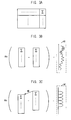
- FIGS. 3A to 3C are diagrams explaining a data process method for use in a motion estimation
- FIG. 4 is a diagram showing a motion estimation process
- FIG. 5 is a magnified diagram of W 2 shown in FIG. 3C ;
- FIG. 6 is a diagram showing an operation result of the present invention.
- the present invention is based on a method of detecting a flicker from an image.
- the method should detect only the flicker from an image difference between a previous frame and a current frame including both the flicker and motions, e.g., a hand tremble.
- the present invention performs a motion estimation to thereby compensate the motions.
- a motion estimation By compensating the motions through the motion estimation, most distortion of image caused by the motions can be removed from the image difference and, thus, a difference caused by the flicker can be obtained accurately.
- the present invention performs a predetermined operation to thereby perform the motion estimation with small amount of data. Through the operation, the minimum data necessary for the motion estimation is selected and used for the motion estimation.
- a flicker is occurred because a frequency of a light source and a frequency of an exposing time of a CMOS image sensor are different.
- a fluorescent lamp is operated in a low frequency, e.g., 50 Hz or 60 Hz.
- the exposing time of the CMOS image sensor is generally dozens of milli-seconds (ms).
- the flicker can be occurs.
- the present invention detects the flicker as following sequence: obtaining a data required for a motion estimation; performing the motion estimation; performing a motion compensation; calculating a difference between a motion compensated data and a previous data; filtering the difference by using a low pass filter to thereby detect local minima of the difference; analyzing a distance of the two local minima to thereby obtain a period of the difference; and determining whether the flicker occurs or not by analyzing the period.
- FIG. 2 is a flow chart describing a flicker detection algorithm in accordance with the present invention.
- a method for detecting a flicker from an image signal outputted in M ⁇ N pixels is as follows (herein, the M and N are natural numbers): calculating a luminance difference between neighboring pixel data (S 201 ); comparing the luminance difference with a threshold value ⁇ Th (S 202 ); adding the luminance difference in a specific direction, e.g., a row direction and a column direction when the luminance difference is greater than the threshold value ⁇ Th (S 203 ); discarding the luminance difference when the luminance difference is less than the threshold value ⁇ Th (S 204 ); performing a motion estimation (S 205 ); calculating a motion displacement MD (S 206 ); performing a motion compensation about a present frame data by using the motion displacement MD (S 207 ); calculating a difference between the compensated current frame data and a previous frame data in the specific direction, e.g., the row direction and the column direction (S 208 ); and detecting the flicker by using the difference between the frame data (S
- the flicker in the image signal is partially removed. Meanwhile, instead of comparing every pixel data in a frame, only the neighboring pixel data are compared to thereby calculate the luminance difference. Thus, the motion estimation can be performed by using one line memory instead of using the whole frame memory.
- a sum of absolute difference SAD is calculated by moving a search window in a search range while an initial position of the motion estimation which is randomly chosen is set as a standard.
- a minimum factor of the SAD is selected as the motion displacement MD.
- the motion compensation of the current frame data is actually performed by moving the previous frame data as much as the motion displacement of the current frame data.
- the difference between the frame data is low filtered to thereby find local minima of the difference. Then, by finding a distance between two local minima, a flicker period is calculated. The flicker period is compared with a predetermined detection period for thereby determining whether the flicker is occurred or not. If the flicker period coincides with the detection period, it is considered that the flicker is occurred.
- the motion estimation is used importantly in standards for coded representation of digital audio and video, e.g., MPEG-2, H.263, and H.264.
- the motion estimation refers a method of compensating displacements between consecutive video frames induced by moving objects and scene changes to thereby reduce the image difference between a current frame and a previous frame.
- FIGS. 3A to 3C are diagrams explaining a data process method for use in the motion estimation.
- a frame memory is required to perform the motion estimation.
- it is hard to implement a one-chip COS image sensor including the frame memory because a hardware burden is overgrown.
- the present invention uses a line memory for performing the motion estimation by adding a difference between each neighboring pixels in a specific direction, e.g., a row direction and a column direction.
- a specific direction e.g., a row direction and a column direction.
- the present invention performs the addition in the row direction.
- Equation 1 a new data S T (j) for use in the motion estimation is defined by Equation 1 below.
- Equation 1 p i,j,T denotes a pixel arranged in an i th row and a j th column of a T th frame; L denotes a width of the frame; and j denotes a height of the frame.
- Equation 2 a function ⁇ is defined by Equation 2 below.
- ⁇ Th denotes a predetermined threshold value.
- a pixel having great difference with neighboring pixels i.e., having a large
- Equation 3 After collecting the current frame data and the previous frame data through Equation 1, the motion estimation is performed through the following Equation 3 below.
- Equation 3 ‘BS’ denotes a block size that the motion estimation will be performed; ‘off’ denotes an initial position of the motion estimation; ‘SR’ denotes the search range.
- FIG. 3B describes the calculation of the difference between the frame data without compensating the motion displacement MD.
- W 1 a result of the calculation without compensating the motion displacement MD is irregular wave form and, therefore, it is impossible to find a period.
- FIG. 3C shows the calculation of the difference between the frame data with compensating the motion displacement MD to thereby detect the flicker.
- a result of the calculation with the motion compensation has a predetermined period. This period is used to detect the flicker.
- FIG. 4 is a diagram showing a motion estimation process.
- the motion estimation is performed by passing through a scan and a SAD calculation.
- an area drawn a deviant crease represents the search window SW, i.e., the block size BS.
- the search window SW can move bidirectionally, for example, from upside to bottom and vice versa as shown in FIG. 4 .
- Equation 4 the minimum value of the SAD is able to be found by an operator ‘min’.
- the final motion displacement MD value is determined by an operator ‘arg’ which returns an argument v having the minimum SAD value.
- the motion compensation does not use the data generated via Equation 1 but use a value generated by Equation 5 below.
- U T (j) is a sum of the pixels in one row of a certain frame.
- a flicker period is determined.
- Equation 6 includes many noises.
- the noises are filtered by a low pass filter. If a period of local minima of the low filtered data, i.e., the flicker period corresponds to a predetermined detection period, the filtered data is determined as the flicker. When a number of the local minima whose flicker period is corresponding to the detection period in a certain frame is greater than a predetermined number, the corresponding frame is considered that the flicker is occurred.
- FIG. 5 is a magnified diagram of W shown in FIG. 3C to thereby explain a detection of the flicker period by using the local minima of the compensation error and a determination of the flicker.
- Ppt denotes a previous value of a wave
- Cpt denotes a current value of the wave
- Fpt denotes a following value of the wave.
- the current value Cpt is the least value from the Ppt, Cpt, and Fpt
- the current value Cpt becomes the local minima.
- a period of the local minima, i.e., the flicker period is counted to thereby detect the flicker.
- FIG. 6 is a diagram showing an operation result of the present invention.
- a horizontal axis represents a frame number; a vertical axis represents the number of local minima whose flicker period is different from the detection period.
- the flicker period is detected by the flicker detection method performing the motion compensation. If the number of local minima whose flicker period is different from the detection period in a certain frame is more than 3, it is determined that the frame does not include the flicker. As shown in FIG. 8 , the present invention correctly detects the flickers in 89 frames of 100 frames.
- the present invention performs the flicker detection unlike the conventional art that detects the flicker simply by calculating the difference between the previous frame and the current frame. That is, the present invention compensates the motion, e.g., a hand tremble to thereby detect the flicker by using the compensated frame data. Accordingly, the present invention is able to detect the flicker reliably and, further, improve the quality of an image.
Landscapes
- Engineering & Computer Science (AREA)
- Multimedia (AREA)
- Signal Processing (AREA)
- Image Analysis (AREA)
- Studio Devices (AREA)
- Picture Signal Circuits (AREA)
- Control Of Indicators Other Than Cathode Ray Tubes (AREA)
Abstract
Description
MD=arg(min{SAD(v)}) (Eq. 4)
ε(j)=U T(j)−U T-1(j+MD) (Eq. 6)
Claims (31)
Priority Applications (1)
| Application Number | Priority Date | Filing Date | Title |
|---|---|---|---|
| US13/302,033 US9137424B2 (en) | 2004-07-29 | 2011-11-22 | Method for flicker detection in image signal |
Applications Claiming Priority (2)
| Application Number | Priority Date | Filing Date | Title |
|---|---|---|---|
| KR1020040059479A KR100557660B1 (en) | 2004-07-29 | 2004-07-29 | Flicker Detection Method in Image Signal |
| KR2004-0059479 | 2004-07-29 |
Related Child Applications (1)
| Application Number | Title | Priority Date | Filing Date |
|---|---|---|---|
| US13/302,033 Continuation US9137424B2 (en) | 2004-07-29 | 2011-11-22 | Method for flicker detection in image signal |
Publications (2)
| Publication Number | Publication Date |
|---|---|
| US20060061669A1 US20060061669A1 (en) | 2006-03-23 |
| US8072506B2 true US8072506B2 (en) | 2011-12-06 |
Family
ID=36073512
Family Applications (2)
| Application Number | Title | Priority Date | Filing Date |
|---|---|---|---|
| US11/193,673 Active 2029-02-28 US8072506B2 (en) | 2004-07-29 | 2005-07-28 | Method for flicker detection in image signal |
| US13/302,033 Expired - Lifetime US9137424B2 (en) | 2004-07-29 | 2011-11-22 | Method for flicker detection in image signal |
Family Applications After (1)
| Application Number | Title | Priority Date | Filing Date |
|---|---|---|---|
| US13/302,033 Expired - Lifetime US9137424B2 (en) | 2004-07-29 | 2011-11-22 | Method for flicker detection in image signal |
Country Status (2)
| Country | Link |
|---|---|
| US (2) | US8072506B2 (en) |
| KR (1) | KR100557660B1 (en) |
Cited By (2)
| Publication number | Priority date | Publication date | Assignee | Title |
|---|---|---|---|---|
| US20100123810A1 (en) * | 2008-11-14 | 2010-05-20 | Ati Technologies Ulc | Flicker Detection Circuit for Imaging Sensors that Employ Rolling Shutters |
| US11176868B2 (en) * | 2020-02-13 | 2021-11-16 | Anapass Inc. | Device and method for driving display |
Families Citing this family (26)
| Publication number | Priority date | Publication date | Assignee | Title |
|---|---|---|---|---|
| JP4335849B2 (en) * | 2005-06-13 | 2009-09-30 | 富士通マイクロエレクトロニクス株式会社 | Imaging device capable of flicker detection |
| JP4904749B2 (en) * | 2005-09-08 | 2012-03-28 | ソニー株式会社 | Flicker reduction method, flicker reduction circuit, and imaging apparatus |
| JP4354449B2 (en) * | 2005-10-26 | 2009-10-28 | オリンパス株式会社 | Display image imaging method and apparatus |
| JP4621585B2 (en) * | 2005-12-15 | 2011-01-26 | 株式会社東芝 | Image processing apparatus and image processing method |
| KR100721664B1 (en) | 2005-12-22 | 2007-05-23 | 매그나칩 반도체 유한회사 | Flicker Detection Circuit and Method of Image Sensor |
| US7860334B2 (en) * | 2006-02-09 | 2010-12-28 | Qualcomm Incorporated | Adaptive image filter for filtering image information |
| KR101254216B1 (en) | 2006-08-21 | 2013-04-23 | 엘지전자 주식회사 | Method of removing a flicker noise of a mobile communication terminal and the mobile communication terminal thereof |
| KR100891434B1 (en) * | 2007-05-16 | 2009-04-03 | 주식회사 코아로직 | Flicker noise detection device, method and recording medium thereof |
| JP4836896B2 (en) * | 2007-08-27 | 2011-12-14 | 三洋電機株式会社 | Video camera |
| TW200926767A (en) * | 2007-12-07 | 2009-06-16 | Sunplus Mmedia Inc | Automatic flicker detection and correction apparatus and method in a video capture device |
| US8755613B2 (en) * | 2008-01-17 | 2014-06-17 | Thomson Licensing | Method for measuring flicker |
| JP5035025B2 (en) * | 2008-03-03 | 2012-09-26 | ソニー株式会社 | Image processing apparatus, flicker reduction method, imaging apparatus, and flicker reduction program |
| JP2010114674A (en) * | 2008-11-06 | 2010-05-20 | Sanyo Electric Co Ltd | Video camera |
| JP2011030093A (en) * | 2009-07-28 | 2011-02-10 | Sanyo Electric Co Ltd | Video camera |
| TWI413023B (en) * | 2010-03-30 | 2013-10-21 | Novatek Microelectronics Corp | Method and apparatus for motion detection |
| US8711245B2 (en) * | 2011-03-18 | 2014-04-29 | Digitaloptics Corporation Europe Ltd. | Methods and systems for flicker correction |
| WO2012147337A1 (en) * | 2011-04-28 | 2012-11-01 | オリンパス株式会社 | Flicker detection device, flicker detection method, and flicker detection program |
| US9247109B2 (en) | 2013-03-15 | 2016-01-26 | Samsung Electronics Co., Ltd. | Performing spatial and temporal image contrast detection in pixel array |
| CN104301618B (en) | 2013-07-19 | 2017-11-14 | 富士通株式会社 | Flicker detection method and flicker detection equipment |
| CN104301617B (en) * | 2013-07-19 | 2017-09-22 | 富士通株式会社 | Flicker detection method and flicker detection equipment |
| CN104125401B (en) * | 2014-07-22 | 2017-08-25 | 广州三星通信技术研究有限公司 | Control the method and filming apparatus of image working sensor |
| CN104486616B (en) * | 2014-12-11 | 2017-05-10 | 武汉精测电子技术股份有限公司 | Device for quality detection of TTL (transistor-transistor logic) video signals |
| CN104469351B (en) * | 2014-12-11 | 2017-12-12 | 武汉精测电子技术股份有限公司 | A kind of method of LVDS vision signals caused by detection video source |
| KR20160077664A (en) | 2014-12-24 | 2016-07-04 | 이승태 | Flexible reflective reflector grooved |
| CN109671050B (en) * | 2018-11-09 | 2022-11-22 | 中国航空工业集团公司洛阳电光设备研究所 | Method for detecting scintillation bad elements of linear detector |
| US12412247B2 (en) | 2021-09-23 | 2025-09-09 | Samsung Electronics Co., Ltd. | Efficient flicker suppression for single image super-resolution |
Citations (12)
| Publication number | Priority date | Publication date | Assignee | Title |
|---|---|---|---|---|
| US5325125A (en) * | 1992-09-24 | 1994-06-28 | Matsushita Electric Corporation Of America | Intra-frame filter for video compression systems |
| US5819035A (en) * | 1995-10-20 | 1998-10-06 | Matsushita Electric Industrial Co., Ltd. | Post-filter for removing ringing artifacts of DCT coding |
| US20040016919A1 (en) * | 2002-07-25 | 2004-01-29 | Fujitsu Limited | Solid-state image sensor |
| US20040047419A1 (en) * | 2002-09-09 | 2004-03-11 | Tsukimi Wakabayashi | Apparatus and computer program for detecting motion in image frame |
| US6845180B2 (en) * | 2001-03-16 | 2005-01-18 | Sharp Laboratories Of America, Inc. | Predicting ringing artifacts in digital images |
| US7046289B2 (en) * | 2001-06-06 | 2006-05-16 | Minolta Co., Ltd. | Automatic focusing device, camera, and automatic focusing method |
| US7106368B2 (en) * | 2001-04-26 | 2006-09-12 | Fujitsu Limited | Method of reducing flicker noises of X-Y address type solid-state image pickup device |
| US7176982B2 (en) * | 2003-05-23 | 2007-02-13 | Huaya Microelectronics, Ltd. | Recursive noise reduction with still pixel detection |
| US7187405B2 (en) * | 2001-10-02 | 2007-03-06 | Avago Technologies General Ip (Singapore) Pte. Ltd. | Automatic flicker frequency detection device and method |
| US20070146500A1 (en) * | 2005-12-22 | 2007-06-28 | Magnachip Semiconductor Ltd. | Flicker detecting circuit and method in image sensor |
| US7259794B2 (en) * | 2003-09-25 | 2007-08-21 | Himax Technologies Limited | De-interlacing device and method therefor |
| US7538799B2 (en) * | 2005-01-14 | 2009-05-26 | Freescale Semiconductor, Inc. | System and method for flicker detection in digital imaging |
Family Cites Families (7)
| Publication number | Priority date | Publication date | Assignee | Title |
|---|---|---|---|---|
| JPH05181970A (en) * | 1991-12-27 | 1993-07-23 | Toshiba Corp | Moving image processor |
| KR100623404B1 (en) * | 1998-03-23 | 2006-09-13 | 코닌클리케 필립스 일렉트로닉스 엔.브이. | Display driven |
| JP3539901B2 (en) | 1999-10-08 | 2004-07-07 | 松下電器産業株式会社 | Flicker detection / correction apparatus and flicker detection / correction method |
| JP3476400B2 (en) | 1999-10-19 | 2003-12-10 | 松下電器産業株式会社 | Flicker detection / correction apparatus and flicker detection / correction method |
| JP3823314B2 (en) | 2001-12-18 | 2006-09-20 | ソニー株式会社 | Imaging signal processing apparatus and flicker detection method |
| JP3928424B2 (en) | 2001-12-26 | 2007-06-13 | コニカミノルタビジネステクノロジーズ株式会社 | Flicker correction for movies |
| JP2003198932A (en) * | 2001-12-27 | 2003-07-11 | Sharp Corp | Flicker correction device, flicker correction method, and recording medium storing flicker correction program |
-
2004
- 2004-07-29 KR KR1020040059479A patent/KR100557660B1/en not_active Expired - Fee Related
-
2005
- 2005-07-28 US US11/193,673 patent/US8072506B2/en active Active
-
2011
- 2011-11-22 US US13/302,033 patent/US9137424B2/en not_active Expired - Lifetime
Patent Citations (12)
| Publication number | Priority date | Publication date | Assignee | Title |
|---|---|---|---|---|
| US5325125A (en) * | 1992-09-24 | 1994-06-28 | Matsushita Electric Corporation Of America | Intra-frame filter for video compression systems |
| US5819035A (en) * | 1995-10-20 | 1998-10-06 | Matsushita Electric Industrial Co., Ltd. | Post-filter for removing ringing artifacts of DCT coding |
| US6845180B2 (en) * | 2001-03-16 | 2005-01-18 | Sharp Laboratories Of America, Inc. | Predicting ringing artifacts in digital images |
| US7106368B2 (en) * | 2001-04-26 | 2006-09-12 | Fujitsu Limited | Method of reducing flicker noises of X-Y address type solid-state image pickup device |
| US7046289B2 (en) * | 2001-06-06 | 2006-05-16 | Minolta Co., Ltd. | Automatic focusing device, camera, and automatic focusing method |
| US7187405B2 (en) * | 2001-10-02 | 2007-03-06 | Avago Technologies General Ip (Singapore) Pte. Ltd. | Automatic flicker frequency detection device and method |
| US20040016919A1 (en) * | 2002-07-25 | 2004-01-29 | Fujitsu Limited | Solid-state image sensor |
| US20040047419A1 (en) * | 2002-09-09 | 2004-03-11 | Tsukimi Wakabayashi | Apparatus and computer program for detecting motion in image frame |
| US7176982B2 (en) * | 2003-05-23 | 2007-02-13 | Huaya Microelectronics, Ltd. | Recursive noise reduction with still pixel detection |
| US7259794B2 (en) * | 2003-09-25 | 2007-08-21 | Himax Technologies Limited | De-interlacing device and method therefor |
| US7538799B2 (en) * | 2005-01-14 | 2009-05-26 | Freescale Semiconductor, Inc. | System and method for flicker detection in digital imaging |
| US20070146500A1 (en) * | 2005-12-22 | 2007-06-28 | Magnachip Semiconductor Ltd. | Flicker detecting circuit and method in image sensor |
Cited By (3)
| Publication number | Priority date | Publication date | Assignee | Title |
|---|---|---|---|---|
| US20100123810A1 (en) * | 2008-11-14 | 2010-05-20 | Ati Technologies Ulc | Flicker Detection Circuit for Imaging Sensors that Employ Rolling Shutters |
| US8441551B2 (en) * | 2008-11-14 | 2013-05-14 | Ati Technologies Ulc | Flicker detection circuit for imaging sensors that employ rolling shutters |
| US11176868B2 (en) * | 2020-02-13 | 2021-11-16 | Anapass Inc. | Device and method for driving display |
Also Published As
| Publication number | Publication date |
|---|---|
| US20060061669A1 (en) | 2006-03-23 |
| US9137424B2 (en) | 2015-09-15 |
| KR20060010890A (en) | 2006-02-03 |
| KR100557660B1 (en) | 2006-03-10 |
| US20120081571A1 (en) | 2012-04-05 |
Similar Documents
| Publication | Publication Date | Title |
|---|---|---|
| US9137424B2 (en) | Method for flicker detection in image signal | |
| JP4395077B2 (en) | Image stabilization system and method | |
| US8054881B2 (en) | Video stabilization in real-time using computationally efficient corner detection and correspondence | |
| EP2169945B1 (en) | Image processing apparatus and method for detection and correction of camera shake | |
| JP2008541508A (en) | Movement stabilization | |
| CN102761681A (en) | Image processing apparatus, image processing method, and program | |
| KR100255648B1 (en) | Video motion detection apparatus and method by gradient pattern matching | |
| JP2011055259A (en) | Image processing apparatus, image processing method, image processing program and program storage medium stored with image processing program | |
| CN111833368B (en) | Speech restoration method based on phase consistency edge detection | |
| JP2005150903A (en) | Image processing apparatus, noise removal method, and noise removal program | |
| US8350966B2 (en) | Method and system for motion compensated noise level detection and measurement | |
| JPWO2006025396A1 (en) | Image processing apparatus and image processing program | |
| WO2001097510A1 (en) | Image processing system, image processing method, program, and recording medium | |
| Lee et al. | Digital image stabilization based on statistical selection of feasible regions | |
| US8451900B2 (en) | System and method for global motion estimation using profile matching | |
| JP2003078808A (en) | Motion vector detection device and method, camera shake correction device and method, and imaging device | |
| JP4572606B2 (en) | Image processing device | |
| KR100949137B1 (en) | Image interpolation device and method and computer readable recording medium recording the method | |
| JP4250807B2 (en) | Field frequency conversion device and conversion method | |
| JP2007510980A (en) | Sub-image tracking in image sequences | |
| JPH04145777A (en) | motion vector detection device | |
| JP6792541B2 (en) | Image generator, image generation method and image generation program | |
| Tajbakhsh | Real-time global motion estimation for video stabilization | |
| Sibiryakov et al. | Real-time multi-frame analysis of dominant translation | |
| JP3252411B2 (en) | Image vibration correction device |
Legal Events
| Date | Code | Title | Description |
|---|---|---|---|
| AS | Assignment |
Owner name: MAGNACHIP SEMICONDUCTOR, INC., KOREA, REPUBLIC OF Free format text: ASSIGNMENT OF ASSIGNORS INTEREST;ASSIGNORS:JANG, SUNG-KYU;LEE, PYEONG-WOO;REEL/FRAME:017293/0994 Effective date: 20050803 |
|
| AS | Assignment |
Owner name: U.S. BANK NATIONAL ASSOCIATION, AS COLLATERAL TRUS Free format text: AFTER-ACQUIRED INTELLECTUAL PROPERTY KUN-PLEDGE AGREEMENT;ASSIGNOR:MAGNACHIP SEMICONDUCTOR, LTD.;REEL/FRAME:022277/0133 Effective date: 20090217 |
|
| AS | Assignment |
Owner name: CROSSTEK CAPITAL, LLC, DELAWARE Free format text: ASSIGNMENT OF ASSIGNORS INTEREST;ASSIGNOR:MAGNACHIP SEMICONDUCTOR, LTD.;REEL/FRAME:022764/0270 Effective date: 20090514 Owner name: CROSSTEK CAPITAL, LLC,DELAWARE Free format text: ASSIGNMENT OF ASSIGNORS INTEREST;ASSIGNOR:MAGNACHIP SEMICONDUCTOR, LTD.;REEL/FRAME:022764/0270 Effective date: 20090514 |
|
| AS | Assignment |
Owner name: MAGNACHIP SEMICONDUCTOR LTD., KOREA, REPUBLIC OF Free format text: CORRECTION OF ASSIGNEE NAME. DOCUMENT PREVIOUSLY RECORDED AT REEL 017293 FRAME 0994.;ASSIGNORS:JANG, SUNG-KYU;LEE, PYEONG-WOO;REEL/FRAME:022808/0843 Effective date: 20050803 Owner name: MAGNACHIP SEMICONDUCTOR LTD., KOREA, REPUBLIC OF Free format text: CORRECTION OF ASSIGNEE NAME. DOCUMENT PREVIOUSLY RECORDED AT REEL 017293 FRAME 0994;ASSIGNORS:JANG, SUNG-KYU;LEE, PYEONG-WOO;REEL/FRAME:022808/0843 Effective date: 20050803 |
|
| AS | Assignment |
Owner name: MAGNACHIP SEMICONDUCTOR, LTD., KOREA, REPUBLIC OF Free format text: PARTIAL RELEASE OF SECURITY INTEREST;ASSIGNOR:U.S. BANK NATIONAL ASSOCIATION, AS COLLATERAL TRUSTEE;REEL/FRAME:023075/0054 Effective date: 20090527 Owner name: MAGNACHIP SEMICONDUCTOR, LTD.,KOREA, REPUBLIC OF Free format text: PARTIAL RELEASE OF SECURITY INTEREST;ASSIGNOR:U.S. BANK NATIONAL ASSOCIATION, AS COLLATERAL TRUSTEE;REEL/FRAME:023075/0054 Effective date: 20090527 |
|
| AS | Assignment |
Owner name: INTELLECTUAL VENTURES II LLC, DELAWARE Free format text: MERGER;ASSIGNOR:CROSSTEK CAPITAL, LLC;REEL/FRAME:026637/0632 Effective date: 20110718 |
|
| STCF | Information on status: patent grant |
Free format text: PATENTED CASE |
|
| CC | Certificate of correction | ||
| FPAY | Fee payment |
Year of fee payment: 4 |
|
| MAFP | Maintenance fee payment |
Free format text: PAYMENT OF MAINTENANCE FEE, 8TH YEAR, LARGE ENTITY (ORIGINAL EVENT CODE: M1552); ENTITY STATUS OF PATENT OWNER: LARGE ENTITY Year of fee payment: 8 |
|
| MAFP | Maintenance fee payment |
Free format text: PAYMENT OF MAINTENANCE FEE, 12TH YEAR, LARGE ENTITY (ORIGINAL EVENT CODE: M1553); ENTITY STATUS OF PATENT OWNER: LARGE ENTITY Year of fee payment: 12 |