US8072131B2 - Holder for integral compact fluorescent lamp with outer bulb - Google Patents
Holder for integral compact fluorescent lamp with outer bulb Download PDFInfo
- Publication number
- US8072131B2 US8072131B2 US12/181,414 US18141408A US8072131B2 US 8072131 B2 US8072131 B2 US 8072131B2 US 18141408 A US18141408 A US 18141408A US 8072131 B2 US8072131 B2 US 8072131B2
- Authority
- US
- United States
- Prior art keywords
- cfl
- assembly
- platform
- light source
- envelope
- Prior art date
- Legal status (The legal status is an assumption and is not a legal conclusion. Google has not performed a legal analysis and makes no representation as to the accuracy of the status listed.)
- Expired - Fee Related, expires
Links
- 239000000463 material Substances 0.000 claims description 7
- 239000011810 insulating material Substances 0.000 claims description 4
- 230000002093 peripheral effect Effects 0.000 claims description 4
- 238000003780 insertion Methods 0.000 claims description 2
- 230000037431 insertion Effects 0.000 claims description 2
- 229920001296 polysiloxane Polymers 0.000 claims description 2
- 239000005060 rubber Substances 0.000 claims description 2
- 238000012546 transfer Methods 0.000 claims description 2
- 239000013536 elastomeric material Substances 0.000 claims 1
- 238000007789 sealing Methods 0.000 description 11
- 238000000034 method Methods 0.000 description 10
- 230000008569 process Effects 0.000 description 7
- 230000008901 benefit Effects 0.000 description 4
- 238000009413 insulation Methods 0.000 description 4
- 238000004519 manufacturing process Methods 0.000 description 3
- 230000004075 alteration Effects 0.000 description 2
- QSHDDOUJBYECFT-UHFFFAOYSA-N mercury Chemical compound [Hg] QSHDDOUJBYECFT-UHFFFAOYSA-N 0.000 description 2
- 238000012986 modification Methods 0.000 description 2
- 230000004048 modification Effects 0.000 description 2
- XUIMIQQOPSSXEZ-UHFFFAOYSA-N Silicon Chemical compound [Si] XUIMIQQOPSSXEZ-UHFFFAOYSA-N 0.000 description 1
- 239000000853 adhesive Substances 0.000 description 1
- 230000001070 adhesive effect Effects 0.000 description 1
- 230000000712 assembly Effects 0.000 description 1
- 238000000429 assembly Methods 0.000 description 1
- 238000010276 construction Methods 0.000 description 1
- 238000005520 cutting process Methods 0.000 description 1
- 238000011161 development Methods 0.000 description 1
- 230000018109 developmental process Effects 0.000 description 1
- 230000000694 effects Effects 0.000 description 1
- 239000012530 fluid Substances 0.000 description 1
- 239000011521 glass Substances 0.000 description 1
- 239000003779 heat-resistant material Substances 0.000 description 1
- 238000010348 incorporation Methods 0.000 description 1
- 238000005304 joining Methods 0.000 description 1
- 230000007246 mechanism Effects 0.000 description 1
- 238000013021 overheating Methods 0.000 description 1
- 238000012545 processing Methods 0.000 description 1
- 230000000717 retained effect Effects 0.000 description 1
- 238000000926 separation method Methods 0.000 description 1
- 229910052710 silicon Inorganic materials 0.000 description 1
- 239000010703 silicon Substances 0.000 description 1
Images


Classifications
-
- H—ELECTRICITY
- H01—ELECTRIC ELEMENTS
- H01J—ELECTRIC DISCHARGE TUBES OR DISCHARGE LAMPS
- H01J61/00—Gas-discharge or vapour-discharge lamps
- H01J61/02—Details
- H01J61/30—Vessels; Containers
- H01J61/32—Special longitudinal shape, e.g. for advertising purposes
- H01J61/327—"Compact"-lamps, i.e. lamps having a folded discharge path
-
- H—ELECTRICITY
- H01—ELECTRIC ELEMENTS
- H01J—ELECTRIC DISCHARGE TUBES OR DISCHARGE LAMPS
- H01J5/00—Details relating to vessels or to leading-in conductors common to two or more basic types of discharge tubes or lamps
- H01J5/50—Means forming part of the tube or lamps for the purpose of providing electrical connection to it
-
- H—ELECTRICITY
- H01—ELECTRIC ELEMENTS
- H01J—ELECTRIC DISCHARGE TUBES OR DISCHARGE LAMPS
- H01J61/00—Gas-discharge or vapour-discharge lamps
- H01J61/02—Details
- H01J61/30—Vessels; Containers
- H01J61/34—Double-wall vessels or containers
-
- H—ELECTRICITY
- H01—ELECTRIC ELEMENTS
- H01J—ELECTRIC DISCHARGE TUBES OR DISCHARGE LAMPS
- H01J9/00—Apparatus or processes specially adapted for the manufacture, installation, removal, maintenance of electric discharge tubes, discharge lamps, or parts thereof; Recovery of material from discharge tubes or lamps
- H01J9/24—Manufacture or joining of vessels, leading-in conductors or bases
-
- Y—GENERAL TAGGING OF NEW TECHNOLOGICAL DEVELOPMENTS; GENERAL TAGGING OF CROSS-SECTIONAL TECHNOLOGIES SPANNING OVER SEVERAL SECTIONS OF THE IPC; TECHNICAL SUBJECTS COVERED BY FORMER USPC CROSS-REFERENCE ART COLLECTIONS [XRACs] AND DIGESTS
- Y02—TECHNOLOGIES OR APPLICATIONS FOR MITIGATION OR ADAPTATION AGAINST CLIMATE CHANGE
- Y02B—CLIMATE CHANGE MITIGATION TECHNOLOGIES RELATED TO BUILDINGS, e.g. HOUSING, HOUSE APPLIANCES OR RELATED END-USER APPLICATIONS
- Y02B20/00—Energy efficient lighting technologies, e.g. halogen lamps or gas discharge lamps
Definitions
- This disclosure relates to a lamp assembly, and more particularly to a compact fluorescent lamp (CFL) assembly of the type having an outer envelope or bulb that encloses the lamp and the associated electronics therein.
- CFL compact fluorescent lamp
- the disclosure may find use in related environments so that particular aspects may have application, for example, as alternative ways to generally secure a CFL and associated electronics to a lamp base.
- CFL assemblies include incorporation of an outer bulb or envelope about the CFL source. It is desired that the associated electronics board or printed circuit board (PCB) that drives the CFL be incorporated into an integrated unit. That is, the electronics board is typically enclosed within a housing or shell that is axially positioned between the CFL source and a threaded base. In those designs where the CFL includes a series of interconnected, inverted U-shaped tubes, the overall diameter of the CFL source is generally narrow and thus the upper end of the shell that interconnects with a surrounding light transmissive envelope allows the CFL to be inserted through the open end of the outer envelope.
- PCB printed circuit board
- the shell typically tapers or reduces to a neck or flare of a narrower dimension at an opposite end for mechanical and electrical connection with an associated socket that receives same.
- a threaded base sometimes referred to as an Edison-style base, although pin type or plug-in type connections are also alternatively used.
- a narrow end of an A-line-shaped outer envelope i.e., the necked-down, smaller diameter portion adjacent the base of the lamp, be sized smaller than the minimum lateral dimension of the CFL.
- a helical CFL has first and second ends that extend generally longitudinally or parallel to a lamp axis, while an intermediate portion forms one or more helical turns in an effort to maximize a length of a discharge path between the first and second ends of the CFL. It often becomes necessary to cut the outer envelope generally along the maximum diameter portion and insert the CFL source into the cut envelope. Thereafter, the outer envelope is re-sealed along the cut line of the envelope to enclose the CFL.
- the separated portions of the outer envelope must be cut and re-sealed.
- the re-sealing process exposes the installed components to elevated temperatures. Accordingly, there is a need not only for locating the inner lamp components in the outer envelope and fixedly securing them within the envelope, but there is also a need to thermally protect the sensitive electronic components on the electronics board during the re-sealing process.
- neck or flare portion of the outer envelope has surface irregularities.
- a holder is provided for securing a compact fluorescent lamp (CFL) assembly within an outer envelope.
- CFL compact fluorescent lamp
- the assembly includes a CFL light source, an outer envelope received around the light source and also receiving a platform receiving at least a first end of the CFL light source and supporting the CFL within the envelope.
- the platform includes a tapered perimeter portion for engagement with an interior surface of the envelope.
- a compressible member is preferably disposed along the perimeter portion for conforming to the interior surface of the envelope.
- a passage is preferably provided through the platform from a light source side to a ballast assembly side for communicating air into the envelope during assembly.
- the platform preferably includes at least one leg extending outwardly from the ballast assembly side of the platform for positioning the CFL light source in the envelope.
- the platform further includes channel means for securing a perimeter edge of the printed circuit board.
- the platform is preferably formed of a thermally insulating material to limit heat transfer therethrough.
- Stop members are preferably provided on the platform to locate an insert position for the CFL light source.
- a method of assembling a CFL with an outer envelope includes providing a platform, inserting the platform into a first portion of the envelope, positioning the platform relative to the envelope by abutting a peripheral portion of the platform against an inner surface of the envelope, and joining a second portion of the envelope to the envelope first portion to enclose the platform with the CFL light source.
- the method may further include pressurizing an interior of the envelope during sealing of the first and second portions of the envelope.
- Primary benefits relate to the fixing of the lamp without a separate intermediate collar axially located between the outer envelope and the lamp base, positioning the wire lamp, fixing the PCB, and providing thermal insulation.
- Another benefit relates to insuring the ability of providing an over-pressure during the sealing process for better sealing quality.
- the thermal insulation provided by the platform also improves the mercury vapor pressure of the CFL.
- FIG. 1 is a perspective view of a lamp assembly that includes an inner assembly housed within an outer envelope.
- FIG. 2 is a perspective view of the inner assembly with the outer envelope and base removed.
- FIG. 3 is an enlarged perspective view of the inner assembly illustrating a lower portion of a CFL light source received in a holder that is secured to an electronics board.
- FIG. 4 longitudinal cross-section of FIG. 1 .
- FIGS. 5-7 are top, bottom, and front perspective views of the holder.
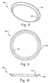
- FIGS. 8-10 are perspective, plan and cross-sectional views, respectively of an alternative compressible member.
- FIG. 1 Shown in FIG. 1 is a lamp assembly 100 that includes an inner assembly 102 having a light source 104 and electronics member or board, often referred to as a printed circuit board (PCB) 106 , and a holder 108 that interconnects the light source and the electronics board so that the inner assembly can be handled as a sub-assembly (although it will be appreciated that the inner assembly can also refer to the holder combined with the CFL light source without the electronics board).
- Enclosing the inner assembly is an outer envelope or bulb 120 which is preferably a light transmissive material such as glass.
- the outer envelope encloses an inner cavity dimensioned to receive the inner assembly therein.
- the outer envelope adopts the general conformation of an A-line lamp that has an enlarged generally spherical portion 122 at one end and a flare or neck portion 124 at the other end interconnected with the spherical portion by tapering region 126 .
- the outer envelope has a generally constant wall thickness that terminates in an opening at a first end 128 disposed adjacent a conventional electrically conductive base 130 , shown here as an externally threaded, Edison style base 130 .
- the threaded base is separated from an end contact 132 by an insulating material 134 .
- the base, and particularly the contact 132 and threaded region 130 thereof, are received in an associated lamp socket (not shown) to establish electrical and mechanical connection of the lamp assembly.
- other lamp bases such as conventional plug-in type connections that establish mechanical and electrical connection between the lamp assembly and an associated electrical socket can be used without departing from the scope and intent of the present disclosure.
- FIG. 2 more particularly illustrates the inner assembly 102 .
- the light source as illustrated here is a compact fluorescent lamp (CFL) 150 that includes first and second ends or legs 152 , 154 that extend generally parallel to one another and in a longitudinal direction that is generally parallel to a central lamp axis of the lamp assembly 100 .
- These legs 152 , 154 house electrodes at opposite ends of an elongated discharge path that includes each leg and an intermediate discharge path formed in an elongated tube formed here into a helical or spiral lamp arrangement 156 .
- the CFL legs are received in the holder 108 .
- the holder includes a platform 160 that has first and second openings 162 , 164 that closely receive the legs 152 , 154 of the CFL, respectively. Insertion of the legs into the platform openings is limited by L-shaped stop members 170 , 172 . In this manner, the legs of the CFL light source are located at a desired position or location relative to the remainder of the light assembly, particularly locating the legs adjacent the electronics board.
- the platform further includes an outer tapered perimeter 176 that substantially conforms to the tapered region 126 of the outer envelope. Disposed adjacent the tapered perimeter 176 is a shoulder 178 that receives a compressible or resilient ring, also referred to as a sealing O-ring 180 , that slidably and sealingly engages with the inner surface of the tapering region 126 of the outer envelope.
- the tapered perimeter and compressible O-ring provides for desired positioning and location of the inner assembly 102 within the outer envelope.
- the holder is formed of a heat-resistant material such as plastic and has sufficient rigidity and strength to provide a stable mounting of the CFL within the outer envelope. Further, the holder includes a passage 182 ( FIG.
- the passage 182 is provided to supply pressurized fluid, such as air, during a re-sealing process of the outer envelope which will be more particularly described below.
- the legs preferably have retaining shoulders 190 ( FIG. 4 ) dimensioned for snap-fit engagement with the electronics board 106 via legs 200 having similar retaining shoulders 202 on the electronics board that cooperate with the retaining shoulders 190 .
- the guide legs 188 aid in directing and aligning the inner assembly as the inner assembly is directed toward the neck portion of the outer envelope.
- extensions or support members 192 each have a channel 194 that engages a peripheral edge of the vertical PCB portion.
- the electronics board also includes a disk or platform 204 that includes a slot 206 to receive a vertically extending portion of the PCB which carries various electrical components 210 .
- the component is merely illustrative of one electrical component that may be disposed on the electronics board, and should not be intended to limit the construction.
- other electrical components 212 may be disposed on an upper surface of the platform 204 to allow ease of connection with the legs 152 , 154 of the CFL source.
- the inner assembly 102 may be pre-assembled as a sub-assembly.
- the diameter of the CFL source 150 is larger than the diameter or transverse dimension of the neck portion 124 of the outer envelope.
- the inner assembly 102 is inserted by directing the electronics board end initially inward into the lower portion 120 b of the outer envelope.
- the outer envelope is re-sealed along the plane 220 to define a one-piece outer envelope again.
- FIGS. 8-10 show an alternative compressible member 400 that has a tapered conformation that generally conforms to a portion of the tapered surface of the holder.
- the compressible member 400 includes an enlarged ring portion 402 received in an associated groove 404 in the perimeter of the holder, as well as a larger diameter, taper portion 406 that conforms and overlies the tapered surface of the holder.
- enlarged portion 402 serves as the equivalent of a compressible O-ring and assures sufficient material to effect a seal between the upper and lower surfaces of the holder.
- the tapered portion 406 overlies the tapered perimeter of the holder and is thus situated between the holder and the inner surface of the outer envelope. Again, this conforms the inner assembly to potential irregularities in the manufacture of the outer envelope and further enhances the prospects of a seal between the holder and the inner surface of the envelope.
- this disclosure provides a specially formed component, i.e., the holder, for self-ballasted CFLs having an outer envelope or bulb that holds fluorescent tubes (CFL) and a printed circuit board or ballast circuitry and fixes the CFL to an elongated part of the outer envelope.
- the holder serves a shielding function as well.
- the holder shields or helps to prevent the PCB and the ballast components from overheating during the cutting and sealing process of the outer bulb, as well as during normal operation of the lamp.
- the holder includes a rubber or silicon O-ring, or alternatively an adhesive material, for improving insulation and providing greater flexibility during fixing of the inner assembly to the outer envelope.
- the holder preferably has a specially formed rail part that holds and fixes the vertically oriented PCB.
- the rail preferably includes at least three (3) legs that are circumferentially spaced and help position the entire inner assembly into the outer envelope.
- the holder includes a special cylindrical portion having a passage through which air can be blown during the sealing process.
- the material of the holder can be varied, such as a plastic, silicone, or other materials that do not conduct heat and are able to withstand temperatures that occur during processing or assembly, as well as lamp operation.
- the holder advantageously provides or serves three different functions, namely, wire lamp or CFL positioning, fixing or location of the PCB, and thermal insulation.
- the exhaust tube is placed in a location where the temperature is lower than the temperature at the lamp. This results in an improved mercury vapor pressure.
- the passage provided through the holder insures the ability to provide an over-pressure during the sealing process of the outer envelope and for a better sealing quality. The passage aids in balancing the pressure between the spaces located above and below the holder. This disclosure removes the need for an intermediate collar between the outer envelope and the base, fixes the ballast, and simplifies assembly and cost.
Landscapes
- Engineering & Computer Science (AREA)
- Manufacturing & Machinery (AREA)
- Vessels And Coating Films For Discharge Lamps (AREA)
- Arrangement Of Elements, Cooling, Sealing, Or The Like Of Lighting Devices (AREA)
Abstract
Description
Claims (18)
Priority Applications (5)
| Application Number | Priority Date | Filing Date | Title |
|---|---|---|---|
| US12/181,414 US8072131B2 (en) | 2008-07-29 | 2008-07-29 | Holder for integral compact fluorescent lamp with outer bulb |
| CN2009801307565A CN102113086B (en) | 2008-07-29 | 2009-07-07 | Holder for integral compact fluorescent lamp with outer bulb |
| PCT/US2009/049779 WO2010014357A2 (en) | 2008-07-29 | 2009-07-07 | Holder for integral compact fluorescent lamp with outer bulb |
| KR1020117004069A KR20110048526A (en) | 2008-07-29 | 2009-07-07 | Holder for integrated compact fluorescent lamp with outer bulb |
| EP09790103A EP2308078A2 (en) | 2008-07-29 | 2009-07-07 | Holder for integral compact fluorescent lamp with outer bulb |
Applications Claiming Priority (1)
| Application Number | Priority Date | Filing Date | Title |
|---|---|---|---|
| US12/181,414 US8072131B2 (en) | 2008-07-29 | 2008-07-29 | Holder for integral compact fluorescent lamp with outer bulb |
Publications (2)
| Publication Number | Publication Date |
|---|---|
| US20100181911A1 US20100181911A1 (en) | 2010-07-22 |
| US8072131B2 true US8072131B2 (en) | 2011-12-06 |
Family
ID=40941900
Family Applications (1)
| Application Number | Title | Priority Date | Filing Date |
|---|---|---|---|
| US12/181,414 Expired - Fee Related US8072131B2 (en) | 2008-07-29 | 2008-07-29 | Holder for integral compact fluorescent lamp with outer bulb |
Country Status (5)
| Country | Link |
|---|---|
| US (1) | US8072131B2 (en) |
| EP (1) | EP2308078A2 (en) |
| KR (1) | KR20110048526A (en) |
| CN (1) | CN102113086B (en) |
| WO (1) | WO2010014357A2 (en) |
Families Citing this family (6)
| Publication number | Priority date | Publication date | Assignee | Title |
|---|---|---|---|---|
| US8845133B2 (en) * | 2011-07-27 | 2014-09-30 | General Electric Company | Thermal barrier and parts fixing in compact fluorescent lamps |
| US8915623B1 (en) * | 2012-02-01 | 2014-12-23 | St. Albert Innovations, LLC | Cover for a light bulb |
| KR101365633B1 (en) * | 2012-02-10 | 2014-02-24 | 강성석 | Discharge lamp |
| WO2015046890A1 (en) * | 2013-09-24 | 2015-04-02 | 강성진 | Discharge lamp |
| WO2015046891A1 (en) * | 2013-09-24 | 2015-04-02 | 강성진 | Discharge lamp comprising envelope |
| KR102428805B1 (en) * | 2020-04-02 | 2022-08-04 | 김경만 | Lighting frame |
Citations (8)
| Publication number | Priority date | Publication date | Assignee | Title |
|---|---|---|---|---|
| US5629586A (en) | 1994-06-30 | 1997-05-13 | Toshiba Lighting And Technology Corporation | Compact fluorescent lamp unit having first and second sealed end portions separated by a support member |
| US20020000770A1 (en) | 2000-06-30 | 2002-01-03 | Matsushita Electric Industrial Co., Ltd. | Fluorescent lamp and fluorescent lamp apparatus |
| US20020153838A1 (en) * | 2001-04-24 | 2002-10-24 | Johnston David W. | High pressure lamp bulb and method of induction sealing |
| US20030011327A1 (en) * | 2001-07-12 | 2003-01-16 | Dai Sung Moon | Ballast socket for compact fluorescent lamp |
| US20040121698A1 (en) | 2001-10-03 | 2004-06-24 | Kenji Itaya | Low-pressure mercury vapor discharge lamp with improved heat dissipation, and manufacturing method therefore |
| US20040232815A1 (en) | 2003-02-28 | 2004-11-25 | Yasushige Tomiyoshi | Compact self-ballasted fluorescent lamp with improved rising characteristics |
| US20050116604A1 (en) | 2003-12-02 | 2005-06-02 | Andrzej Bobel | Energy efficient compact fluorescent reflector lamp |
| US20080164803A1 (en) | 2005-02-04 | 2008-07-10 | Patent-Treuhand-Gesellschaft Fur Elektrische Gluhlampen Mbh | Uncemented Socketed Lamp |
Family Cites Families (1)
| Publication number | Priority date | Publication date | Assignee | Title |
|---|---|---|---|---|
| ES2338925T3 (en) * | 2003-07-02 | 2010-05-13 | S.C. JOHNSON & SON, INC. | LAMP AND BULB FOR LIGHTING AND ENVIRONMENTAL LIGHT. |
-
2008
- 2008-07-29 US US12/181,414 patent/US8072131B2/en not_active Expired - Fee Related
-
2009
- 2009-07-07 CN CN2009801307565A patent/CN102113086B/en not_active Expired - Fee Related
- 2009-07-07 WO PCT/US2009/049779 patent/WO2010014357A2/en not_active Ceased
- 2009-07-07 EP EP09790103A patent/EP2308078A2/en not_active Withdrawn
- 2009-07-07 KR KR1020117004069A patent/KR20110048526A/en not_active Ceased
Patent Citations (8)
| Publication number | Priority date | Publication date | Assignee | Title |
|---|---|---|---|---|
| US5629586A (en) | 1994-06-30 | 1997-05-13 | Toshiba Lighting And Technology Corporation | Compact fluorescent lamp unit having first and second sealed end portions separated by a support member |
| US20020000770A1 (en) | 2000-06-30 | 2002-01-03 | Matsushita Electric Industrial Co., Ltd. | Fluorescent lamp and fluorescent lamp apparatus |
| US20020153838A1 (en) * | 2001-04-24 | 2002-10-24 | Johnston David W. | High pressure lamp bulb and method of induction sealing |
| US20030011327A1 (en) * | 2001-07-12 | 2003-01-16 | Dai Sung Moon | Ballast socket for compact fluorescent lamp |
| US20040121698A1 (en) | 2001-10-03 | 2004-06-24 | Kenji Itaya | Low-pressure mercury vapor discharge lamp with improved heat dissipation, and manufacturing method therefore |
| US20040232815A1 (en) | 2003-02-28 | 2004-11-25 | Yasushige Tomiyoshi | Compact self-ballasted fluorescent lamp with improved rising characteristics |
| US20050116604A1 (en) | 2003-12-02 | 2005-06-02 | Andrzej Bobel | Energy efficient compact fluorescent reflector lamp |
| US20080164803A1 (en) | 2005-02-04 | 2008-07-10 | Patent-Treuhand-Gesellschaft Fur Elektrische Gluhlampen Mbh | Uncemented Socketed Lamp |
Non-Patent Citations (1)
| Title |
|---|
| PCT/US2009/049779 International Search Report. |
Also Published As
| Publication number | Publication date |
|---|---|
| CN102113086A (en) | 2011-06-29 |
| US20100181911A1 (en) | 2010-07-22 |
| EP2308078A2 (en) | 2011-04-13 |
| WO2010014357A2 (en) | 2010-02-04 |
| KR20110048526A (en) | 2011-05-11 |
| CN102113086B (en) | 2013-11-20 |
| WO2010014357A3 (en) | 2010-04-15 |
Similar Documents
| Publication | Publication Date | Title |
|---|---|---|
| US8072131B2 (en) | Holder for integral compact fluorescent lamp with outer bulb | |
| EP2122652B1 (en) | High pressure discharge lamp | |
| CN100578197C (en) | Light source device | |
| US7459856B1 (en) | Compact fluorescent lamp with outer envelope and method for manufacturing | |
| US6204602B1 (en) | Compact fluorescent lamp and ballast assembly with an air gap for thermal isolation | |
| JP2005123200A (en) | Light bulb shaped fluorescent lamp | |
| CN101911241A (en) | Compact fluorescent lamps with mechanical support and starting aid | |
| US6445131B1 (en) | Compact fluorescent lamp with built-in operating circuit | |
| CN100485858C (en) | compact discharge lamp | |
| EP1873443A1 (en) | Bulb type fluorescent lamp | |
| US8154186B2 (en) | Fixing mechanism for an inner assembly to outer bulb | |
| CN101120205B (en) | Light source device | |
| JP4045508B2 (en) | Light bulb type fluorescent lamp device | |
| KR100912760B1 (en) | Connector for ccfl, ccfl with connector and surface light source device | |
| KR200259298Y1 (en) | Bulb Type Fluorescent Lamp Provide With Ballast Stabilizer Cooling Means | |
| US20020145374A1 (en) | Two-piece base for lamp | |
| JP2003346505A (en) | Light bulb fluorescent lamps and lighting equipment | |
| JP2003168302A (en) | Bulb-type fluorescent lamp | |
| JPH0997589A (en) | Light bulb type fluorescent lamp device and lighting device | |
| JP2008047542A (en) | Fluorescent lamp device | |
| JP2010205727A (en) | Lamp with outer seal, and method of manufacturing the same |
Legal Events
| Date | Code | Title | Description |
|---|---|---|---|
| AS | Assignment |
Owner name: GE HUNGARY ZRT., HUNGARY Free format text: ASSIGNMENT OF ASSIGNORS INTEREST;ASSIGNORS:FULOP, JOZSEF;TALOSI, KAROLY;SCHMIDT, GABOR;AND OTHERS;REEL/FRAME:022721/0548 Effective date: 20090209 |
|
| AS | Assignment |
Owner name: GENERAL ELECTRIC COMPANY, NEW YORK Free format text: ASSIGNMENT OF ASSIGNORS INTEREST;ASSIGNOR:GE HUNGARY ZRT;REEL/FRAME:022786/0780 Effective date: 20090209 |
|
| FEPP | Fee payment procedure |
Free format text: PAYOR NUMBER ASSIGNED (ORIGINAL EVENT CODE: ASPN); ENTITY STATUS OF PATENT OWNER: LARGE ENTITY |
|
| STCF | Information on status: patent grant |
Free format text: PATENTED CASE |
|
| FPAY | Fee payment |
Year of fee payment: 4 |
|
| FEPP | Fee payment procedure |
Free format text: MAINTENANCE FEE REMINDER MAILED (ORIGINAL EVENT CODE: REM.); ENTITY STATUS OF PATENT OWNER: LARGE ENTITY |
|
| LAPS | Lapse for failure to pay maintenance fees |
Free format text: PATENT EXPIRED FOR FAILURE TO PAY MAINTENANCE FEES (ORIGINAL EVENT CODE: EXP.); ENTITY STATUS OF PATENT OWNER: LARGE ENTITY |
|
| STCH | Information on status: patent discontinuation |
Free format text: PATENT EXPIRED DUE TO NONPAYMENT OF MAINTENANCE FEES UNDER 37 CFR 1.362 |
|
| FP | Lapsed due to failure to pay maintenance fee |
Effective date: 20191206 |