US8071256B2 - Electrochemical energy generating apparatus and method for driving the apparatus - Google Patents
Electrochemical energy generating apparatus and method for driving the apparatus Download PDFInfo
- Publication number
- US8071256B2 US8071256B2 US11/578,762 US57876205A US8071256B2 US 8071256 B2 US8071256 B2 US 8071256B2 US 57876205 A US57876205 A US 57876205A US 8071256 B2 US8071256 B2 US 8071256B2
- Authority
- US
- United States
- Prior art keywords
- generation efficiency
- electrochemical
- electrochemical energy
- electrochemical device
- energy generation
- Prior art date
- Legal status (The legal status is an assumption and is not a legal conclusion. Google has not performed a legal analysis and makes no representation as to the accuracy of the status listed.)
- Expired - Fee Related, expires
Links
Images


Classifications
-
- H—ELECTRICITY
- H01—ELECTRIC ELEMENTS
- H01M—PROCESSES OR MEANS, e.g. BATTERIES, FOR THE DIRECT CONVERSION OF CHEMICAL ENERGY INTO ELECTRICAL ENERGY
- H01M8/00—Fuel cells; Manufacture thereof
- H01M8/04—Auxiliary arrangements, e.g. for control of pressure or for circulation of fluids
- H01M8/04298—Processes for controlling fuel cells or fuel cell systems
- H01M8/04313—Processes for controlling fuel cells or fuel cell systems characterised by the detection or assessment of variables; characterised by the detection or assessment of failure or abnormal function
- H01M8/04537—Electric variables
- H01M8/04544—Voltage
- H01M8/04559—Voltage of fuel cell stacks
-
- H—ELECTRICITY
- H01—ELECTRIC ELEMENTS
- H01M—PROCESSES OR MEANS, e.g. BATTERIES, FOR THE DIRECT CONVERSION OF CHEMICAL ENERGY INTO ELECTRICAL ENERGY
- H01M8/00—Fuel cells; Manufacture thereof
- H01M8/04—Auxiliary arrangements, e.g. for control of pressure or for circulation of fluids
- H01M8/04298—Processes for controlling fuel cells or fuel cell systems
- H01M8/04313—Processes for controlling fuel cells or fuel cell systems characterised by the detection or assessment of variables; characterised by the detection or assessment of failure or abnormal function
- H01M8/0444—Concentration; Density
- H01M8/04447—Concentration; Density of anode reactants at the inlet or inside the fuel cell
-
- H—ELECTRICITY
- H01—ELECTRIC ELEMENTS
- H01M—PROCESSES OR MEANS, e.g. BATTERIES, FOR THE DIRECT CONVERSION OF CHEMICAL ENERGY INTO ELECTRICAL ENERGY
- H01M8/00—Fuel cells; Manufacture thereof
- H01M8/04—Auxiliary arrangements, e.g. for control of pressure or for circulation of fluids
- H01M8/04298—Processes for controlling fuel cells or fuel cell systems
- H01M8/04313—Processes for controlling fuel cells or fuel cell systems characterised by the detection or assessment of variables; characterised by the detection or assessment of failure or abnormal function
- H01M8/0444—Concentration; Density
- H01M8/04462—Concentration; Density of anode exhausts
-
- H—ELECTRICITY
- H01—ELECTRIC ELEMENTS
- H01M—PROCESSES OR MEANS, e.g. BATTERIES, FOR THE DIRECT CONVERSION OF CHEMICAL ENERGY INTO ELECTRICAL ENERGY
- H01M8/00—Fuel cells; Manufacture thereof
- H01M8/04—Auxiliary arrangements, e.g. for control of pressure or for circulation of fluids
- H01M8/04298—Processes for controlling fuel cells or fuel cell systems
- H01M8/04313—Processes for controlling fuel cells or fuel cell systems characterised by the detection or assessment of variables; characterised by the detection or assessment of failure or abnormal function
- H01M8/04537—Electric variables
- H01M8/04574—Current
- H01M8/04589—Current of fuel cell stacks
-
- H—ELECTRICITY
- H01—ELECTRIC ELEMENTS
- H01M—PROCESSES OR MEANS, e.g. BATTERIES, FOR THE DIRECT CONVERSION OF CHEMICAL ENERGY INTO ELECTRICAL ENERGY
- H01M8/00—Fuel cells; Manufacture thereof
- H01M8/04—Auxiliary arrangements, e.g. for control of pressure or for circulation of fluids
- H01M8/04298—Processes for controlling fuel cells or fuel cell systems
- H01M8/04694—Processes for controlling fuel cells or fuel cell systems characterised by variables to be controlled
- H01M8/04701—Temperature
-
- H—ELECTRICITY
- H01—ELECTRIC ELEMENTS
- H01M—PROCESSES OR MEANS, e.g. BATTERIES, FOR THE DIRECT CONVERSION OF CHEMICAL ENERGY INTO ELECTRICAL ENERGY
- H01M8/00—Fuel cells; Manufacture thereof
- H01M8/04—Auxiliary arrangements, e.g. for control of pressure or for circulation of fluids
- H01M8/04298—Processes for controlling fuel cells or fuel cell systems
- H01M8/04694—Processes for controlling fuel cells or fuel cell systems characterised by variables to be controlled
- H01M8/04746—Pressure; Flow
- H01M8/04753—Pressure; Flow of fuel cell reactants
-
- H—ELECTRICITY
- H01—ELECTRIC ELEMENTS
- H01M—PROCESSES OR MEANS, e.g. BATTERIES, FOR THE DIRECT CONVERSION OF CHEMICAL ENERGY INTO ELECTRICAL ENERGY
- H01M8/00—Fuel cells; Manufacture thereof
- H01M8/04—Auxiliary arrangements, e.g. for control of pressure or for circulation of fluids
- H01M8/04298—Processes for controlling fuel cells or fuel cell systems
- H01M8/04694—Processes for controlling fuel cells or fuel cell systems characterised by variables to be controlled
- H01M8/04791—Concentration; Density
- H01M8/04798—Concentration; Density of fuel cell reactants
-
- H—ELECTRICITY
- H01—ELECTRIC ELEMENTS
- H01M—PROCESSES OR MEANS, e.g. BATTERIES, FOR THE DIRECT CONVERSION OF CHEMICAL ENERGY INTO ELECTRICAL ENERGY
- H01M8/00—Fuel cells; Manufacture thereof
- H01M8/10—Fuel cells with solid electrolytes
- H01M8/1009—Fuel cells with solid electrolytes with one of the reactants being liquid, solid or liquid-charged
- H01M8/1011—Direct alcohol fuel cells [DAFC], e.g. direct methanol fuel cells [DMFC]
-
- H—ELECTRICITY
- H01—ELECTRIC ELEMENTS
- H01M—PROCESSES OR MEANS, e.g. BATTERIES, FOR THE DIRECT CONVERSION OF CHEMICAL ENERGY INTO ELECTRICAL ENERGY
- H01M8/00—Fuel cells; Manufacture thereof
- H01M8/10—Fuel cells with solid electrolytes
- H01M2008/1095—Fuel cells with polymeric electrolytes
-
- H—ELECTRICITY
- H01—ELECTRIC ELEMENTS
- H01M—PROCESSES OR MEANS, e.g. BATTERIES, FOR THE DIRECT CONVERSION OF CHEMICAL ENERGY INTO ELECTRICAL ENERGY
- H01M2250/00—Fuel cells for particular applications; Specific features of fuel cell system
- H01M2250/20—Fuel cells in motive systems, e.g. vehicle, ship, plane
-
- H—ELECTRICITY
- H01—ELECTRIC ELEMENTS
- H01M—PROCESSES OR MEANS, e.g. BATTERIES, FOR THE DIRECT CONVERSION OF CHEMICAL ENERGY INTO ELECTRICAL ENERGY
- H01M2250/00—Fuel cells for particular applications; Specific features of fuel cell system
- H01M2250/30—Fuel cells in portable systems, e.g. mobile phone, laptop
-
- Y—GENERAL TAGGING OF NEW TECHNOLOGICAL DEVELOPMENTS; GENERAL TAGGING OF CROSS-SECTIONAL TECHNOLOGIES SPANNING OVER SEVERAL SECTIONS OF THE IPC; TECHNICAL SUBJECTS COVERED BY FORMER USPC CROSS-REFERENCE ART COLLECTIONS [XRACs] AND DIGESTS
- Y02—TECHNOLOGIES OR APPLICATIONS FOR MITIGATION OR ADAPTATION AGAINST CLIMATE CHANGE
- Y02B—CLIMATE CHANGE MITIGATION TECHNOLOGIES RELATED TO BUILDINGS, e.g. HOUSING, HOUSE APPLIANCES OR RELATED END-USER APPLICATIONS
- Y02B90/00—Enabling technologies or technologies with a potential or indirect contribution to GHG emissions mitigation
- Y02B90/10—Applications of fuel cells in buildings
-
- Y—GENERAL TAGGING OF NEW TECHNOLOGICAL DEVELOPMENTS; GENERAL TAGGING OF CROSS-SECTIONAL TECHNOLOGIES SPANNING OVER SEVERAL SECTIONS OF THE IPC; TECHNICAL SUBJECTS COVERED BY FORMER USPC CROSS-REFERENCE ART COLLECTIONS [XRACs] AND DIGESTS
- Y02—TECHNOLOGIES OR APPLICATIONS FOR MITIGATION OR ADAPTATION AGAINST CLIMATE CHANGE
- Y02E—REDUCTION OF GREENHOUSE GAS [GHG] EMISSIONS, RELATED TO ENERGY GENERATION, TRANSMISSION OR DISTRIBUTION
- Y02E60/00—Enabling technologies; Technologies with a potential or indirect contribution to GHG emissions mitigation
- Y02E60/30—Hydrogen technology
- Y02E60/50—Fuel cells
-
- Y—GENERAL TAGGING OF NEW TECHNOLOGICAL DEVELOPMENTS; GENERAL TAGGING OF CROSS-SECTIONAL TECHNOLOGIES SPANNING OVER SEVERAL SECTIONS OF THE IPC; TECHNICAL SUBJECTS COVERED BY FORMER USPC CROSS-REFERENCE ART COLLECTIONS [XRACs] AND DIGESTS
- Y02—TECHNOLOGIES OR APPLICATIONS FOR MITIGATION OR ADAPTATION AGAINST CLIMATE CHANGE
- Y02T—CLIMATE CHANGE MITIGATION TECHNOLOGIES RELATED TO TRANSPORTATION
- Y02T90/00—Enabling technologies or technologies with a potential or indirect contribution to GHG emissions mitigation
- Y02T90/40—Application of hydrogen technology to transportation, e.g. using fuel cells
Definitions
- the present invention relates to an electrochemical energy generating apparatus and a method for driving the apparatus.
- Lithium ion secondary batteries have two advantageous properties of high energy density and high power density and hence are at a higher level of perfection, and widely used as power sources for mobile devices.
- the mobile devices have higher performance and are likely to have increased power consumption, and therefore a lithium ion secondary battery having further improved energy density and power density is demanded.
- the fuel cell includes an anode electrode and a cathode electrode, and a fuel is supplied to the anode electrode side, and air or oxygen is fed to the cathode electrode side.
- the fuel is supplied to cause a redox reaction, and electric energy can be taken from the chemical energy of the fuel.
- a number of types of fuel cells are present in the world, and, according to the electrolyte membranes used in the fuel cells, they are classified into an alkali system (AFC), a phosphoric acid system (PAFC), a melt carbonate system (MCFC), a solid oxide system (SOFC), and a solid polymer system.
- AFC alkali system
- PAFC phosphoric acid system
- MCFC melt carbonate system
- SOFC solid oxide system
- DMFC direct methanol fuel cell
- the DMFC uses a methanol solution as a fuel having a theoretical energy density of 4.8 kW/l, which is ten times or more the energy density of the lithium ion secondary battery.
- the fuel cell using methanol as a fuel achieves an energy density higher than that of the lithium ion secondary battery.
- the DMFC has advantages in that it does not need a reformer for taking hydrogen from a raw material and hence can be relatively simply designed, and that the DMFC normally operates at a low temperature of 30 to 130° C., as compared to other fuel cells.
- an aqueous methanol solution As a fuel for the DMFC, an aqueous methanol solution is used, and the aqueous methanol solution is supplied to the anode electrode side.
- the aqueous methanol solution advances an oxidation reaction at the catalyst layer on the anode electrode side to form carbon dioxide.
- Protons generated in this instance travel through an electrolyte membrane separating the anode electrode and the cathode electrode toward the cathode electrode where the protons react with oxygen to form water.
- the reactions proceeding on the anode electrode side and the cathode electrode side and the DMFC as a whole are represented by the following formulae.
- Anode electrode CH 3 OH+H 2 O ⁇ CO 2 +6 e ⁇ +6H + Cathode electrode: 3/2O 2 +6 e ⁇ +6H + ⁇ 3H 2 O DMFC as a whole: CH 3 OH+3/2O 2 ⁇ CO 2 +2H 2 O
- a theoretical voltage generated by the above reactions is 1.23 V, but an actual voltage during the power generation is about 0.6 V or less.
- the reason the actual voltage is lower than the theoretical voltage resides in voltage depression caused due to the internal resistances of the DMFC, and there are present internal resistances inside the DMFC, such as a resistance caused due to the reaction proceeding at each electrode, a resistance caused due to the movement of a substance, a resistance caused when protons travel through the electrolyte membrane, and a contact resistance.
- Energy which can be taken from methanol is represented by a product of a voltage during the power generation and an amount of electrons flowing the circuit by the redox reaction of methanol, i.e., an output current, and, the lower the voltage during the power generation, the smaller the energy which can be taken from methanol.
- the total amount of the electrons flowing the circuit by the redox reaction of methanol is proportional to the amount of the methanol in the fuel if the below-mentioned methanol crossover is not caused.
- the DMFC has a problem of methanol crossover.
- the methanol crossover is a phenomenon that occurs due to both diffusion caused by the methanol concentration gradient between the anode electrode side and the cathode electrode side, and electro-osmosis such that methanol leaks from the anode electrode side to the cathode electrode side in association with water moving due to the travel of protons.
- Methanol penetrates the electrolyte membrane and goes from the anode electrode side to the cathode electrode side, and the methanol undergoes an oxidation reaction at the catalyst on the cathode electrode side, so that a counter-electromotive force is generated on the cathode electrode side, thus lowering the voltage. Further, this problem leads to another one in that the methanol is not used in the power generation but consumed on the cathode electrode side.
- the DMFC has two problems of the lowering of the voltage due to the internal resistance and methanol crossover and the fuel consumption by methanol crossover, and these problems are factors in lowering the power generation efficiency of the DMFC.
- a method for preventing the methanol crossover a method in which the all methanol supplied is used up on the anode electrode side is considered.
- the increase of the amount of the catalyst carried can improve the catalytic activity to some extent, but the increase of the catalyst causes the internal resistance to be larger, leading to a problem in that the voltage is lowered.
- a polyperfluoroalkylsulfonic acid membrane ⁇ e.g., Nafion (registered trademark) membrane ⁇ which is generally used as an electrolyte membrane for DMFC, advantageously has high Proton conductivity, but it also has high permeability to methanol.
- An optimal catalyst has not yet been found as mentioned above, and similarly an optimal electrolyte membrane has not yet been found.
- an article: “Journal of Power Sources, 112, (2002) 339-352” has a description showing that the power density and power generation efficiency of a DMFC vary mainly depending on the temperature, the flow rate of the fuel supplied, and the fuel concentration, and a description about the properties of the fuel cell as the above operational environments are changed.
- the article has a description that, in the power generation by the fuel cell under the above operating conditions, the output is high, but the methanol crossover is increased, and hence the power generation efficiency becomes poor. Further, the article also has a description that a power generation efficiency required for obtaining the same output markedly varies depending on the operating conditions.
- a method is considered in which the properties of the fuel cell are measured while finely changing parameters, such as the temperature, the flow rate of the fuel supplied, and the fuel concentration, and the operating conditions under which a high power generation efficiency is obtained are preliminarily determined to prepare a database, and the operation of the fuel cell is controlled based on the database.
- the above-mentioned method in which a database is prepared and the operation is controlled based on the database has a disadvantage in that there are too many parameters that affect the power generation efficiency of the DMFC and therefore the measurement requires a prolonged time.
- the method also has a disadvantage in that the measured data is of an enormous amount and the control program inevitably has an increased size.
- the fuel cell changes in internal properties due to CO poisoning occurring at the anode electrode, flooding occurring at the cathode electrode, and deterioration of the electrolyte membrane, and, in the method of the Patent document 1 above, the operating conditions of the fuel cell are determined based on the data preliminarily measured or mathematical formula prepared from the physical model, and hence it is difficult to allow the DMFC to generate power under the operating conditions in which the power generation efficiency is constantly high in an environment for practical use such that the DMFC is used for a long time.
- the change of the internal properties of the fuel cell is not taken into consideration, and the power generation efficiency as calculated by a mathematical formula is not always obtained in actually driving the fuel cell.
- the power generation using the DMFC is supposed to continue for several months to one year or longer, and the internal properties of the fuel cell inevitably change during the power generation. In other words, the operating conditions under which the power generation efficiency of the DMFC is the maximum continuously change.
- the power generation efficiency of the DMFC cannot be constantly maximized, making it difficult to efficiently take energy from methanol. Even when using methanol having a high energy density, the advantageous property of methanol cannot be fully utilized. For this reason, the DMFC using the conventional control technique can achieve only an energy density equivalent to or less than that of the lithium ion secondary battery.
- the present invention has been achieved for solving the above problems, and an object is to provide an electrochemical energy generating apparatus, which can constantly achieve high energy density according to a change of the internal properties of an electrochemical device, such as a fuel cell, and a method for driving the apparatus.
- the present invention is directed to an electrochemical energy generating apparatus, which includes:
- a measurement section measuring an operational state of the electrochemical device
- control section connected to the measurement section and the regulation section, and controlling the operating conditions
- control section controls the regulation section based on a measurement obtained by the measurement section during the operation of the electrochemical device to regulate the operating conditions through the regulation section.
- the present invention is directed to a method for driving an electrochemical energy generating apparatus, wherein the method includes driving an electrochemical device using:
- control section connected to the measurement section and regulation section, and controlling the operating conditions
- measuring by the measurement section the operational state of the electrochemical device inputting a measurement obtained by the measurement section into the control section, and controlling by the control section the regulation section based on the measurement during the operation of the electrochemical device.
- FIG. 1 is a diagrammatic view showing the construction of the electrochemical energy generating apparatus according to an embodiment of the present invention.
- FIG. 2 is a diagrammatic cross-sectional view of a fuel cell constituting the electrochemical energy generating apparatus according to an embodiment of the present invention.
- FIGS. 3A and 3B are a flowchart of one example of the method for driving an electrochemical energy generating apparatus according to an embodiment of the present invention.
- FIGS. 4A and 4B are a flowchart of another example of the method for driving an electrochemical energy generating apparatus according to an embodiment of the present invention.
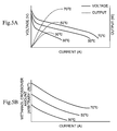
- FIGS. 5A and 5B are graphs showing the properties of a fuel cell.
- FIG. 5A is a graph showing the output current/output voltage properties and output current/output properties of the fuel cell.
- FIG. 5B is a graph showing the output current/methanol crossover properties.
- the measurement section includes current measuring means for measuring an output current of the electrochemical device, voltage measuring means for measuring an output voltage of the electrochemical device, and raw material concentration measuring means for measuring a concentration of a raw material discharged from the electrochemical device relative to a raw material supplied to the electrochemical device, wherein data obtained by the measuring means is input into the control section during the operation.
- control section calculates electrochemical energy generation efficiency from the data and controls the regulation section based on the calculated value.
- the regulation section includes at least one member selected from temperature regulating means for regulating a temperature of the electrochemical device, flow rate/pressure regulating means for regulating a flow rate or/and a pressure of a raw material supplied to the electrochemical device, flow rate/pressure regulating means for regulating a flow rate or/and a pressure of another raw material supplied to the electrochemical device, and concentration regulating means for regulating a concentration of a raw material supplied to the electrochemical device.
- the electrochemical device includes a Proton conducting material sandwiched between electrodes facing each other, and more specifically, is formed as a fuel cell.
- the steps of measuring and controlling be repeated (for example, at intervals of two minutes) during the operation of the electrochemical device.
- adjusting by the regulation section the operating conditions of the electrochemical device to those of a larger one of the second and third electrochemical energy generation efficiency at the time the larger one is obtained measuring by the measurement section the operational state of the electrochemical device, inputting the data obtained into the control section, and calculating by the control section a fourth electrochemical energy generation efficiency (e.g., power generation efficiency E 4 mentioned below); and
- adjusting by the regulation section the operating conditions of the electrochemical device to those of the larger one of the second and third electrochemical energy generation efficiency at the time the larger one is obtained measuring by the measurement section the operational state of the electrochemical device, inputting the data obtained into the control section, and calculating the control section a fourth electrochemical energy generation efficiency (e.g., power generation efficiency E 4 mentioned below);
- the electrochemical energy generation efficiency is actually measured while changing the operating conditions of the electrochemical device during the operation to find the optimal operating conditions, and the electrochemical device is operated under the found optimal operating conditions. Therefore, even when the electrochemical device changes in internal properties, the electrochemical energy generation efficiency can be constantly maximized in response to such a change.
- the electrochemical device is a fuel cell ⁇ e.g., direct methanol fuel cell (DMFC) ⁇ is described.
- DMFC direct methanol fuel cell
- the formula (1) below is a formula for calculating a fuel efficiency ⁇ fuel .
- I cell means a current flowing from the DMFC during the operation
- I cross-over means a current consumed due to the methanol crossover.
- ⁇ fuel I cell /( I cross-over +I cell ) (1)
- the formula (2) below is a formula for calculating a voltage efficiency ⁇ voltage , which can be determined by dividing a measured voltage V measured , which is measured during the operation of the DMFC, by a theoretical voltage V theoretical In the DMFC, the theoretical voltage V theoretical is 1.23 V.
- ⁇ voltage V measured /V theoretical (2)
- ⁇ total V measured /V theoretical ⁇ I cell /( I cross-over +I cell ) (3)
- ⁇ total is inversely proportional to (I cross-over +I cell ) and hence, when the (I cross-over +I cell ) value is minimum, the ⁇ total value is maximum. In other words, by minimizing the methanol crossover current and the current flowing the circuit, the power generation efficiency of the DMFC can be maximized.
- FIG. 5A is a graph showing the current/voltage properties and current/output properties as a temperature changes.
- the DMFCs operating at 30° C., 50° C., and 70° C. are compared, one operating at a higher temperature offers a higher voltage and a higher output.
- a DMFC operating at a higher temperature can offer a certain output with a low current flowing the circuit, as compared to a DMFC operating at a lower temperature. Accordingly, by operating the DMFC at a higher temperature, the I cell value in the formula (4) above can be reduced.
- I cross-over and I cell determining the power generation efficiency of the DMFC remarkably vary depending on a change in the operating conditions including temperature, and affect the power generation efficiency.
- a fuel cell has a temperature at which the power generation efficiency is the maximum.
- the temperature at which the power generation efficiency of a fuel cell is maximum depends on the internal properties of the fuel cell, and the internal properties of the fuel cell change with time and hence, the temperature at which the power generation efficiency of the fuel cell is maximum continuously changes as the fuel cell is used. Therefore, merely preliminarily measuring the temperature at which the power generation efficiency is the maximum is insufficient, and it is important to find the temperature at which the power generation efficiency is maximum during the power generation.
- temperature is mentioned as an example, but the above description is similarly applied to other operating conditions, for example, the flow rate of a fuel supplied, the flow rate of air supplied, the fuel concentration, or the like.
- any method may be used, but a method for directly measuring the I cross-over and a method for indirectly measuring the I cross-over are described below.
- a method for directly measuring the I cross-over is in which a methanol concentration is measured and a current consumed by methanol crossover is calculated using the measurement.
- a concentration of an aqueous methanol solution supplied to the fuel cell and a concentration of an aqueous methanol solution discharged from the fuel cell are measured, and, from a difference between the measurements, a methanol amount C total consumed by the fuel cell per second is calculated.
- a cell voltage V cell of the whole DMFC is represented by the formula (5) below.
- E cell represents an equilibrium voltage
- ⁇ an represents an activation overvoltage of the anode
- ⁇ cat represents an activation overvoltage of the cathode
- ⁇ ohmic represents a resistance overvoltage
- ⁇ cross-over represents a crossover overvoltage.
- V cell E cell ⁇ an ⁇ cat ⁇ ohmic ⁇ cross-over (5)
- the cell voltage of the DMFC in such a state that the power generation is stopped contains information only on the equilibrium voltage and crossover overvoltage.
- the equilibrium voltage is presumed to be constant, it is apparent that the cell voltage in such a state that the power generation is stopped is a function of the crossover overvoltage, i.e., crossover current.
- the relationship between the cell voltage and the crossover current in such a state that the power generation is stopped is preliminarily determined, and, during the power generation, the power generation is stopped for a short time, for example, for one second to measure a cell voltage, thus enabling an indirect measurement of a crossover current.
- the technique of the present invention can be applied to any fuels. Further, when the crossover current is satisfactorily small, the power generation efficiency may be calculated form only a measurement of the output current I cell from the fuel cell.
- FIG. 1 is a diagrammatic view of one example of the electrochemical energy generating apparatus of the present invention.
- An electrochemical energy generating apparatus 1 of the present invention includes a fuel cell ⁇ MEA (membrane electrode assembly) ⁇ 2 as the electrochemical device for generating electrochemical energy, the measurement section for measuring the operational state of the fuel cell 2 , the regulation section for regulating the operating conditions of the fuel cell 2 , and a control section 11 , connected to the measurement section and the regulation section, for controlling the operating conditions.
- the control section 11 controls the regulation section based on a measurement obtained by the measurement section during the operation of the fuel cell 2 to regulate the operating conditions through the regulation section.
- the measurement section includes current measuring means 12 for measuring an output current of the fuel cell 2 , voltage measuring means 13 for measuring an output voltage of the fuel cell 2 , and crossover raw material (fuel) concentration measuring means 14 for measuring a concentration of a fuel discharged from the fuel cell 2 relative to a fuel supplied to the fuel cell 2 , wherein data obtained by the measuring means is input into the control section 11 through a communication line 21 during the operation.
- the raw material concentration measuring means 14 for example, a methanol concentration sensor can be used.
- the control section 11 calculates an electrochemical energy generation efficiency (power generation efficiency) from the data and controls the regulation section based on the calculated value.
- the control section 11 can use a microcomputer or the like, and has a not shown calculation section for calculating a power generation efficiency from the measurement input by the measurement section, a not shown storage section (memory) for storing the measurement, power generation efficiency, and the like, a not shown comparing section for comparing data from the memory with each other, a not shown signal input/output section for inputting the data from the measurement section or outputting a signal for regulation to the regulation section, and the like.
- the data from the measurement section can be sent to the control section 11 through, for example, the communication line 21 indicated by a dotted line, and the output signal for the regulation section can be sent to the regulation section through a communication line 22 indicated by a dot-dash line.
- the regulation section includes at least one member selected from temperature regulating means 15 for regulating a temperature of the fuel cell 2 , flowrate/pressure regulating means 16 for regulating a flow rate or/and a pressure of a fuel supplied to the fuel cell 2 , flowrate/pressure regulating means 17 for regulating a flow rate or/and a pressure of another raw material (oxygen) supplied to the fuel cell 2 , and concentration regulating means 18 for regulating a concentration of a fuel supplied to the fuel cell 2 .
- the flow rate can be regulated by opening or closing a not shown regulating valve according to a signal from the control section 11 .
- the concentration regulating means 18 has a not shown means for controlling the amount of a raw material, such as methanol, or water added.
- a raw material such as methanol
- the flow rate of the liquid raw material may be regulated by the flow rate/pressure regulating means 16
- gas such as hydrogen gas
- the pressure of the gas may be regulated by the flow rate/pressure regulating means 16 .
- An external circuit 19 indicates a mobile device ⁇ such as a portable telephone or a PDA (personal digital assistant) ⁇ , and operates using energy generated by the fuel cell 2 .
- the fuel cell 2 includes, as shown in FIG. 2 , an MEA (membrane electrode assembly) 8 which includes a Proton conducting material 3 as a center sandwiched between electrode substrates (an anode current collector 6 and a cathode current collector 7 ) respectively having catalyst layers (an anode catalyst layer 4 and a cathode catalyst layer 5 ), and separators 70 having the MEA 8 disposed therebetween.
- an MEA membrane electrode assembly
- a Proton conducting material 3 used in the MEA 8 a perfluorosulfonic acid resin ⁇ e.g., Nafion (registered trademark), manufactured and sold by Du Pont Co., Ltd. ⁇ or the like can be used.
- Each of the electrode substrates 6 , 7 is comprised of carbon cloth, carbon paper, or carbon sheet treated with PTFE (polytetrafluoroethylene) for water-repellency.
- PTFE polytetrafluoroethylene
- palladium (Pd), platinum (Pt), iridium (Ir), rhodium (Rh), ruthenium (Ru), or the like can be used.
- a fuel 9 for the fuel cell hydrogen, an alcohol, such as methanol, a hydrocarbon, or the like can be used.
- the fuel 9 e.g., an aqueous methanol solution is supplied to the anode electrode 4 side and a catalytic reaction causes the fuel to generate protons, and the protons travel through the Proton conducting material 3 toward the cathode electrode 5 where the protons react with oxygen (air) 10 supplied to the cathode electrode 5 , thus producing a desired electromotive force.
- a catalytic reaction causes the fuel to generate protons, and the protons travel through the Proton conducting material 3 toward the cathode electrode 5 where the protons react with oxygen (air) 10 supplied to the cathode electrode 5 , thus producing a desired electromotive force.
- the fuel 9 e.g., an aqueous methanol solution is stored in a tank 20 before supplied to the fuel cell 2 , and regulated by the concentration regulating means 18 so that it has a desired concentration, and then supplied to the anode electrode 4 side in the fuel cell 2 .
- the power generation efficiency of the fuel cell 2 as the electrochemical device depends on the temperature, the flow rate of the fuel supplied, the fuel concentration, the pressure of the air (oxygen) supplied, and the like, and an example of a method for maximizing the power generation efficiency by regulating the temperature is described with reference to FIGS. 3A and 3B and an example of a method for maximizing the power generation efficiency by regulating the flow rate of a fuel (e.g., aqueous methanol solution) supplied to the fuel cell 2 is described with reference to FIGS. 4A and 4B .
- a fuel e.g., aqueous methanol solution
- the temperature regulating means 15 first measures a temperature T of the electrochemical energy generating apparatus 1 of the present invention, and a measurement is sent to the control section 11 through the communication line 22 .
- the current measuring means 12 for measuring an output current of the fuel cell 2 measures an output current
- the raw material (fuel) concentration measuring means 14 for measuring a concentration of the fuel discharged from the fuel cell 2 relative to the fuel supplied to the fuel cell 2 measures a methanol crossover amount, i.e., a methanol crossover current, and these measurements are sent to the control section 11 through the communication line 21 .
- the measurements obtained in the step 24 are applied to the formula (4) above to calculate a power generation efficiency E 1 .
- the temperature regulating means 15 adjusts the temperature of the electrochemical energy generating apparatus 1 to a value (T+ ⁇ T) obtained by adding the temperature T measured in the step 23 and an arbitrary temperature ( ⁇ T) together.
- the current measuring means 12 measures an output current of the fuel cell and the raw material concentration measuring means 14 measures a methanol crossover amount, i.e., a methanol crossover current, and these measurements are sent to the control section 11 through the communication line 21 .
- the measurements obtained in the step 27 are applied to the formula (4) above to calculate a power generation efficiency E 2 .
- the temperature regulating means 15 adjusts the temperature of the electrochemical energy generating apparatus 1 to a value (T ⁇ T) obtained by subtracting an arbitrary temperature ( ⁇ T) from the temperature T measured in the step 23 .
- the current measuring means 12 measures an output current of the fuel cell and the raw material concentration measuring means 14 measures a methanol crossover amount, i.e., a methanol crossover current, and these measurements are sent to the control section 11 through the communication line 21 .
- the measurements obtained in the step 30 are applied to the formula (4) above to calculate a power generation efficiency E 3 .
- the thus calculated power generation efficiencies E 2 and E 3 are compared.
- the temperature of the electrochemical energy generating apparatus 1 is adjusted to a value (T+ ⁇ T) obtained by adding the temperature T measured in the step 23 and an arbitrary temperature ( ⁇ T) together.
- the temperature of the electrochemical energy generating apparatus 1 is adjusted to a value (T ⁇ T) obtained by subtracting an arbitrary temperature ( ⁇ T) from the temperature T measured in the step 23 .
- the current measuring means 12 measures an output current of the fuel cell and the raw material concentration measuring means 14 measures a methanol crossover amount, i.e., a methanol crossover current, and these measurements are sent to the control section 11 through the communication line 21 .
- the measurements obtained in the step 35 are applied to the formula (4) above to calculate a power generation efficiency E 4 .
- step 37 the power generation efficiency E 1 and the power generation efficiency E 4 are compared.
- the temperature T at which the power generation efficiency E 1 is determined is involved in the operating conditions for obtaining the maximum power generation efficiency, and hence, as shown in a step 38 , the control section 11 transmits an output signal for temperature regulation so that the temperature regulating means 15 adjusts the temperature of the electrochemical energy generating apparatus 1 to the temperature T, thus completing the adjustment and control (step 39 ).
- the temperature of the electrochemical energy generating apparatus 1 is further adjusted.
- the temperature of the electrochemical energy generating apparatus 1 is adjusted to a value (T+ ⁇ T) obtained by adding the temperature T measured in the step 23 and an arbitrary temperature ( ⁇ T) together
- the temperature is adjusted to a value (T+ ⁇ T+ ⁇ T) obtained by adding the temperature (T+ ⁇ T) and ⁇ T together.
- the current measuring means 12 measures an output current of the fuel cell and the raw material concentration measuring means 14 measures a methanol crossover amount, i.e., a methanol crossover current, and these measurements are sent to the control section 11 through the communication line 21 .
- the measurements obtained in the step 41 are applied to the formula (4) above to calculate a power generation efficiency E 5 .
- the power generation efficiency E 4 and the power generation efficiency E 5 are compared.
- the temperature (T+ ⁇ T) or (T ⁇ T) at which the power generation efficiency E 4 is determined is involved in the operating conditions for obtaining the maximum power generation efficiency, and hence, as shown in a step 44 , the control section 11 transmits an output signal for temperature regulation so that the temperature regulating means 15 adjusts the temperature of the electrochemical energy generating apparatus 1 to the temperature (T+ ⁇ T) or (T ⁇ T), thus completing the adjustment and control (step 45 ).
- the adjustment and control are not conducted only when the voltage, current, or the like changes but performed at predetermined intervals (e.g., at intervals of two minutes) as indicated by dotted lines in FIGS. 3A and 3B .
- the electrochemical device e.g., fuel cell
- the power generation efficiency can be constantly maximized according to the change.
- the power generation efficiency is actually measured while changing the operating conditions of the fuel cell 2 during the operation to find the optimal operating conditions, and the fuel cell 2 is operated under the found optimal operating conditions. Therefore, even when the fuel cell 2 changes in internal properties, the power generation efficiency can be constantly maximized according to the change, so that energy obtainable at the power generation efficiency can be always maximum, thus making it possible to extend the period of time during which the external circuit 19 , e.g., a mobile device can be used.
- the fuel flow rate/pressure regulating means 16 first measures a flow rate Q of the aqueous methanol solution supplied to the electrochemical energy generating apparatus 1 of the present invention, and a measurement is sent to the control section 11 through the communication line 22 .
- the current measuring means 12 for measuring an output current of the fuel cell 2 measures an output current and the raw material (fuel) concentration measuring means 14 for measuring a concentration of the fuel discharged from the fuel cell 2 relative to the fuel supplied to the fuel cell 2 measures a methanol crossover amount, i.e., a methanol crossover current, and these measurements are sent to the control section 11 through the communication line 21 .
- the measurements obtained in the step 47 are applied to the formula (4) above to calculate a power generation efficiency E 1 .
- the flow rate/pressure regulating means 16 adjusts the flow rate of the aqueous methanol solution supplied to a value (Q+ ⁇ Q) obtained by adding the flow rate Q measured in the step 46 and an arbitrary flow rate ( ⁇ Q) together.
- the current measuring means 12 measures an output current of the fuel cell and the raw material concentration measuring means 14 measures a methanol crossover amount, i.e., a methanol crossover current, and these measurements are sent to the control section 11 through the communication line 21 .
- the measurements obtained in the step 50 are applied to the formula (4) above to calculate a power generation efficiency E 2 .
- the flow rate/pressure regulating means 16 adjusts the flow rate of the aqueous methanol solution supplied to a value (Q ⁇ Q) obtained by subtracting an arbitrary flow rate ( ⁇ Q) from the flow rate Q measured in the step 46 .
- the current measuring means 12 measures an output current of the fuel cell and the raw material concentration measuring means 14 measures a methanol crossover amount, i.e., a methanol crossover current, and these measurements are sent to the control section 11 through the communication line 21 .
- the measurements obtained in the step 53 are applied to the formula (4) above to calculate a power generation efficiency E 3 .
- the thus calculated power generation efficiencies E 2 and E 3 are compared.
- the flow rate of the aqueous methanol solution supplied is adjusted to a value (Q+ ⁇ Q) obtained by adding the flow rate Q measured in the step 46 and an arbitrary flow rate ( ⁇ Q) together.
- the flow rate of the aqueous methanol solution supplied is adjusted to a value (Q ⁇ Q) obtained by subtracting an arbitrary flow rate ( ⁇ Q) from the flow rate Q measured in the step 46 .
- the current measuring means 12 measures an output current of the fuel cell and the raw material concentration measuring means 14 measures a methanol crossover amount, i.e., a methanol crossover current, and these measurements are sent to the control section 11 through the communication line 21 .
- the measurements obtained in the step 58 are applied to the formula (4) above to calculate a power generation efficiency E 4 .
- the power generation efficiency E 1 and the power generation efficiency E 4 are compared.
- the flow rate Q at which the power generation efficiency E 1 is determined is involved in the operating conditions for obtaining the maximum power generation efficiency, and hence, as shown in a step 61 , the control section 11 transmits an output signal for flow rate regulation so that the flowrate/pressure regulating means 16 adjusts the flow rate of the aqueous methanol solution supplied to the flow rate Q, thus completing the adjustment and control (step 62 ).
- the flow rate of the aqueous methanol solution supplied is further adjusted.
- the power generation efficiencies E 2 and E 3 were compared in the step 55 and consequently the procedure went to the step 56 where the flow rate of the aqueous methanol solution supplied was adjusted to a value (Q+ ⁇ Q) obtained by adding the flow rate Q measured in the step 46 and an arbitrary flow rate ( ⁇ Q) together, the flow rate is adjusted to a value (Q+ ⁇ Q+ ⁇ Q) obtained by adding the flow rate (Q+ ⁇ Q) and ⁇ Q together.
- the current measuring means 12 measures an output current of the fuel cell and the raw material concentration measuring means 14 measures a methanol crossover amount, i.e., a methanol crossover current, and these measurements are sent to the control section 11 through the communication line 21 .
- the measurements obtained in the step 64 are applied to the formula (4) above to calculate a power generation efficiency E 5 .
- the power generation efficiency E 4 and the power generation efficiency E 5 are compared.
- the flow rate (Q+ ⁇ Q) or (Q ⁇ Q) at which the power generation efficiency E 4 is determined is involved in the operating conditions for obtaining the maximum power generation efficiency, and hence, as shown in a step 67 , the control section 11 transmits an output signal for flow rate regulation so that the flow rate/pressure regulating means 16 adjusts the flow rate of the aqueous methanol solution supplied to the flow rate (Q+ ⁇ Q) or (Q ⁇ Q), thus completing the adjustment and control (step 68 ).
- the adjustment and control are not conducted only when the voltage, current, or the like changes but performed at predetermined intervals (e.g., at intervals of two minutes) as indicated by dotted lines in FIGS. 4A and 4B .
- the electrochemical device e.g., fuel cell
- the power generation efficiency can be constantly maximized according to the change.
- the power generation efficiency is actually measured while changing the operating conditions of the fuel cell 2 during the operation to find the optimal operating conditions, and the fuel cell 2 is operated under the found optimal operating conditions. Therefore, even when the fuel cell 2 changes in internal properties, the power generation efficiency can be constantly maximized according to the change, so that energy obtainable at the power generation efficiency can be always maximum, thus making it possible to extend the period of time during which the external circuit 19 , e.g., a mobile device can be used.
- the form, material, and the like of the electrochemical device can be appropriately selected.
- the arrangement or position of the control section, the measurement section, the regulation section, the electrochemical device, and others constituting the apparatus of the present invention there is no particular limitation.
- the power generation efficiency may be maximized by regulating the fuel concentration, the pressure of air (oxygen) supplied, or the like.
- the temperature, the raw material flow rate/pressure, the raw material concentration, and the another raw material flow rate/pressure may be controlled either independently or in communication with one another by the control section.
- the measurement section measures the operational state of the electrochemical device and a measurement obtained by the measurement section is input into the control section, and the control section controls the regulation section based on the measurement during the operation of the electrochemical device. Therefore, the electrochemical energy generation efficiency can be obtained as an actual measurement, and the operating conditions can be regulated according to a change of the internal properties of the electrochemical device, thus making it possible to obtain constantly high energy density.
Landscapes
- Life Sciences & Earth Sciences (AREA)
- Engineering & Computer Science (AREA)
- Manufacturing & Machinery (AREA)
- Sustainable Development (AREA)
- Sustainable Energy (AREA)
- Chemical & Material Sciences (AREA)
- Chemical Kinetics & Catalysis (AREA)
- Electrochemistry (AREA)
- General Chemical & Material Sciences (AREA)
- Fuel Cell (AREA)
Abstract
Description
Anode electrode: CH3OH+H2O→CO2+6e −+6H+
Cathode electrode: 3/2O2+6e −+6H+→3H2O
DMFC as a whole: CH3OH+3/2O2→CO2+2H2O
μfuel =I cell/(I cross-over +I cell) (1)
ηvoltage =V measured /V theoretical (2)
ηtotal =V measured /V theoretical ×I cell/(I cross-over +I cell) (3)
ηtotal =K/(I cross-over +I cell) (4)
V cell =E cell−ηan−ηcat−ηohmic−ηcross-over (5)
V cell =E cell−ηcross-over (6)
Claims (9)
Applications Claiming Priority (3)
| Application Number | Priority Date | Filing Date | Title |
|---|---|---|---|
| JP2004-144369 | 2004-05-14 | ||
| JP2004144369A JP4710245B2 (en) | 2004-05-14 | 2004-05-14 | Driving method of electrochemical energy generating device |
| PCT/JP2005/009110 WO2005112173A1 (en) | 2004-05-14 | 2005-05-12 | System for producing electrochemical energy and method for driving such system |
Publications (2)
| Publication Number | Publication Date |
|---|---|
| US20070292737A1 US20070292737A1 (en) | 2007-12-20 |
| US8071256B2 true US8071256B2 (en) | 2011-12-06 |
Family
ID=35394446
Family Applications (1)
| Application Number | Title | Priority Date | Filing Date |
|---|---|---|---|
| US11/578,762 Expired - Fee Related US8071256B2 (en) | 2004-05-14 | 2005-05-12 | Electrochemical energy generating apparatus and method for driving the apparatus |
Country Status (3)
| Country | Link |
|---|---|
| US (1) | US8071256B2 (en) |
| JP (1) | JP4710245B2 (en) |
| WO (1) | WO2005112173A1 (en) |
Families Citing this family (13)
| Publication number | Priority date | Publication date | Assignee | Title |
|---|---|---|---|---|
| JP2007066589A (en) * | 2005-08-30 | 2007-03-15 | Yokogawa Electric Corp | Fuel cell characteristic evaluation method and characteristic evaluation apparatus |
| JPWO2007110969A1 (en) * | 2006-03-28 | 2009-08-06 | 株式会社日立製作所 | Method and apparatus for measuring fuel cell crossover loss |
| JP5344218B2 (en) * | 2008-08-18 | 2013-11-20 | ソニー株式会社 | Fuel cell system and electronic device |
| CN102119460B (en) * | 2008-08-18 | 2014-05-14 | 索尼公司 | Fuel cell system and electronic device |
| JP2010113985A (en) * | 2008-11-07 | 2010-05-20 | Sony Corp | Fuel cell and oxygen electrode for use in the same, and electronic apparatus |
| US20100124683A1 (en) * | 2008-11-20 | 2010-05-20 | Mti Microfuel Cells Inc. | Heat spreader assembly for use with a direct oxidation fuel cell |
| US20110244351A1 (en) * | 2010-04-01 | 2011-10-06 | Jung-Kurn Park | Operating method of fuel cell system |
| JP6125750B2 (en) * | 2011-12-28 | 2017-05-10 | 学校法人幾徳学園 | Fuel cell power generation system and control method thereof |
| FR3041478A1 (en) | 2015-09-21 | 2017-03-24 | Commissariat Energie Atomique | DETERMINING A SPATIAL DISTRIBUTION OF THE PERMEABILITY OF AN ELECTROCHEMICAL CELL ELECTRODE |
| FR3041480A1 (en) * | 2015-09-21 | 2017-03-24 | Commissariat Energie Atomique | DETERMINATION OF A SPATIAL DISTRIBUTION OF THE ELECTRIC CONTACT RESISTANCE OF AN ELECTROCHEMICAL CELL |
| FR3041479A1 (en) | 2015-09-21 | 2017-03-24 | Commissariat Energie Atomique | DETERMINATION OF A SPATIAL DISTRIBUTION OF THE CATALYTIC ACTIVITY OF AN ELECTROCHEMICAL CELL ELECTRODE |
| FR3041481B1 (en) | 2015-09-21 | 2017-10-20 | Commissariat Energie Atomique | DETERMINATION OF A SPATIAL DISTRIBUTION OF A PARAMETER FOR THE ELECTRIC PRODUCTION OF AN ELECTROCHEMICAL CELL |
| KR101785504B1 (en) * | 2016-04-11 | 2017-10-16 | 서울대학교산학협력단 | Detection technique for transferred gas in polymer electrolyte membrane fuel cells |
Citations (3)
| Publication number | Priority date | Publication date | Assignee | Title |
|---|---|---|---|---|
| JP2003022830A (en) | 2001-05-02 | 2003-01-24 | Toshiba Corp | Fuel cell power generator, operation method of fuel cell power generator, and assembled battery |
| JP2004095376A (en) | 2002-08-30 | 2004-03-25 | Yamaha Motor Co Ltd | Direct reforming fuel cell system |
| US20050040786A1 (en) * | 2003-08-19 | 2005-02-24 | Matsushita Electric Industrial Co., Ltd. | Power supply apparatus |
-
2004
- 2004-05-14 JP JP2004144369A patent/JP4710245B2/en not_active Expired - Fee Related
-
2005
- 2005-05-12 WO PCT/JP2005/009110 patent/WO2005112173A1/en not_active Ceased
- 2005-05-12 US US11/578,762 patent/US8071256B2/en not_active Expired - Fee Related
Patent Citations (4)
| Publication number | Priority date | Publication date | Assignee | Title |
|---|---|---|---|---|
| JP2003022830A (en) | 2001-05-02 | 2003-01-24 | Toshiba Corp | Fuel cell power generator, operation method of fuel cell power generator, and assembled battery |
| JP2004095376A (en) | 2002-08-30 | 2004-03-25 | Yamaha Motor Co Ltd | Direct reforming fuel cell system |
| US20050040786A1 (en) * | 2003-08-19 | 2005-02-24 | Matsushita Electric Industrial Co., Ltd. | Power supply apparatus |
| JP2005063901A (en) | 2003-08-19 | 2005-03-10 | Matsushita Electric Ind Co Ltd | Power supply device |
Also Published As
| Publication number | Publication date |
|---|---|
| US20070292737A1 (en) | 2007-12-20 |
| WO2005112173A1 (en) | 2005-11-24 |
| JP2005327583A (en) | 2005-11-24 |
| JP4710245B2 (en) | 2011-06-29 |
Similar Documents
| Publication | Publication Date | Title |
|---|---|---|
| US8012641B2 (en) | Controlling the fuel concentration for a fuel cell | |
| US20080070076A1 (en) | Fuel cell and fuel cell system, and electronic device | |
| US8071256B2 (en) | Electrochemical energy generating apparatus and method for driving the apparatus | |
| US8318367B2 (en) | Electrochemical energy generating apparatus and operating method thereof, and electrochemical device | |
| Seo et al. | Effect of operating parameters on the direct methanol fuel cell using air or oxygen as an oxidant gas | |
| US20090186258A1 (en) | Ion conductor and fuel cell | |
| US20090117418A1 (en) | Fuel cell and driving method for fuel cell | |
| JP2006073486A (en) | Operation method of fuel cell power generator and fuel cell power generator | |
| US8637199B2 (en) | Fuel cell using organic fuel | |
| JP5182473B2 (en) | Fuel cell stack system and electronic device | |
| US20070274872A1 (en) | Reactant delivery system and reactor | |
| JP4958059B2 (en) | Hydrogen production equipment | |
| KR101332311B1 (en) | Operation methods of a Passive Air-Breathing Direct Methanol Fuel Cell System | |
| JP5254022B2 (en) | Dynamically controllable direct oxidation fuel cell system and method | |
| JP5182475B2 (en) | Fuel cells and electronics | |
| US20110045375A1 (en) | Fuel cell unit, fuel cell stack, and electronic device | |
| JP5078284B2 (en) | Fuel cell | |
| JP2022044327A (en) | Fuel cell system | |
| JP2010055954A (en) | Electrode, fuel cell using the same, and electronic device | |
| US20090029212A1 (en) | Fuel cell system and electronic device | |
| JP2005310589A (en) | Fuel cell system and equipment | |
| JP2005317437A (en) | Fuel cell system and device thereof | |
| US20110217605A1 (en) | Fuel cell, oxygen electrode used in fuel cell, and electronic device | |
| KR20070100727A (en) | Electrochemical energy generating device and driving method thereof |
Legal Events
| Date | Code | Title | Description |
|---|---|---|---|
| AS | Assignment |
Owner name: SONY CORPORATION, JAPAN Free format text: ASSIGNMENT OF ASSIGNORS INTEREST;ASSIGNORS:MAKITA, KENGO;UESAKA, SHINICHI;REEL/FRAME:019450/0966 Effective date: 20061102 |
|
| FEPP | Fee payment procedure |
Free format text: PAYOR NUMBER ASSIGNED (ORIGINAL EVENT CODE: ASPN); ENTITY STATUS OF PATENT OWNER: LARGE ENTITY |
|
| REMI | Maintenance fee reminder mailed | ||
| LAPS | Lapse for failure to pay maintenance fees | ||
| STCH | Information on status: patent discontinuation |
Free format text: PATENT EXPIRED DUE TO NONPAYMENT OF MAINTENANCE FEES UNDER 37 CFR 1.362 |
|
| STCH | Information on status: patent discontinuation |
Free format text: PATENT EXPIRED DUE TO NONPAYMENT OF MAINTENANCE FEES UNDER 37 CFR 1.362 |
|
| FP | Lapsed due to failure to pay maintenance fee |
Effective date: 20151206 |