US8070506B2 - Connector for use in terminating communications cables - Google Patents
Connector for use in terminating communications cables Download PDFInfo
- Publication number
- US8070506B2 US8070506B2 US12/518,931 US51893107A US8070506B2 US 8070506 B2 US8070506 B2 US 8070506B2 US 51893107 A US51893107 A US 51893107A US 8070506 B2 US8070506 B2 US 8070506B2
- Authority
- US
- United States
- Prior art keywords
- connector
- cable
- carrier
- cover
- wires
- Prior art date
- Legal status (The legal status is an assumption and is not a legal conclusion. Google has not performed a legal analysis and makes no representation as to the accuracy of the status listed.)
- Expired - Fee Related, expires
Links
- 230000005670 electromagnetic radiation Effects 0.000 claims description 12
- 239000011888 foil Substances 0.000 claims description 12
- 230000015572 biosynthetic process Effects 0.000 claims description 6
- 238000005755 formation reaction Methods 0.000 claims description 6
- 230000000717 retained effect Effects 0.000 claims description 2
- 238000000429 assembly Methods 0.000 description 6
- 238000010276 construction Methods 0.000 description 5
- 239000004033 plastic Substances 0.000 description 5
- 229920003023 plastic Polymers 0.000 description 5
- 229910000842 Zamak Inorganic materials 0.000 description 4
- 238000007792 addition Methods 0.000 description 2
- 230000000295 complement effect Effects 0.000 description 2
- 239000004020 conductor Substances 0.000 description 2
- 238000009413 insulation Methods 0.000 description 2
- 230000014759 maintenance of location Effects 0.000 description 2
- 229910052751 metal Inorganic materials 0.000 description 2
- 239000002184 metal Substances 0.000 description 2
- 230000005855 radiation Effects 0.000 description 2
- 230000004075 alteration Effects 0.000 description 1
- 230000000712 assembly Effects 0.000 description 1
- 239000003989 dielectric material Substances 0.000 description 1
- 239000000428 dust Substances 0.000 description 1
- 238000005516 engineering process Methods 0.000 description 1
- 238000003780 insertion Methods 0.000 description 1
- 230000037431 insertion Effects 0.000 description 1
- 238000009434 installation Methods 0.000 description 1
- 239000000463 material Substances 0.000 description 1
- 229910001092 metal group alloy Inorganic materials 0.000 description 1
- 150000002739 metals Chemical class 0.000 description 1
- 238000000034 method Methods 0.000 description 1
- 239000002991 molded plastic Substances 0.000 description 1
Images


Classifications
-
- H—ELECTRICITY
- H01—ELECTRIC ELEMENTS
- H01R—ELECTRICALLY-CONDUCTIVE CONNECTIONS; STRUCTURAL ASSOCIATIONS OF A PLURALITY OF MUTUALLY-INSULATED ELECTRICAL CONNECTING ELEMENTS; COUPLING DEVICES; CURRENT COLLECTORS
- H01R13/00—Details of coupling devices of the kinds covered by groups H01R12/70 or H01R24/00 - H01R33/00
- H01R13/648—Protective earth or shield arrangements on coupling devices, e.g. anti-static shielding
- H01R13/658—High frequency shielding arrangements, e.g. against EMI [Electro-Magnetic Interference] or EMP [Electro-Magnetic Pulse]
- H01R13/6591—Specific features or arrangements of connection of shield to conductive members
- H01R13/65912—Specific features or arrangements of connection of shield to conductive members for shielded multiconductor cable
- H01R13/65915—Twisted pair of conductors surrounded by shield
-
- H—ELECTRICITY
- H01—ELECTRIC ELEMENTS
- H01R—ELECTRICALLY-CONDUCTIVE CONNECTIONS; STRUCTURAL ASSOCIATIONS OF A PLURALITY OF MUTUALLY-INSULATED ELECTRICAL CONNECTING ELEMENTS; COUPLING DEVICES; CURRENT COLLECTORS
- H01R13/00—Details of coupling devices of the kinds covered by groups H01R12/70 or H01R24/00 - H01R33/00
- H01R13/46—Bases; Cases
- H01R13/502—Bases; Cases composed of different pieces
- H01R13/506—Bases; Cases composed of different pieces assembled by snap action of the parts
-
- H—ELECTRICITY
- H01—ELECTRIC ELEMENTS
- H01R—ELECTRICALLY-CONDUCTIVE CONNECTIONS; STRUCTURAL ASSOCIATIONS OF A PLURALITY OF MUTUALLY-INSULATED ELECTRICAL CONNECTING ELEMENTS; COUPLING DEVICES; CURRENT COLLECTORS
- H01R13/00—Details of coupling devices of the kinds covered by groups H01R12/70 or H01R24/00 - H01R33/00
- H01R13/58—Means for relieving strain on wire connection, e.g. cord grip, for avoiding loosening of connections between wires and terminals within a coupling device terminating a cable
- H01R13/582—Means for relieving strain on wire connection, e.g. cord grip, for avoiding loosening of connections between wires and terminals within a coupling device terminating a cable the cable being clamped between assembled parts of the housing
-
- H—ELECTRICITY
- H01—ELECTRIC ELEMENTS
- H01R—ELECTRICALLY-CONDUCTIVE CONNECTIONS; STRUCTURAL ASSOCIATIONS OF A PLURALITY OF MUTUALLY-INSULATED ELECTRICAL CONNECTING ELEMENTS; COUPLING DEVICES; CURRENT COLLECTORS
- H01R4/00—Electrically-conductive connections between two or more conductive members in direct contact, i.e. touching one another; Means for effecting or maintaining such contact; Electrically-conductive connections having two or more spaced connecting locations for conductors and using contact members penetrating insulation
- H01R4/24—Connections using contact members penetrating or cutting insulation or cable strands
- H01R4/2416—Connections using contact members penetrating or cutting insulation or cable strands the contact members having insulation-cutting edges, e.g. of tuning fork type
- H01R4/242—Connections using contact members penetrating or cutting insulation or cable strands the contact members having insulation-cutting edges, e.g. of tuning fork type the contact members being plates having a single slot
- H01R4/2425—Flat plates, e.g. multi-layered flat plates
- H01R4/2429—Flat plates, e.g. multi-layered flat plates mounted in an insulating base
- H01R4/2433—Flat plates, e.g. multi-layered flat plates mounted in an insulating base one part of the base being movable to push the cable into the slot
-
- H—ELECTRICITY
- H01—ELECTRIC ELEMENTS
- H01R—ELECTRICALLY-CONDUCTIVE CONNECTIONS; STRUCTURAL ASSOCIATIONS OF A PLURALITY OF MUTUALLY-INSULATED ELECTRICAL CONNECTING ELEMENTS; COUPLING DEVICES; CURRENT COLLECTORS
- H01R9/00—Structural associations of a plurality of mutually-insulated electrical connecting elements, e.g. terminal strips or terminal blocks; Terminals or binding posts mounted upon a base or in a case; Bases therefor
- H01R9/03—Connectors arranged to contact a plurality of the conductors of a multiconductor cable, e.g. tapping connections
- H01R9/031—Connectors arranged to contact a plurality of the conductors of a multiconductor cable, e.g. tapping connections for multiphase cables, e.g. with contact members penetrating insulation of a plurality of conductors
-
- H—ELECTRICITY
- H01—ELECTRIC ELEMENTS
- H01R—ELECTRICALLY-CONDUCTIVE CONNECTIONS; STRUCTURAL ASSOCIATIONS OF A PLURALITY OF MUTUALLY-INSULATED ELECTRICAL CONNECTING ELEMENTS; COUPLING DEVICES; CURRENT COLLECTORS
- H01R13/00—Details of coupling devices of the kinds covered by groups H01R12/70 or H01R24/00 - H01R33/00
- H01R13/648—Protective earth or shield arrangements on coupling devices, e.g. anti-static shielding
- H01R13/658—High frequency shielding arrangements, e.g. against EMI [Electro-Magnetic Interference] or EMP [Electro-Magnetic Pulse]
- H01R13/6581—Shield structure
- H01R13/6585—Shielding material individually surrounding or interposed between mutually spaced contacts
- H01R13/6589—Shielding material individually surrounding or interposed between mutually spaced contacts with wires separated by conductive housing parts
-
- H—ELECTRICITY
- H01—ELECTRIC ELEMENTS
- H01R—ELECTRICALLY-CONDUCTIVE CONNECTIONS; STRUCTURAL ASSOCIATIONS OF A PLURALITY OF MUTUALLY-INSULATED ELECTRICAL CONNECTING ELEMENTS; COUPLING DEVICES; CURRENT COLLECTORS
- H01R2201/00—Connectors or connections adapted for particular applications
- H01R2201/16—Connectors or connections adapted for particular applications for telephony
Definitions
- This invention relates to a connector for use in terminating communications cables.
- the present invention provides a connector for use in terminating communications cables including: electrical contacts arranged to receive wires of a communications cable; at least one cover pivotally associated with the connector; wire receiving spaces for guiding the wires are associated with the at least one cover; and the at least one cover is arranged to move pivotally to bring the wires into engagement with the electrical contacts.
- the electrical contacts will preferably be insulation-displacing or -piercing contacts, but other kinds of contacts may be used, for example when stripped wire ends are provided for connection to the contacts.
- the electrical contacts may be provided on a removable contact carrier, for example on opposed faces of the carrier, and the carrier may be retained in the connector by the at least one cover.
- the carrier may at least partly shield the inside of the connector from external electromagnetic radiation, and may at least partly prevent emission of electromagnetic radiation from the interior of the plug to the outside.
- the carrier will include cross-shaped or other internal shielding to prevent or reduce cross-talk radiation between respective wire pairs within the plug.
- the carrier may include at least one recess that aligns with the at least one cover to position the carrier in the connector. The recess may receive a cam portion of the at least one cover to position the carrier.
- the at least one cover may be pivotally moveable from a first position to a second position, the cable terminated by the connector has a longitudinal axis and in the first position the wire receiving spaces extend away from the longitudinal axis of the cable and in moving to the second position the wire receiving spaces are brought closer to aligning with the axis.
- the at least one cover may at least partly shield the inside of the connector from external electromagnetic radiation and may at least partly prevent or reduce emission of its internal electromagnetic radiation to the outside.
- the connector may be in the form of a plug or a jack, and may include two covers, which may be provided on opposite sides of the connector.
- the connector may include two (or more) shells which fit about the cable, the shells preferably including resilient flanges, which flanges press against the cable to grip the cable, and which flanges may establish electrical contact with foil, braid, or other electromagnetic shielding carried by the cable.
- the resilient flanges may be provided on a removable insert of the shell.
- the shells may be a snap-fit together, the snap-fit preferably being achieved by way of a lug which runs run for substantially the entire length of at least one of the shells.
- At least one, more preferably all, of the resilient flanges is/are provided with teeth having sharp points that pass through the folded-back braid or foil shield of the cable and sink into the cable jacket, to both retain the connector on the cable and make electrical continuity between the cable shield and the connector.
- Designs having all of the flanges toothed to provide cable retention and electrical continuity are superior to designs in which one flange provides electrical continuity, and the rest of the flanges are untoothed continuous ridges that must grip the cable beyond the folded-back braid/foil shield in order to resist sliding along the cable jacket.
- the more preferred toothed flange design thus achieves better cable retention and simplifies installation since the length of the braid/foil shield that is folded back over the cable jacket is not critical, whereas for untoothed flange designs the folded-back shield length must be adjusted to be engaged by only the first electrical-continuity flange but not by the other cable-gripping flanges.
- a second aspect the present invention accordingly provides a cable clamp for a connector, the cable clamp including the aforementioned two or more shells which fit about a cable, wherein the shells further include resilient flanges which press against the cable to grip the cable and which may establish electrical contact with the usual shielding braid or foil of the cable.
- the resilient flanges may be provided on a removable insert of the shell.
- the cable clamp preferably includes two shells which snap-fit together fit about the cable. The snap-fit may be achieved by way of a lug which runs for substantially the entire length of at least one of the shells.
- the present invention provides a contact carrier for use with a connector including: electrical contacts for interengagement with wires of a communications cable are provided on a body portion of the carrier; the carrier includes at least one recess that may be engaged with the connector to retain the carrier in the connector when the carrier is correctly inserted in the connector.
- the carrier may at least partly shield the inside of the connector from external electromagnetic radiation, and may at least partly prevent emission of electromagnetic radiation from the interior of the plug to the outside.
- the carrier will include cross-shaped or other internal shielding to prevent or reduce cross-talk radiation between respective wire pairs within the plug.
- the electrical contacts may be provided on opposed faces of the carrier.
- the carrier and the cover or covers of the connector are preferably provided with snap-engageable formations, for example groove and recess formations, to retain the cover(s) in closed position about the carrier.
- FIG. 1 is a perspective view of a first sub-assembly which forms part of an embodiment of a connector according to the present invention
- FIG. 2 shows a second sub-assembly for use with the sub-assembly of FIG. 1 ;
- FIGS. 3A to 3G illustrate the snap-fitting together of the first and second sub-assemblies
- FIG. 4 shows the first and second sub assemblies assembled together with a cable to be terminated
- FIG. 4A shows the assembly of FIG. 3 with wire ends trimmed
- FIGS. 5 & 6 show a thirdsub-assembly being fitted to the assembly of FIG. 4 ;
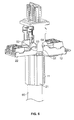
- FIG. 7 shows an assembled connector according to the invention
- FIGS. 8 & 9 illustrate components of the connector of FIG. 7 in more detail
- FIG. 10 shows an alternative embodiment of a connector according to the invention partly assembled
- FIGS. 11 and 12 show the connector of FIG. 10 being further assembled
- FIGS. 13 and 14 show the connector of FIG. 10 fully assembled
- FIG. 15 shows the preferred toothed spring flanges of the cable-enclosing half-shell sub-assemblies.
- FIG. 16 shows the preferred snap-fit slot and rib formations for securing the hinged covers in the closed position on the contact carrier.
- a first sub-assembly 10 of a connector which includes a shell in the form of casing 11 and an electrically-conductive cover 12 , both of which are formed from a metallic alloy known in this field of technology as “Zamak”.
- Cover 12 is pivotally connected to casing 11 and may pivot about axis A.
- Wire-receiving spaces 14 are provided in a plastic lacing fixture 16 which is affixed to the inside of cover 12 .
- a second sub-assembly 20 is shown which is complementary to the first sub-assembly and is similar in construction.
- Cover 22 and casing 21 are formed from Zamak and are pivotally connected about axis B.
- Wire-receiving spaces 24 are provided in lacing fixture 26 .
- Casing 21 is identical to casing 11 .
- the casings 11 and 21 both include removable inserts 13 which include resilient flanges 15 .
- the casings 11 and 21 are arranged to be snap-fitted together about a cable to be terminated to form a cable clamp around the cable.
- a foil-shielded cable is typically used.
- a length of outer insulation is removed from the end of the cable to be terminated and a section of the exposed foil shield is folded back over the cable outer insulation.
- the resilient flanges 15 become compressed about the cable when casings 11 , 21 are snap-fitted together to grip the cable and provide strain relief.
- Inserts 13 are made of electrically conductive material and press against the folded back section of foil to achieve electrical continuity between the foil shield in the cable and the connector.
- Casing 11 includes a lug 17 and a recess 18 .
- Casing 21 includes complementary recess 28 and lug 27 . To snap-fit the casings together lug 17 is snap-fitted into recess 28 and lug 27 is snap-fitted into recess 18 .
- FIGS. 3A to 3G the operation of snap-fitting together the two casings is illustrated.
- the cable is not shown for simplicity.
- casings 11 , 21 are brought together until they touch (see FIG. 3B ).
- Casings are then manipulated so that lugs 17 , 27 align with recesses 18 , 28 (see FIG. 3C ).
- casings are aligned so that recesses 81 , 71 line up with lugs 80 , 70 which are visible in FIGS. 1 and 2 .
- Casings 11 , 21 are then pressed together to arrive at the arrangement shown in FIGS. 3E and 3F .
- Casings 11 , 21 are snap-fitted together by way of the lug and groove formation shown in FIG. 3G .
- a third sub-assembly 40 which includes a carrier 41 formed from Zamak. Eight insulation-displacing contacts 42 are mounted in the carrier and are insulated from the carrier by plastic inserts. The insulation-displacing contacts are in electrical connection with plug contacts 43 which are housed in insulating contact holder 49 , which may be integral with the aforementioned plastic inserts.
- Carrier 41 is to be assembled with the first and second sub-assemblies to form a connector. Note that lug 45 will locate in groove 46 .
- Carrier 41 also includes recesses 44 which are used to retain the carrier in the assembled connector as will now be described.
- the connector is shown partially assembled.
- Carrier 41 is shown passing by flat portions 51 , 52 of covers 22 , 12 .
- the distance between flat portions 51 and 52 and the relevant lug width are different on the opposite sides of carrier 41 , so that sub-assembly 40 will be assemblable only in its correct position.
- covers 12 and 22 are free to pivot about their respective axes to bring the wires towards the insulation-displacing contacts.
- cam portions 54 , 53 of the covers come into engagement with recesses 44 of carrier 41 .
- the covers 22 , 12 are moved towards their closed position by hand and are pushed to their closed position by gripping about the entire assembly with pliers and squeezing so that the wires are properly engaged with the insulation-displacing contacts.
- the connector is shown fully assembled.
- the covers, casings and carrier serve to completely surround the inside of the connector, thus shielding the wires inside the connector from electromagnetic interference.
- lacing fixture 16 and contact holder 49 are shown.
- the lip 84 of lacing fixture 16 snaps into the recess 85 on the contact holder, thus helping to keep the covers in the closed position.
- FIGS. 10 to 14 show a female or jack type connector, which is similar in construction to the male or plug type connector shown in FIGS. 5 to 7 , and is intended to mate with the plug type connector.
- the main difference of the jack connector from the plug connector is found in the contact carrier 140 .
- contact carrier 140 provides a female type connection in the form of a recess generally indicated by arrow 160 which accommodates the male type connector previously described.
- Recess 160 may be protected by dust cover 150 .
- FIG. 15 illustrates the aforementioned preferred toothed spring flanges 15 in the upper and lower cable-gripping sub-assemblies 11 , 21 .
- FIG. 16 illustrates the addition of ribs 410 in the carrier 41 and slots 120 , 220 in the hinged covers 12 , 22 , which ribs snap-fit into the slots to hold the covers 12 , 22 releasably in the closed position around the contact carrier 41 .
- the end of the finished connector which bears the plug contacts extends away from the cable substantially in line with the axis of the cable.
- alternative constructions where the plug contacts extend at an angle to the axis of the cable may be employed.
- the electrically shielding parts are formed from Zamak, but other metals or electrically conductive materials could be used.
- a mould-over process may be used to form these components from a metal sheet surrounded by a moulded plastics material.
- Parts made of plastics in the embodiments described above could alternatively be made of other dielectric materials.
- connectors with eight sets of contacts are described, but other numbers of contacts could be used, even odd numbers, and the insulation-displacing contacts described could be replaced by other types of contacts as previously mentioned.
- the cable may include a foil shield or a braided shield, or both foil and braided shields could be present.
- the cable-surrounding casings were of identical (“mirror image”) construction.
- casings of dissimilar construction could be used, provided that they are dimensioned to mate together in an appropriate manner.
- the casings may be provided as separate components, or could be provided as a hinged component including two half shells joined along one side of their length.
- the present invention includes connectors having the convenient pivoting structure of the present invention wherein some or all of the shielding parts described above may be replaced by plastics parts or other electrically insulating parts when less-shielded or unshielded connectors are required.
Landscapes
- Details Of Connecting Devices For Male And Female Coupling (AREA)
- Multi-Conductor Connections (AREA)
- Coupling Device And Connection With Printed Circuit (AREA)
Abstract
Description
Claims (28)
Applications Claiming Priority (3)
| Application Number | Priority Date | Filing Date | Title |
|---|---|---|---|
| GB0625061.7 | 2006-12-15 | ||
| GBGB0625061.7A GB0625061D0 (en) | 2006-12-15 | 2006-12-15 | A connector for use in terminating communications cables |
| PCT/GB2007/004658 WO2008071917A1 (en) | 2006-12-15 | 2007-12-05 | A connector for use in terminating communications cables |
Publications (2)
| Publication Number | Publication Date |
|---|---|
| US20100015844A1 US20100015844A1 (en) | 2010-01-21 |
| US8070506B2 true US8070506B2 (en) | 2011-12-06 |
Family
ID=37712221
Family Applications (1)
| Application Number | Title | Priority Date | Filing Date |
|---|---|---|---|
| US12/518,931 Expired - Fee Related US8070506B2 (en) | 2006-12-15 | 2007-12-05 | Connector for use in terminating communications cables |
Country Status (11)
| Country | Link |
|---|---|
| US (1) | US8070506B2 (en) |
| EP (1) | EP2092609B8 (en) |
| CN (1) | CN101595601B (en) |
| AU (1) | AU2007331306B2 (en) |
| BR (1) | BRPI0720096B1 (en) |
| CA (1) | CA2672232C (en) |
| CO (1) | CO6210713A2 (en) |
| ES (1) | ES2637016T3 (en) |
| GB (1) | GB0625061D0 (en) |
| MX (1) | MX2009006332A (en) |
| WO (1) | WO2008071917A1 (en) |
Cited By (15)
| Publication number | Priority date | Publication date | Assignee | Title |
|---|---|---|---|---|
| US20120094525A1 (en) * | 2010-10-18 | 2012-04-19 | Panduit Corp. | Communication Plug with Improved Cable Manager |
| US9033725B2 (en) * | 2012-04-19 | 2015-05-19 | Panduit Corp. | GG45 plug with hinging load bar |
| US20160072235A1 (en) * | 2013-05-21 | 2016-03-10 | Te Connectivity Germany Gmbh | Electrical Connector |
| US20160164223A1 (en) * | 2013-07-11 | 2016-06-09 | Rosenberger Hochfrequenztechnik Gmbh & Co. Kg | Plug connector |
| US20170005444A1 (en) * | 2014-04-11 | 2017-01-05 | HARTING Electronics GmbH | Plug-in connector |
| US20180090899A1 (en) * | 2015-03-20 | 2018-03-29 | CommScope Connectivity Spain, S.L. | Connector with separable lacing fixture |
| US20180277977A1 (en) * | 2017-03-24 | 2018-09-27 | Alpine Electronics, Inc. | Structure of electrical connector casing and method of using same |
| US10148048B2 (en) | 2016-05-20 | 2018-12-04 | Communications Systems, Inc. | Toolless communications jack |
| US11228132B2 (en) * | 2019-07-01 | 2022-01-18 | Panduit Corp. | Single pair ethernet field terminable connector |
| US11342718B2 (en) | 2015-03-27 | 2022-05-24 | CommScope Connectivity Spain, S.L. | Latch for telecommunications connector |
| US11356752B2 (en) | 2017-11-10 | 2022-06-07 | Commscope Technologies Llc | Telecommunications panel with grounding wire |
| US11356751B2 (en) | 2017-06-19 | 2022-06-07 | Commscope Technologies Llc | High density bezel for patch panel |
| US11367985B2 (en) | 2016-08-15 | 2022-06-21 | Commscope Technologies Llc | Connector assembly with grounding |
| US20230057001A1 (en) * | 2021-08-19 | 2023-02-23 | Panduit Corp. | Field terminable ethernet connector with integral termination cap |
| US12206205B2 (en) | 2015-03-27 | 2025-01-21 | CommScope Connectivity Spain, S.L. | Cover assembly for a telecommunications connector |
Families Citing this family (18)
| Publication number | Priority date | Publication date | Assignee | Title |
|---|---|---|---|---|
| US7857635B2 (en) | 2007-09-12 | 2010-12-28 | Commscope, Inc. Of North Carolina | Board edge termination back-end connection assemblies and communications connectors including such assemblies |
| PL2045880T3 (en) * | 2007-10-04 | 2011-06-30 | Corning Res & Dev Corp | A connector in the field of telecommunications |
| GB0914025D0 (en) | 2009-08-11 | 2009-09-16 | 3M Innovative Properties Co | Telecommunications connector |
| US7845968B1 (en) * | 2010-01-12 | 2010-12-07 | Phoenix Contact Development & Manufacturing, Inc. | Electrical connector assembly and method |
| DE102010014295A1 (en) * | 2010-04-08 | 2011-10-13 | Phoenix Contact Gmbh & Co. Kg | Connector for receiving a multi-core cable |
| US8337238B2 (en) | 2010-07-19 | 2012-12-25 | Tyco Electronics Corporation | Cable clip for a connector assembly |
| US8550839B2 (en) | 2011-04-21 | 2013-10-08 | Tyco Electronics Corporation | Cable clamp for cable connector |
| US8574000B1 (en) * | 2012-04-25 | 2013-11-05 | Quality Computer Accessories Inc. | Network cable assembly and protective sleeve thereof |
| DE102014100544A1 (en) * | 2014-01-20 | 2015-07-23 | Reichle + De-Massari Ag | connector device |
| ES2547260A1 (en) | 2014-04-01 | 2015-10-02 | Te Connectivity Amp España, S.L.U. | Screened telecommunications connector |
| CN204067664U (en) * | 2014-08-12 | 2014-12-31 | 泰科电子(上海)有限公司 | electrical connector |
| JP6429078B2 (en) * | 2015-01-29 | 2018-11-28 | 株式会社オートネットワーク技術研究所 | Shield connector |
| DE102016004429B4 (en) * | 2016-04-12 | 2019-03-28 | Dätwyler Cabling Solutions Ag | Socket module for data transmission cable and mounting method for connecting the socket module to the data transmission cable |
| DE102017110546B3 (en) | 2017-05-15 | 2018-07-19 | HARTING Electronics GmbH | Tensile and pressure relief means for a connector housing |
| DE102017110544B3 (en) | 2017-05-15 | 2018-07-19 | HARTING Electronics GmbH | Connector with insulation displacement contact |
| CN113424371B (en) * | 2019-02-15 | 2024-01-30 | 赫斯曼汽车有限公司 | Plug connector with improved protection against high voltage flashovers |
| CN114628924A (en) * | 2020-12-11 | 2022-06-14 | 安费诺商用电子产品(成都)有限公司 | Electrical connector and electronic system |
| FR3145449A1 (en) * | 2023-02-01 | 2024-08-02 | Schneider Electric Industries Sas | Connection device for multi-wire electrical cable and associated complementary devices |
Citations (15)
| Publication number | Priority date | Publication date | Assignee | Title |
|---|---|---|---|---|
| US4037906A (en) * | 1976-03-22 | 1977-07-26 | Gte Sylvania Incorporated | Electrical connector and contact |
| US4094566A (en) | 1977-02-18 | 1978-06-13 | Amp Incorporated | Connector having wire locating means |
| US4181384A (en) * | 1978-02-06 | 1980-01-01 | Amp Incorporated | Flat cable connector having wire deployment means |
| US4367909A (en) * | 1979-04-11 | 1983-01-11 | Amp Incorporated | Ribbon cable connector |
| US4449778A (en) * | 1982-12-22 | 1984-05-22 | Amp Incorporated | Shielded electrical connector |
| US4824383A (en) * | 1986-11-18 | 1989-04-25 | E. I. Du Pont De Nemours And Company | Terminator and corresponding receptacle for multiple electrical conductors |
| US4878853A (en) * | 1988-03-23 | 1989-11-07 | Yazaki Corporation | Locking device for connector assembly |
| US5030133A (en) * | 1990-07-25 | 1991-07-09 | Itt Corporation | Connector with attached caps |
| US5947761A (en) * | 1998-09-29 | 1999-09-07 | The Whitaker Corporation | Electrical connector with pivoting wire fixture |
| US6224423B1 (en) | 1998-01-15 | 2001-05-01 | The Siemon Company | Enhanced performance telecommunications connector |
| US6238235B1 (en) * | 1999-05-10 | 2001-05-29 | Rit Technologies Ltd. | Cable organizer |
| DE10065136A1 (en) | 2000-12-29 | 2002-07-18 | Phoenix Contact Gmbh & Co | Connector device for multi-wire cable has especially RJ45 format plug connector, wire guide element with cable accommodation region, wire guide region next to accommodation region |
| US6682363B1 (en) * | 2003-02-18 | 2004-01-27 | Hsu & Overmatt Co., Ltd. | Insulation piercing connector |
| US7021967B2 (en) * | 2003-11-19 | 2006-04-04 | The Siemon Company | Cable shield contact |
| EP1310019B1 (en) | 2000-08-17 | 2006-11-22 | Tyco Electronics AMP GmbH | Electrical plug for data transmission in an industrial environment |
Family Cites Families (1)
| Publication number | Priority date | Publication date | Assignee | Title |
|---|---|---|---|---|
| US4897041A (en) * | 1989-03-21 | 1990-01-30 | Amp Incorporated | Electrical connector having a cable terminating cover retention system and a strain relief therefor |
-
2006
- 2006-12-15 GB GBGB0625061.7A patent/GB0625061D0/en not_active Ceased
-
2007
- 2007-12-05 CA CA2672232A patent/CA2672232C/en active Active
- 2007-12-05 US US12/518,931 patent/US8070506B2/en not_active Expired - Fee Related
- 2007-12-05 ES ES07824799.6T patent/ES2637016T3/en active Active
- 2007-12-05 CN CN200780046217.4A patent/CN101595601B/en not_active Expired - Fee Related
- 2007-12-05 WO PCT/GB2007/004658 patent/WO2008071917A1/en not_active Ceased
- 2007-12-05 EP EP07824799.6A patent/EP2092609B8/en not_active Not-in-force
- 2007-12-05 BR BRPI0720096-0A patent/BRPI0720096B1/en not_active IP Right Cessation
- 2007-12-05 AU AU2007331306A patent/AU2007331306B2/en not_active Ceased
- 2007-12-05 MX MX2009006332A patent/MX2009006332A/en active IP Right Grant
-
2009
- 2009-06-11 CO CO09061105A patent/CO6210713A2/en not_active Application Discontinuation
Patent Citations (16)
| Publication number | Priority date | Publication date | Assignee | Title |
|---|---|---|---|---|
| US4037906A (en) * | 1976-03-22 | 1977-07-26 | Gte Sylvania Incorporated | Electrical connector and contact |
| US4094566A (en) | 1977-02-18 | 1978-06-13 | Amp Incorporated | Connector having wire locating means |
| US4181384A (en) * | 1978-02-06 | 1980-01-01 | Amp Incorporated | Flat cable connector having wire deployment means |
| US4367909A (en) * | 1979-04-11 | 1983-01-11 | Amp Incorporated | Ribbon cable connector |
| US4449778A (en) * | 1982-12-22 | 1984-05-22 | Amp Incorporated | Shielded electrical connector |
| US4824383A (en) * | 1986-11-18 | 1989-04-25 | E. I. Du Pont De Nemours And Company | Terminator and corresponding receptacle for multiple electrical conductors |
| US4878853A (en) * | 1988-03-23 | 1989-11-07 | Yazaki Corporation | Locking device for connector assembly |
| US5030133A (en) * | 1990-07-25 | 1991-07-09 | Itt Corporation | Connector with attached caps |
| US6328601B1 (en) * | 1998-01-15 | 2001-12-11 | The Siemon Company | Enhanced performance telecommunications connector |
| US6224423B1 (en) | 1998-01-15 | 2001-05-01 | The Siemon Company | Enhanced performance telecommunications connector |
| US5947761A (en) * | 1998-09-29 | 1999-09-07 | The Whitaker Corporation | Electrical connector with pivoting wire fixture |
| US6238235B1 (en) * | 1999-05-10 | 2001-05-29 | Rit Technologies Ltd. | Cable organizer |
| EP1310019B1 (en) | 2000-08-17 | 2006-11-22 | Tyco Electronics AMP GmbH | Electrical plug for data transmission in an industrial environment |
| DE10065136A1 (en) | 2000-12-29 | 2002-07-18 | Phoenix Contact Gmbh & Co | Connector device for multi-wire cable has especially RJ45 format plug connector, wire guide element with cable accommodation region, wire guide region next to accommodation region |
| US6682363B1 (en) * | 2003-02-18 | 2004-01-27 | Hsu & Overmatt Co., Ltd. | Insulation piercing connector |
| US7021967B2 (en) * | 2003-11-19 | 2006-04-04 | The Siemon Company | Cable shield contact |
Non-Patent Citations (1)
| Title |
|---|
| International Search Report for PCT/GB2007/004658 issued by the European Patent Office on May 9, 2008. |
Cited By (31)
| Publication number | Priority date | Publication date | Assignee | Title |
|---|---|---|---|---|
| US10243297B2 (en) | 2010-10-18 | 2019-03-26 | Panduit Corp. | Communications plug with improved cable manager |
| US8702444B2 (en) * | 2010-10-18 | 2014-04-22 | Panduit Corp. | Communication plug with improved cable manager |
| US20140213099A1 (en) * | 2010-10-18 | 2014-07-31 | Panduit Corp. | Communication plug with improved cable manager |
| US8961219B2 (en) * | 2010-10-18 | 2015-02-24 | Panduit Corp. | Communication plug with improved cable manager |
| US20120094525A1 (en) * | 2010-10-18 | 2012-04-19 | Panduit Corp. | Communication Plug with Improved Cable Manager |
| US9799985B2 (en) | 2010-10-18 | 2017-10-24 | Panduit Corp. | Communication plug with improved cable manager |
| US9960529B2 (en) | 2010-10-18 | 2018-05-01 | Panduit Corp. | Communication plug with improved cable manager |
| US9033725B2 (en) * | 2012-04-19 | 2015-05-19 | Panduit Corp. | GG45 plug with hinging load bar |
| US20160072235A1 (en) * | 2013-05-21 | 2016-03-10 | Te Connectivity Germany Gmbh | Electrical Connector |
| US9960549B2 (en) * | 2013-05-21 | 2018-05-01 | Te Connectivity Germany Gmbh | Electrical connector |
| US20160164223A1 (en) * | 2013-07-11 | 2016-06-09 | Rosenberger Hochfrequenztechnik Gmbh & Co. Kg | Plug connector |
| US10389062B2 (en) * | 2013-07-11 | 2019-08-20 | Rosenberger Hochfrequenztechnik Gmbh & Co. Kg | Plug connector |
| US20170005444A1 (en) * | 2014-04-11 | 2017-01-05 | HARTING Electronics GmbH | Plug-in connector |
| US20180090899A1 (en) * | 2015-03-20 | 2018-03-29 | CommScope Connectivity Spain, S.L. | Connector with separable lacing fixture |
| US10784640B2 (en) * | 2015-03-20 | 2020-09-22 | CommScope Connectivity Spain, S.L. | Connector with separable lacing fixture |
| EP3273549B1 (en) * | 2015-03-20 | 2025-02-12 | CommScope Connectivity Spain, S.L. | Connector with separable lacing fixture |
| US11509105B2 (en) | 2015-03-20 | 2022-11-22 | CommScope Connectivity Spain, S.L. | Connector with separable lacing fixture |
| US12355196B2 (en) | 2015-03-27 | 2025-07-08 | CommScope Connectivity Spain, S.L. | Latch for telecommunications connector |
| US11342718B2 (en) | 2015-03-27 | 2022-05-24 | CommScope Connectivity Spain, S.L. | Latch for telecommunications connector |
| US12206205B2 (en) | 2015-03-27 | 2025-01-21 | CommScope Connectivity Spain, S.L. | Cover assembly for a telecommunications connector |
| US10148048B2 (en) | 2016-05-20 | 2018-12-04 | Communications Systems, Inc. | Toolless communications jack |
| US12149032B2 (en) | 2016-08-15 | 2024-11-19 | Commscope Technologies Llc | Connector assembly with grounding |
| US11367985B2 (en) | 2016-08-15 | 2022-06-21 | Commscope Technologies Llc | Connector assembly with grounding |
| US20180277977A1 (en) * | 2017-03-24 | 2018-09-27 | Alpine Electronics, Inc. | Structure of electrical connector casing and method of using same |
| US10530103B2 (en) * | 2017-03-24 | 2020-01-07 | Alpine Electronics, Inc. | Structure of electrical connector casing |
| US11356751B2 (en) | 2017-06-19 | 2022-06-07 | Commscope Technologies Llc | High density bezel for patch panel |
| US11838700B2 (en) | 2017-06-19 | 2023-12-05 | Commscope Technologies Llc | High density bezel for patch panel |
| US11356752B2 (en) | 2017-11-10 | 2022-06-07 | Commscope Technologies Llc | Telecommunications panel with grounding wire |
| US11228132B2 (en) * | 2019-07-01 | 2022-01-18 | Panduit Corp. | Single pair ethernet field terminable connector |
| US11705681B2 (en) * | 2021-08-19 | 2023-07-18 | Panduit Corp. | Field terminable ethernet connector with integral termination cap |
| US20230057001A1 (en) * | 2021-08-19 | 2023-02-23 | Panduit Corp. | Field terminable ethernet connector with integral termination cap |
Also Published As
| Publication number | Publication date |
|---|---|
| CA2672232A1 (en) | 2008-06-19 |
| EP2092609B1 (en) | 2017-05-24 |
| CN101595601B (en) | 2014-10-29 |
| CN101595601A (en) | 2009-12-02 |
| EP2092609B8 (en) | 2017-08-02 |
| CA2672232C (en) | 2016-06-14 |
| EP2092609A1 (en) | 2009-08-26 |
| AU2007331306A1 (en) | 2008-06-19 |
| MX2009006332A (en) | 2009-06-23 |
| WO2008071917A1 (en) | 2008-06-19 |
| ES2637016T3 (en) | 2017-10-10 |
| GB0625061D0 (en) | 2007-01-24 |
| CO6210713A2 (en) | 2010-10-20 |
| BRPI0720096A2 (en) | 2013-12-24 |
| BRPI0720096B1 (en) | 2018-05-29 |
| AU2007331306B2 (en) | 2011-06-16 |
| US20100015844A1 (en) | 2010-01-21 |
Similar Documents
| Publication | Publication Date | Title |
|---|---|---|
| US8070506B2 (en) | Connector for use in terminating communications cables | |
| US5052949A (en) | Shielded electrical connector | |
| US4460230A (en) | Connector hood constructions | |
| US4310213A (en) | Electrical connector kit | |
| EP2369690B1 (en) | Electrical connector | |
| USRE32760E (en) | Electrical connector | |
| JPH0226348B2 (en) | ||
| US8057250B2 (en) | Cable organizer for electrical connector | |
| GB2042827A (en) | Connector hood constructions | |
| US5074803A (en) | Latching mechanism for shielded data connector | |
| US20140302714A1 (en) | Plug-in connector | |
| US20050282438A1 (en) | Shielded connector | |
| JP2000156261A (en) | Shield connector | |
| US9774103B2 (en) | Radial termination system for a communication connector | |
| CN111512500A (en) | Connector with extendable lever assembly | |
| KR20250143109A (en) | Angled connector | |
| US11996657B2 (en) | Connector including male and female connectors | |
| US20260005477A1 (en) | Terminal assembly for ethernet connector | |
| CN201029167Y (en) | Cable Connector Assembly | |
| JP3118903B2 (en) | Data connector | |
| US20250219333A1 (en) | High Voltage Shielded Electrical Connector | |
| US20250219330A1 (en) | High voltage shielded electrical connector | |
| JP2021022536A (en) | connector | |
| KR970004149B1 (en) | Latching mechanism for shielded data connector | |
| IE852653L (en) | Shielded electrical connector |
Legal Events
| Date | Code | Title | Description |
|---|---|---|---|
| AS | Assignment |
Owner name: TYCO ELECTRONICS AMP ESPANA SA,SPAIN Free format text: ASSIGNMENT OF ASSIGNORS INTEREST;ASSIGNORS:DE DIOS MARTIN, LONGINOS;MAQUEDA GONZALEZ, MARIA;CHAMORRO DAVALOS, FRANCISCO CARLOS;SIGNING DATES FROM 20090116 TO 20090203;REEL/FRAME:022817/0534 Owner name: TYCO ELECTRONICS AMP ESPANA SA, SPAIN Free format text: ASSIGNMENT OF ASSIGNORS INTEREST;ASSIGNORS:DE DIOS MARTIN, LONGINOS;MAQUEDA GONZALEZ, MARIA;CHAMORRO DAVALOS, FRANCISCO CARLOS;SIGNING DATES FROM 20090116 TO 20090203;REEL/FRAME:022817/0534 |
|
| ZAAA | Notice of allowance and fees due |
Free format text: ORIGINAL CODE: NOA |
|
| ZAAB | Notice of allowance mailed |
Free format text: ORIGINAL CODE: MN/=. |
|
| STCF | Information on status: patent grant |
Free format text: PATENTED CASE |
|
| FPAY | Fee payment |
Year of fee payment: 4 |
|
| AS | Assignment |
Owner name: TE CONNECTIVITY AMP ESPANA S.L.U., SPAIN Free format text: CHANGE OF NAME;ASSIGNOR:TYCO ELECTRONICS AMP ESPANA S.A.;REEL/FRAME:036314/0055 Effective date: 20121128 |
|
| MAFP | Maintenance fee payment |
Free format text: PAYMENT OF MAINTENANCE FEE, 8TH YEAR, LARGE ENTITY (ORIGINAL EVENT CODE: M1552); ENTITY STATUS OF PATENT OWNER: LARGE ENTITY Year of fee payment: 8 |
|
| AS | Assignment |
Owner name: TE CONNECTIVITY BROADBAND SOLUTIONS SPAIN, S.L.U., SPAIN Free format text: ASSIGNMENT OF ASSIGNORS INTEREST;ASSIGNOR:TE CONNECTIVITY AMP ESPANA, S.L.U.;REEL/FRAME:060201/0815 Effective date: 20150930 |
|
| AS | Assignment |
Owner name: COMMSCOPE CONNECTIVITY SPAIN, S.L., SPAIN Free format text: CHANGE OF NAME;ASSIGNOR:TE CONNECTIVITY BROADBAND SOLUTIONS SPAIN, S.L.U.;REEL/FRAME:060203/0441 Effective date: 20151204 |
|
| FEPP | Fee payment procedure |
Free format text: MAINTENANCE FEE REMINDER MAILED (ORIGINAL EVENT CODE: REM.); ENTITY STATUS OF PATENT OWNER: LARGE ENTITY |
|
| LAPS | Lapse for failure to pay maintenance fees |
Free format text: PATENT EXPIRED FOR FAILURE TO PAY MAINTENANCE FEES (ORIGINAL EVENT CODE: EXP.); ENTITY STATUS OF PATENT OWNER: LARGE ENTITY |
|
| STCH | Information on status: patent discontinuation |
Free format text: PATENT EXPIRED DUE TO NONPAYMENT OF MAINTENANCE FEES UNDER 37 CFR 1.362 |
|
| FP | Lapsed due to failure to pay maintenance fee |
Effective date: 20231206 |