US8065834B2 - Two piece plant container with water reservoir - Google Patents
Two piece plant container with water reservoir Download PDFInfo
- Publication number
- US8065834B2 US8065834B2 US12/660,525 US66052510A US8065834B2 US 8065834 B2 US8065834 B2 US 8065834B2 US 66052510 A US66052510 A US 66052510A US 8065834 B2 US8065834 B2 US 8065834B2
- Authority
- US
- United States
- Prior art keywords
- water
- inner part
- plant container
- container according
- bottom wall
- Prior art date
- Legal status (The legal status is an assumption and is not a legal conclusion. Google has not performed a legal analysis and makes no representation as to the accuracy of the status listed.)
- Active, expires
Links
Images


Classifications
-
- A—HUMAN NECESSITIES
- A01—AGRICULTURE; FORESTRY; ANIMAL HUSBANDRY; HUNTING; TRAPPING; FISHING
- A01G—HORTICULTURE; CULTIVATION OF VEGETABLES, FLOWERS, RICE, FRUIT, VINES, HOPS OR SEAWEED; FORESTRY; WATERING
- A01G9/00—Cultivation in receptacles, forcing-frames or greenhouses; Edging for beds, lawn or the like
- A01G9/02—Receptacles, e.g. flower-pots or boxes; Glasses for cultivating flowers
- A01G9/028—Multi-compartmented pots
-
- A—HUMAN NECESSITIES
- A01—AGRICULTURE; FORESTRY; ANIMAL HUSBANDRY; HUNTING; TRAPPING; FISHING
- A01G—HORTICULTURE; CULTIVATION OF VEGETABLES, FLOWERS, RICE, FRUIT, VINES, HOPS OR SEAWEED; FORESTRY; WATERING
- A01G27/00—Self-acting watering devices, e.g. for flower-pots
- A01G27/02—Self-acting watering devices, e.g. for flower-pots having a water reservoir, the main part thereof being located wholly around or directly beside the growth substrate
Definitions
- This invention concerns plant containers and more particularly plant containers which have a built-in water reservoir to reduce the need for frequent watering.
- Municipalities commonly maintain large numbers container plantings hanging from light poles, etc., for decorative effect, and a need for frequent watering presents a substantial burden on city resources.
- a two part container of molded plastic an outer tub part having a bottom region defining a reservoir space and which receives an inner holder part nested within an upper region of the outer part and which holds the soil and planting.
- the side wall of the outer tub part has a plurality of inwardly projecting steps formed about the perimeter defining horizontal support surfaces arranged about its interior on which a bottom wall of the inner part rests, located just above the water reservoir.
- At least one of the support surfaces has a localized depressed space communicating with the reservoir space such that water can flow beneath an inner part bottom wall even while resting on the step surfaces to a drain hole in the bottom of the depressed space.
- the drain hole establishes a maximum level of water in the reservoir space.
- the bottom of the inner container has a pattern of openings in a major area of its bottom wall which is located just above the maximum water level in the reservoir to allow the planting roots to quickly grow into the water in the reservoir through the openings to allow water to be absorbed by the plant in addition to moisture in the soil being absorbed without danger of waterlogging the soil by a wicking action.
- the planting can be thoroughly watered by pouring water into the soil mass with any excess draining into the reservoir space until the water overflows but through the drain hole with such outflow indicating to the person watering the plant that the reservoir space is filled to the maximum so that watering can be stopped.
- a series of radial ribs converging into a center connection are molded therein to stiffen the bottom wall.
- These ribs may continue up the side wall for large containers such that the inner container is sturdy enough to support the soil and plant independently of the outer tub part.
- the perimeter wall of the inner part of the container is radially indented at locations on either side thereof and open at the top to create hand grip features enabling the fingers of each hand and to be inserted therein and to be wrapped around undersurfaces, providing convenient handholds allowing easy gripping and lifting out of the inner container part from the outer part.
- the steps formed into the perimeter of the outer tub part also provide handholds for lifting both parts.
- a removable plug in a drain hole in the bottom of the reservoir allows substantially complete draining when both parts of the container is to be removed.
- FIG. 1 is a pictorial view of a two part plant container according to the invention.
- FIG. 2 is a pictorial exploded view of an outer tub part and an inner plant holder part of the container shown in FIG. 1 .
- FIG. 3 is an exploded side elevational view of the two parts shown in FIG. 2 .
- FIG. 4 is a side-by-side top view of the two parts shown in FIGS. 2 and 3 .
- FIG. 5 is a side-by-side bottom view of the two parts shown in FIGS. 2 and 4 .
- FIG. 6 is a transverse sectional view through the two part container shown in FIG. 1 .
- FIG. 7 is an exploded pictorial view of an alternate form of the two part container according to the invention.
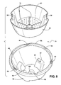
- FIG. 8 is an exploded pictorial view of a smaller two part container according to the invention.
- a two part container 10 includes outer tub part 12 and a shorter height, bowl shaped plant holder inner part 14 nested within an upper region 16 of the outer part 12 .
- Both container parts 12 , 14 are molded from a durable plastic material.
- the outer part has four indented step features 18 formed into the perimeter of a lower region 20 , creating a series of radially inward extending aligned horizontal flat support surfaces 22 arrayed about the inner perimeter of the outer part 12 .
- the inner container part 14 has a generally flat bottom with an annular flat undersurface area 24 which is located to rest on the top of the surface 22 of the step features 18 .
- the lower region 20 within the outer part 12 defines a reservoir space 26 for storing water.
- One (or more) of the step flat surfaces 22 is formed with a depressed area 30 extending radially into the reservoir space 26 to be in fluid communication therewith, with a hole 32 penetrating through the thickness defining the surface 22 to allow outflow of water when reaching that level of the surface of the depressed area 30 .
- the inner holder part 14 bottom is formed with wedge shaped lower flat areas 34 intermediate a series of raised radial ribs 36 converging together around a central lower area 38 .
- Each of the lower flat areas 34 have a plurality of through openings extending therein which may be an array of holes 40 as shown or a pattern of slots described hereinafter.
- the level of the lower flat areas 34 is set to be just above or even with the upper surface 30 A of depressed area 30 . This insures that the level of water in the reservoir space 26 does not reach the bottom of the soil space 42 in the inner container 14 but is very close, i.e., a distance approximately equal to the bottom wall thickness of the inner container, i.e., approximately 1 ⁇ 8 inch.
- This small gap allows the roots to quickly grow into the water in the reservoir while insuring that the soil mass remains isolated from the water in the reservoir space 26 at its highest level.
- the bottom wall of the inner container 14 is stiffened by the series of radially convergent ribs 36 which join each other as seen in FIG. 4 , the ends arranged around a generally hexagonal center area 42 .
- Four of the ribs 36 have portions 44 which continue up the sidewall 46 to stiffen the sidewall 44 as well.
- the sidewall 46 is formed with generally rectangular radially inward indentations 48 creating an opening 50 between the inside of the outer container part 12 and the outer side of the indentations 48 .
- the openings 50 are sized to comfortably allow insertion of the four fingers of a person's hand, i.e., approximately a 5 inch wide opening.
- the top of the indentation 40 includes a shoulder 52 which forms an undersurface which extends radially inwardly and allows a person to hook the tips of his or her fingers behind the indentation after insertion of his fingers into opening 50 so that the inner container part 14 can conveniently be lifted out of the outer part 12 .
- the shoulders 18 also provide convenient exterior handholds for lifting the outer part 12 .
- the ribs 36 blend into the indentations 40 as shown to further strengthen the side wall 46 .
- a drain hole 54 is formed in the bottom of a central raised area 56 in the center of the outer part bottom wall 58 which is normally closed with a plug 60 but can be removed to conveniently enable draining water from the reservoir space 26 as when the entire container 10 is to be moved.
- a series of perimeter holes 62 can be provided in the rim 64 of the outer tub part 12 for attachment of hanging elements, such as wires, etc.
- FIG. 7 shows a two part container 66 according to the invention in which a series of slots 68 are formed in the bottom wall 70 of the inner part 72 of the container 66 instead of the holes 40 in the above described embodiment.
- FIG. 8 shows another embodiment of a smaller container 74 also comprised of an outer tube part 76 and an inner holder part.
- the ribs here comprise radially convergent ridges 78 molded into the bottom wall 82 of the inner part 80 .
- the outer part 76 has alternate loop features 84 and holes 86 in the rim 88 for attachment of support wires, etc. (not shown).
- Step features 90 in the outer part 76 are provided for supporting the inner part 80 with a drain hole 92 in a depressed area 94 setting the maximum water level in a reservoir space 96 opposite hand grip features 98 are molded into the upper wall of the inner part 80 .
- a normally plugged drain hole 100 is formed in the bottom of the outer part 76 .
- water is poured into the inner container 14 to saturate the soil mass, with excess water then passing into and collected in the reservoir space 26 until reaching the level of the hole 32 where outflow may be observed to provide an indication that the reservoir space 26 is full.
- the inner part can be conveniently lifted out for changing plantings if desired; and the outer tub part 12 can be conveniently handled via the hand grip indentations 18 .
- both of the two parts is easily molded, offers sturdy support for the weight of the soil, planting and water, as well as to accurately locate the parts properly.
Landscapes
- Life Sciences & Earth Sciences (AREA)
- Environmental Sciences (AREA)
- Engineering & Computer Science (AREA)
- Water Supply & Treatment (AREA)
- Cultivation Receptacles Or Flower-Pots, Or Pots For Seedlings (AREA)
Abstract
A two part plant container includes an outer tub part having a series of step indentations around its perimeter forming horizontal rest surfaces within the outer part which are located above a lower region forming a water reservoir space. The inner part has a bottom wall areas resting on the surfaces with the inner part nested within an upper region of the outer part. A drain hole is formed through a depressed area in one of the rest surface to set the maximum water level in the reservoir which is just below lower areas of the inner part bottom wall set at the same level as the drain hole. This insures that the soil in the inner part is never wet by the water in the reservoir to prevent wicking and waterlogging of the soil while leaving only a very short gap for the roots of a plant to grow across to reach the water. Handhold features are formed into the perimeter wall of the inner part allowing easy lift out. Ribs are formed into the inner part bottom wall to stiffen the same.
Description
This application claims the benefit of U.S. provisional application No. 61/208,846 filed on Feb. 27, 2009.
This invention concerns plant containers and more particularly plant containers which have a built-in water reservoir to reduce the need for frequent watering. Municipalities commonly maintain large numbers container plantings hanging from light poles, etc., for decorative effect, and a need for frequent watering presents a substantial burden on city resources.
There have heretofore been developed containers with a built-in water reservoir which is situated to allow the planting to draw water from the reservoir in addition to the moisture in the soil in which the plant is growing.
In such large scale deployment of containers, it is common to frequently switch plantings for achieving seasonal displays or to rotate out plantings which are not doing well in favor of more healthy specimens. Such practice also entails considerable labor particularly when large plants and containers are involved.
In the practice of including a water reservoir defined within the container, it is important to prevent excessive water from being wicked into the soil mass as this will cause waterlogging of the soil which will cause the roots to die from disease and lack of air. If the reservoir were overfilled, this will result may occur.
It is an object of the present invention to provide a plant container which includes a water reservoir which is isolated from the soil to prevent saturation of the soil, but is spaced only a very short distance therefrom so as to allow growth of roots into the reservoir space.
It is another object to provide a two part container which allows easy removal of the inner container holding the soil and planting, as well as convenient lifting and handling of the outer container part.
It is yet another object to provide a two part container which is sturdy enough to hold heavy plantings and which has contours which are easily molded from plastic.
The above recited objects and other objects which will be understood by those with knowledge of this art are achieved by a two part container of molded plastic, an outer tub part having a bottom region defining a reservoir space and which receives an inner holder part nested within an upper region of the outer part and which holds the soil and planting.
The side wall of the outer tub part has a plurality of inwardly projecting steps formed about the perimeter defining horizontal support surfaces arranged about its interior on which a bottom wall of the inner part rests, located just above the water reservoir.
At least one of the support surfaces has a localized depressed space communicating with the reservoir space such that water can flow beneath an inner part bottom wall even while resting on the step surfaces to a drain hole in the bottom of the depressed space.
The drain hole establishes a maximum level of water in the reservoir space.
The bottom of the inner container has a pattern of openings in a major area of its bottom wall which is located just above the maximum water level in the reservoir to allow the planting roots to quickly grow into the water in the reservoir through the openings to allow water to be absorbed by the plant in addition to moisture in the soil being absorbed without danger of waterlogging the soil by a wicking action.
The planting can be thoroughly watered by pouring water into the soil mass with any excess draining into the reservoir space until the water overflows but through the drain hole with such outflow indicating to the person watering the plant that the reservoir space is filled to the maximum so that watering can be stopped.
Further drainage from the soil will also flow out through the drainage hole.
In order to provide a sturdy bottom wall easily capable of supporting the weight of the soil and plantings in the inner part, a series of radial ribs converging into a center connection are molded therein to stiffen the bottom wall.
These ribs may continue up the side wall for large containers such that the inner container is sturdy enough to support the soil and plant independently of the outer tub part.
The perimeter wall of the inner part of the container is radially indented at locations on either side thereof and open at the top to create hand grip features enabling the fingers of each hand and to be inserted therein and to be wrapped around undersurfaces, providing convenient handholds allowing easy gripping and lifting out of the inner container part from the outer part.
The steps formed into the perimeter of the outer tub part also provide handholds for lifting both parts.
A removable plug in a drain hole in the bottom of the reservoir allows substantially complete draining when both parts of the container is to be removed.
In the following detailed description, certain specific terminology will be employed for the sake of clarity and a particular embodiment described in accordance with the requirements of 35 USC 112, but it is to be understood that the same is not intended to be limiting and should not be so construed inasmuch as the invention is capable of taking many forms and variations within the scope of the appended claims.
Referring to the drawings, a two part container 10 according to the invention includes outer tub part 12 and a shorter height, bowl shaped plant holder inner part 14 nested within an upper region 16 of the outer part 12.
Both container parts 12, 14 are molded from a durable plastic material. The outer part has four indented step features 18 formed into the perimeter of a lower region 20, creating a series of radially inward extending aligned horizontal flat support surfaces 22 arrayed about the inner perimeter of the outer part 12.
The inner container part 14 has a generally flat bottom with an annular flat undersurface area 24 which is located to rest on the top of the surface 22 of the step features 18.
This stably supports the weight of the inner part and the soil and planting contained therein within the outer part 12.
The lower region 20 within the outer part 12 defines a reservoir space 26 for storing water.
One (or more) of the step flat surfaces 22 is formed with a depressed area 30 extending radially into the reservoir space 26 to be in fluid communication therewith, with a hole 32 penetrating through the thickness defining the surface 22 to allow outflow of water when reaching that level of the surface of the depressed area 30.
The inner holder part 14 bottom is formed with wedge shaped lower flat areas 34 intermediate a series of raised radial ribs 36 converging together around a central lower area 38.
Each of the lower flat areas 34 have a plurality of through openings extending therein which may be an array of holes 40 as shown or a pattern of slots described hereinafter.
The level of the lower flat areas 34 is set to be just above or even with the upper surface 30A of depressed area 30. This insures that the level of water in the reservoir space 26 does not reach the bottom of the soil space 42 in the inner container 14 but is very close, i.e., a distance approximately equal to the bottom wall thickness of the inner container, i.e., approximately ⅛ inch.
This small gap allows the roots to quickly grow into the water in the reservoir while insuring that the soil mass remains isolated from the water in the reservoir space 26 at its highest level.
The bottom wall of the inner container 14 is stiffened by the series of radially convergent ribs 36 which join each other as seen in FIG. 4 , the ends arranged around a generally hexagonal center area 42. Four of the ribs 36 have portions 44 which continue up the sidewall 46 to stiffen the sidewall 44 as well.
At two opposite locations the sidewall 46 is formed with generally rectangular radially inward indentations 48 creating an opening 50 between the inside of the outer container part 12 and the outer side of the indentations 48.
The openings 50 are sized to comfortably allow insertion of the four fingers of a person's hand, i.e., approximately a 5 inch wide opening. The top of the indentation 40 includes a shoulder 52 which forms an undersurface which extends radially inwardly and allows a person to hook the tips of his or her fingers behind the indentation after insertion of his fingers into opening 50 so that the inner container part 14 can conveniently be lifted out of the outer part 12.
The shoulders 18 also provide convenient exterior handholds for lifting the outer part 12.
The ribs 36 blend into the indentations 40 as shown to further strengthen the side wall 46.
A drain hole 54 is formed in the bottom of a central raised area 56 in the center of the outer part bottom wall 58 which is normally closed with a plug 60 but can be removed to conveniently enable draining water from the reservoir space 26 as when the entire container 10 is to be moved.
A series of perimeter holes 62 can be provided in the rim 64 of the outer tub part 12 for attachment of hanging elements, such as wires, etc.
The outer part 76 has alternate loop features 84 and holes 86 in the rim 88 for attachment of support wires, etc. (not shown). Step features 90 in the outer part 76 are provided for supporting the inner part 80 with a drain hole 92 in a depressed area 94 setting the maximum water level in a reservoir space 96 opposite hand grip features 98 are molded into the upper wall of the inner part 80.
A normally plugged drain hole 100 is formed in the bottom of the outer part 76.
In use, water is poured into the inner container 14 to saturate the soil mass, with excess water then passing into and collected in the reservoir space 26 until reaching the level of the hole 32 where outflow may be observed to provide an indication that the reservoir space 26 is full.
At this level there is only a short gap (⅛ inch) between the soil mass and the level of water in the reservoir to insure no wicking of water up into the soil mass, but allow roots to quickly grow into the water.
The inner part can be conveniently lifted out for changing plantings if desired; and the outer tub part 12 can be conveniently handled via the hand grip indentations 18.
The shape of both of the two parts is easily molded, offers sturdy support for the weight of the soil, planting and water, as well as to accurately locate the parts properly.
Claims (10)
1. A two part plant container comprising:
an outer tub-shaped part;
an inner bowl shaped holder part nested into an upper region of said outer tub part with a water reservoir space in said outer part defined spaced below a bottom wall of said inner part;
said inner part resting on a plurality of radially inwardly extending surfaces formed into a sidewall of said outer part so as to define a series of aligned horizontal surfaces on which said inner part is supported nested within said upper region of said outer part; said inner part bottom wall having regions formed with an array of openings therethrough allowing drainage of water into said reservoir space.
2. The two part plant container according to claim 1 wherein said inner container has a sidewall nested into said upper region of said upper part, with a pair of oppositely located inwardly formed handhold opening features defined between said inner perimeter of said outer part and an outer perimeter of said side wall configured to allow insertion of the fingers of a person's hand therein to allow lifting out of said inner part.
3. The two part plant container according to claim 2 wherein each of said handhold features additionally include an undersurface extending further in radially from said handhold opening feature to create a contour for hooking the fingers to provide an additional laid in lifting out said inner part of said container from said outer part.
4. The two part plant container according to claim 1 wherein at least one of said horizontal surfaces includes a depressed area extending inwardly to said reservoir space, with a through drain opening therein allowing outflow of water beneath an inner part undersurface resting thereon to set the maximum water level in said reservoir space.
5. The two part plant container according to claim 4 wherein said inner part bottom all includes a lowermost area region lying inward from and slightly below said undersurfaces to be substantially level with said depressed area whereby the maximum level of water in said reservoir space is beneath an upper surface of said lowermost region of said bottom wall of said inner part to prevent contact of soil therein with water in said reservoir space.
6. The two part plant container according to claim 5 wherein said regions formed with through openings are within said lowermost regions of said bottom wall.
7. The two part plant container according to claim 1 further including a series of ribs radially extending inwardly from said side wall and converging together at a center region thereof to reinforce said bottom wall.
8. The two part plant container according to claim 7 wherein wedge shaped lower regions are intermediate said ribs with said through openings are formed in said wedge shaped regions.
9. The two part plant container according to claim 7 wherein at least some of said ribs extend up said side wall of said inner part.
10. The two part plant container according to claim 1 wherein said outer part has an outturned rim around an upper perimeter edge and a series of hanger holes is formed about said rim.
Priority Applications (1)
| Application Number | Priority Date | Filing Date | Title |
|---|---|---|---|
| US12/660,525 US8065834B2 (en) | 2009-02-27 | 2010-02-26 | Two piece plant container with water reservoir |
Applications Claiming Priority (2)
| Application Number | Priority Date | Filing Date | Title |
|---|---|---|---|
| US20884609P | 2009-02-27 | 2009-02-27 | |
| US12/660,525 US8065834B2 (en) | 2009-02-27 | 2010-02-26 | Two piece plant container with water reservoir |
Publications (2)
| Publication Number | Publication Date |
|---|---|
| US20100218422A1 US20100218422A1 (en) | 2010-09-02 |
| US8065834B2 true US8065834B2 (en) | 2011-11-29 |
Family
ID=42666378
Family Applications (1)
| Application Number | Title | Priority Date | Filing Date |
|---|---|---|---|
| US12/660,525 Active 2030-08-07 US8065834B2 (en) | 2009-02-27 | 2010-02-26 | Two piece plant container with water reservoir |
Country Status (1)
| Country | Link |
|---|---|
| US (1) | US8065834B2 (en) |
Cited By (21)
| Publication number | Priority date | Publication date | Assignee | Title |
|---|---|---|---|---|
| USD671807S1 (en) * | 2011-09-23 | 2012-12-04 | Woodchuck Landscape Systems | Root director |
| USD675492S1 (en) * | 2012-02-01 | 2013-02-05 | Art James D | Self-watering insert for bucket |
| USD683201S1 (en) * | 2011-06-15 | 2013-05-28 | Woodchuck Landscape Systems | Root director |
| US8608401B2 (en) | 2009-08-14 | 2013-12-17 | Ben Gooden | Modulated structural cell for supporting a tree root network |
| US20150027046A1 (en) * | 2013-07-26 | 2015-01-29 | Steven Adolf | Planter system |
| WO2015192442A1 (en) * | 2014-06-16 | 2015-12-23 | 何超群 | New plant planting auxiliary apparatus |
| WO2016018689A1 (en) * | 2014-08-01 | 2016-02-04 | Karl Eckert | Pole and wall adaptable plant container assembly and bracket |
| USD776562S1 (en) | 2015-07-22 | 2017-01-17 | Eckert's Greenhouse Inc. | Planter assembly |
| US9668428B1 (en) * | 2013-04-19 | 2017-06-06 | Pam Frame | Sectional detachable flower pots |
| USD796379S1 (en) * | 2015-08-27 | 2017-09-05 | Takasho Co., Ltd. | Planter |
| US20180070544A1 (en) * | 2016-09-12 | 2018-03-15 | Herman Lorenzo Campbell | Direct Water Feed Plant Container |
| US9930840B1 (en) * | 2016-10-05 | 2018-04-03 | Franc Gergek | Potted plant system |
| US20180213728A1 (en) * | 2017-01-31 | 2018-08-02 | Harold Lorain Kelly | Planter base attachment for open-ended products |
| US10398098B2 (en) | 2016-10-05 | 2019-09-03 | Franc Gergek | Potted plant system |
| US10415260B2 (en) | 2017-11-13 | 2019-09-17 | Strata Innovations Pty Limited | Structural cells, matrices and methods of assembly |
| US10492377B2 (en) | 2016-06-01 | 2019-12-03 | Dee Volin | Unique rollable five-device-in-one system comprising rollable clawed-foot flower container, rollable adjustable-receiver umbrella stand, rollable water reservoir, rollable water-regulating irrigation system, and rollable water-circulating system |
| US11382287B2 (en) * | 2020-09-29 | 2022-07-12 | Vaughn Allen | Automated plant pot assembly |
| US11490574B2 (en) * | 2017-11-03 | 2022-11-08 | Republic Of Korea(Management : Rural Development Administration) | Flower water receiver |
| US11553653B2 (en) * | 2016-07-08 | 2023-01-17 | Rodney James Middleton | Plant pot |
| US11882800B2 (en) | 2022-06-29 | 2024-01-30 | Franc Gergek | Programmable bucket and method of use and manufacture |
| US20240298585A1 (en) * | 2023-03-09 | 2024-09-12 | The Hydro Source Inc. | Stackable tower planter |
Families Citing this family (23)
| Publication number | Priority date | Publication date | Assignee | Title |
|---|---|---|---|---|
| US20090241417A1 (en) * | 2008-03-29 | 2009-10-01 | Smith Thomas J | Open Bottomed Planting Pot with Releaseable Bottom Cover |
| US8065834B2 (en) * | 2009-02-27 | 2011-11-29 | Karl Eckert | Two piece plant container with water reservoir |
| US9521815B2 (en) | 2011-04-11 | 2016-12-20 | Nutrifield Pty Ltd | Container |
| AU2011205177B2 (en) * | 2011-05-11 | 2016-10-20 | Flowerdale Farm Pty Ltd | Food Packaging |
| CN102487751A (en) * | 2011-12-09 | 2012-06-13 | 上海润旺园艺科技有限公司 | Multifunctional plant cultivation unit and set |
| EP2659770A1 (en) * | 2012-05-01 | 2013-11-06 | Waterwick B.V. | An assembly of a plant pot having a wick and a container |
| WO2013164300A1 (en) | 2012-05-01 | 2013-11-07 | Waterwick B.V. | An assembly of a plant pot having a wick and a container |
| US20140311027A1 (en) | 2013-04-23 | 2014-10-23 | Lawrence J. Contillo | Plant Containment System Having Two-Position Valve |
| WO2014018834A2 (en) * | 2012-07-27 | 2014-01-30 | Syngenta Participations Ag | Gardening system and container for supporting plant growth and related methods |
| US20150047258A1 (en) * | 2013-08-18 | 2015-02-19 | Kenneth Lewis | Plant cultivation apparatus |
| WO2016089742A1 (en) * | 2014-12-01 | 2016-06-09 | Syngenta Participations Ag | Gardening system and container for supporting plant growth and related methods |
| US10492379B1 (en) * | 2015-08-27 | 2019-12-03 | Scott R. Meyer | Modular planting system |
| US10064344B1 (en) * | 2015-08-27 | 2018-09-04 | Scott R. Meyer | Modular planting system |
| US20190166778A1 (en) * | 2017-12-04 | 2019-06-06 | Foody Vertical Gardens, LLC | Hydroponic Growing System, Planting Tower and Method |
| HUP1800066A1 (en) * | 2018-02-22 | 2019-08-28 | Imre Erdelyi | Plant container for grass grid |
| US20190335737A1 (en) * | 2018-05-07 | 2019-11-07 | Ap&G Co., Inc. | Integrated mosquito trap and planter device |
| NL2021104B1 (en) * | 2018-06-12 | 2019-12-17 | A J M De Koning Beheer B V | Assembly comprising a flowerpot and a liquid reservoir |
| CN108566843A (en) * | 2018-06-21 | 2018-09-25 | 程德成 | Ventilative water storage control water flowerpot |
| US11528850B2 (en) * | 2018-07-20 | 2022-12-20 | Dotchi, Llc | Insertable planter, system, and methods |
| NL2022183B1 (en) | 2018-12-12 | 2020-07-02 | Waterwick B V | Outer pot for an inner plant pot to grow plants in an ebb-and-flood watering system |
| CN110149957A (en) * | 2019-06-05 | 2019-08-23 | 安徽商贸职业技术学院 | An intelligent detection watering flowerpot |
| CN113207477A (en) * | 2021-04-25 | 2021-08-06 | 山东省农业科学院 | Plant cultivation culture plate |
| JP2024152159A (en) * | 2023-04-14 | 2024-10-25 | 株式会社Edge Creators | Method for supplying water to plant growth container and culture soil |
Citations (9)
| Publication number | Priority date | Publication date | Assignee | Title |
|---|---|---|---|---|
| US3137096A (en) * | 1962-02-07 | 1964-06-16 | Bennett And Shepard | Flower pot liner assembly |
| US4077159A (en) * | 1976-04-07 | 1978-03-07 | Haglund Robert J | Horticultural container assembly having false bottom and saucer |
| USD257529S (en) * | 1978-03-20 | 1980-11-18 | Casa Flora, Inc. | Combined plant pot liner and water level gauge |
| US6038814A (en) * | 1997-03-19 | 2000-03-21 | Miotto; Sergio | Potted plant container provided with means for the self-regulated administration of liquid |
| US6276090B1 (en) * | 1999-10-19 | 2001-08-21 | Yuan-Song Lai | Flowerpot with auto-watering control |
| US20050102900A1 (en) * | 2003-11-18 | 2005-05-19 | Marc-Andre Valiquette | Bio dynamic interface system for plant growing |
| US20080141587A1 (en) * | 2006-12-15 | 2008-06-19 | Lawson Guthrie | Planter container inserts |
| US20100218422A1 (en) * | 2009-02-27 | 2010-09-02 | Karl Eckert | Two piece plant container with water reservoir |
| USD642957S1 (en) * | 2010-03-25 | 2011-08-09 | Karl Eckert | Two piece plant container |
-
2010
- 2010-02-26 US US12/660,525 patent/US8065834B2/en active Active
Patent Citations (9)
| Publication number | Priority date | Publication date | Assignee | Title |
|---|---|---|---|---|
| US3137096A (en) * | 1962-02-07 | 1964-06-16 | Bennett And Shepard | Flower pot liner assembly |
| US4077159A (en) * | 1976-04-07 | 1978-03-07 | Haglund Robert J | Horticultural container assembly having false bottom and saucer |
| USD257529S (en) * | 1978-03-20 | 1980-11-18 | Casa Flora, Inc. | Combined plant pot liner and water level gauge |
| US6038814A (en) * | 1997-03-19 | 2000-03-21 | Miotto; Sergio | Potted plant container provided with means for the self-regulated administration of liquid |
| US6276090B1 (en) * | 1999-10-19 | 2001-08-21 | Yuan-Song Lai | Flowerpot with auto-watering control |
| US20050102900A1 (en) * | 2003-11-18 | 2005-05-19 | Marc-Andre Valiquette | Bio dynamic interface system for plant growing |
| US20080141587A1 (en) * | 2006-12-15 | 2008-06-19 | Lawson Guthrie | Planter container inserts |
| US20100218422A1 (en) * | 2009-02-27 | 2010-09-02 | Karl Eckert | Two piece plant container with water reservoir |
| USD642957S1 (en) * | 2010-03-25 | 2011-08-09 | Karl Eckert | Two piece plant container |
Cited By (25)
| Publication number | Priority date | Publication date | Assignee | Title |
|---|---|---|---|---|
| US8608401B2 (en) | 2009-08-14 | 2013-12-17 | Ben Gooden | Modulated structural cell for supporting a tree root network |
| USD683201S1 (en) * | 2011-06-15 | 2013-05-28 | Woodchuck Landscape Systems | Root director |
| USD671807S1 (en) * | 2011-09-23 | 2012-12-04 | Woodchuck Landscape Systems | Root director |
| USD675492S1 (en) * | 2012-02-01 | 2013-02-05 | Art James D | Self-watering insert for bucket |
| US9668428B1 (en) * | 2013-04-19 | 2017-06-06 | Pam Frame | Sectional detachable flower pots |
| US9504208B2 (en) * | 2013-07-26 | 2016-11-29 | Steven Adolf | Planter system |
| US20150027046A1 (en) * | 2013-07-26 | 2015-01-29 | Steven Adolf | Planter system |
| WO2015192442A1 (en) * | 2014-06-16 | 2015-12-23 | 何超群 | New plant planting auxiliary apparatus |
| US10314244B2 (en) | 2014-06-16 | 2019-06-11 | Chaoqun HE | Plant growing assist device |
| WO2016018689A1 (en) * | 2014-08-01 | 2016-02-04 | Karl Eckert | Pole and wall adaptable plant container assembly and bracket |
| US10602685B2 (en) | 2014-08-01 | 2020-03-31 | Eckert's Greenhouse, Inc. | Pole and wall adaptable plant container assembly and bracket |
| USD776562S1 (en) | 2015-07-22 | 2017-01-17 | Eckert's Greenhouse Inc. | Planter assembly |
| USD796379S1 (en) * | 2015-08-27 | 2017-09-05 | Takasho Co., Ltd. | Planter |
| US10492377B2 (en) | 2016-06-01 | 2019-12-03 | Dee Volin | Unique rollable five-device-in-one system comprising rollable clawed-foot flower container, rollable adjustable-receiver umbrella stand, rollable water reservoir, rollable water-regulating irrigation system, and rollable water-circulating system |
| US11553653B2 (en) * | 2016-07-08 | 2023-01-17 | Rodney James Middleton | Plant pot |
| US20180070544A1 (en) * | 2016-09-12 | 2018-03-15 | Herman Lorenzo Campbell | Direct Water Feed Plant Container |
| US20180092310A1 (en) * | 2016-10-05 | 2018-04-05 | Franc Gergek | Potted Plant System |
| US10398098B2 (en) | 2016-10-05 | 2019-09-03 | Franc Gergek | Potted plant system |
| US9930840B1 (en) * | 2016-10-05 | 2018-04-03 | Franc Gergek | Potted plant system |
| US20180213728A1 (en) * | 2017-01-31 | 2018-08-02 | Harold Lorain Kelly | Planter base attachment for open-ended products |
| US11490574B2 (en) * | 2017-11-03 | 2022-11-08 | Republic Of Korea(Management : Rural Development Administration) | Flower water receiver |
| US10415260B2 (en) | 2017-11-13 | 2019-09-17 | Strata Innovations Pty Limited | Structural cells, matrices and methods of assembly |
| US11382287B2 (en) * | 2020-09-29 | 2022-07-12 | Vaughn Allen | Automated plant pot assembly |
| US11882800B2 (en) | 2022-06-29 | 2024-01-30 | Franc Gergek | Programmable bucket and method of use and manufacture |
| US20240298585A1 (en) * | 2023-03-09 | 2024-09-12 | The Hydro Source Inc. | Stackable tower planter |
Also Published As
| Publication number | Publication date |
|---|---|
| US20100218422A1 (en) | 2010-09-02 |
Similar Documents
| Publication | Publication Date | Title |
|---|---|---|
| US8065834B2 (en) | Two piece plant container with water reservoir | |
| US3949524A (en) | Planter | |
| US4023305A (en) | Device to remove excess water from plant containers | |
| US4102081A (en) | Plant container | |
| US20060288640A1 (en) | Plant bowl | |
| US4236351A (en) | Planter with tubular air hole member | |
| CN105072886A (en) | A plant pot assembly | |
| US9468155B2 (en) | Planting wall container structure | |
| KR20130058457A (en) | Flowerpot | |
| US20130160360A1 (en) | Seed sprouter and method of use | |
| KR20110009107U (en) | Flowerpot with drip tray in outer cylinder | |
| US20110283615A1 (en) | Seedling growing container | |
| GB2473645A (en) | Growing bag tray and cane holder | |
| WO2009109761A1 (en) | Self-watering flowerpot | |
| US20120255226A1 (en) | Plant Water Catch Basin | |
| KR20170028734A (en) | Flower pot assembly | |
| US20230329162A1 (en) | Hydroponic Growing System | |
| CN104272995B (en) | Flowerpot tray | |
| KR101914112B1 (en) | Flowerpot | |
| US12075736B1 (en) | Platform tray | |
| KR102779295B1 (en) | Flower pot with removable water tray | |
| US1879784A (en) | Flowerpot support and irrigating device | |
| KR200469894Y1 (en) | A base plate of a vessel for the buckwheat noodle | |
| JP3146548U (en) | planter | |
| KR20160073629A (en) | Multi purpose flowerpot |
Legal Events
| Date | Code | Title | Description |
|---|---|---|---|
| STCF | Information on status: patent grant |
Free format text: PATENTED CASE |
|
| FPAY | Fee payment |
Year of fee payment: 4 |
|
| MAFP | Maintenance fee payment |
Free format text: PAYMENT OF MAINTENANCE FEE, 8TH YR, SMALL ENTITY (ORIGINAL EVENT CODE: M2552); ENTITY STATUS OF PATENT OWNER: SMALL ENTITY Year of fee payment: 8 |
|
| MAFP | Maintenance fee payment |
Free format text: PAYMENT OF MAINTENANCE FEE, 12TH YR, SMALL ENTITY (ORIGINAL EVENT CODE: M2553); ENTITY STATUS OF PATENT OWNER: SMALL ENTITY Year of fee payment: 12 |