US8061923B2 - Blind motorized coupling arrangements for coupling UV light source subsystem and scanner subsystem in a UV lithography system and methods therefor - Google Patents
Blind motorized coupling arrangements for coupling UV light source subsystem and scanner subsystem in a UV lithography system and methods therefor Download PDFInfo
- Publication number
- US8061923B2 US8061923B2 US12/210,086 US21008608A US8061923B2 US 8061923 B2 US8061923 B2 US 8061923B2 US 21008608 A US21008608 A US 21008608A US 8061923 B2 US8061923 B2 US 8061923B2
- Authority
- US
- United States
- Prior art keywords
- light source
- subsystem
- collar
- eared
- coupling
- Prior art date
- Legal status (The legal status is an assumption and is not a legal conclusion. Google has not performed a legal analysis and makes no representation as to the accuracy of the status listed.)
- Expired - Fee Related, expires
Links
Images


Classifications
-
- F—MECHANICAL ENGINEERING; LIGHTING; HEATING; WEAPONS; BLASTING
- F16—ENGINEERING ELEMENTS AND UNITS; GENERAL MEASURES FOR PRODUCING AND MAINTAINING EFFECTIVE FUNCTIONING OF MACHINES OR INSTALLATIONS; THERMAL INSULATION IN GENERAL
- F16D—COUPLINGS FOR TRANSMITTING ROTATION; CLUTCHES; BRAKES
- F16D1/00—Couplings for rigidly connecting two coaxial shafts or other movable machine elements
- F16D1/10—Quick-acting couplings in which the parts are connected by simply bringing them together axially
- F16D1/108—Quick-acting couplings in which the parts are connected by simply bringing them together axially having retaining means rotating with the coupling and acting by interengaging parts, i.e. positive coupling
-
- Y—GENERAL TAGGING OF NEW TECHNOLOGICAL DEVELOPMENTS; GENERAL TAGGING OF CROSS-SECTIONAL TECHNOLOGIES SPANNING OVER SEVERAL SECTIONS OF THE IPC; TECHNICAL SUBJECTS COVERED BY FORMER USPC CROSS-REFERENCE ART COLLECTIONS [XRACs] AND DIGESTS
- Y10—TECHNICAL SUBJECTS COVERED BY FORMER USPC
- Y10T—TECHNICAL SUBJECTS COVERED BY FORMER US CLASSIFICATION
- Y10T403/00—Joints and connections
- Y10T403/70—Interfitted members
- Y10T403/7005—Lugged member, rotary engagement
-
- Y—GENERAL TAGGING OF NEW TECHNOLOGICAL DEVELOPMENTS; GENERAL TAGGING OF CROSS-SECTIONAL TECHNOLOGIES SPANNING OVER SEVERAL SECTIONS OF THE IPC; TECHNICAL SUBJECTS COVERED BY FORMER USPC CROSS-REFERENCE ART COLLECTIONS [XRACs] AND DIGESTS
- Y10—TECHNICAL SUBJECTS COVERED BY FORMER USPC
- Y10T—TECHNICAL SUBJECTS COVERED BY FORMER US CLASSIFICATION
- Y10T403/00—Joints and connections
- Y10T403/70—Interfitted members
- Y10T403/7009—Rotary binding cam or wedge
- Y10T403/7011—Radially interposed shim or bushing
- Y10T403/7013—Arcuate slip
Definitions
- UV lithography systems have long been employed to manufacture integrated circuits (ICs).
- a UV lithography system may include at least two main subsystems: a light source subsystem designed to generate the UV light (which may be of any suitable wavelength, including wavelengths that are in the deep UV or extreme UV regions) and a scanner subsystem designed to imprint a pattern onto the photoresist using the UV light generated by the light source subsystem.
- Other subsystems are also furnished with a typical UV lithography system. However, they are not relevant to the present invention and will not be discussed in details herein.
- the two UV lithography subsystems i.e., light source subsystem and scanner subsystems
- the two UV lithography subsystems tend to be designed as separate subs stems to facilitate ease of manufacturing and assembly and maintenance.
- these two subsystems are coupled together to enable the scanner subsystem to utilize the UV light generated by the light source subsystem for lithography purposes.
- the quality of the alignment and coupling, as well as the efficiency with which the coupling is accomplished, tends to vary according to the skill level of the technician.
- the interface is nevertheless critical because of the need for precise alignment of the light beam with the scanner mechanisms and the need to maintain a vacuum seal during operation.
- human involvement in the coupling process there tends to be variability with respect to the quality of the assembled lithography systems, which increases the possibility for system defect and complicates trouble shooting and maintenance.
- the invention relates, in an embodiment, to a coupling arrangement for coupling a light source subsystem with a scanner subsystem in a UV lithography system.
- the arrangement includes a source flange having a plurality of ramped eared flanges coupled to one of the light source subsystem and the scanner subsystem.
- the arrangement also includes a collar coupled with the other of the light source subsystem and the scanner subsystem.
- the collar has a plurality of tangs disposed such that inter-tang spacings accommodate insertion of the plurality of eared flanges, wherein at least one of the source flange and the collar is rotatable to permit the plurality of ramped eared flanges to cam against the plurality of tangs, thereby coupling the light source subsystems to the scanner subsystem.
- FIG. 1 shows, in accordance with an embodiment of the invention, a motorized blind coupling arrangement
- FIG. 2 shows, in accordance with an embodiment of the invention, another view of the motorized blind coupling arrangement
- FIG. 3 shows, in accordance with an embodiment of the invention, the relative positions of the eared flanges and the tangs prior to coupling.
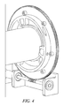
- FIG. 4 shows, in accordance with an embodiment of the invention, the relative positions of the eared flanges and the tangs after coupling.
- Embodiments of the invention relate to blind motorized coupling arrangements in which the light source subsystem of a UV lithography system can be coupled with the scanner subsystem without the need for manual alignment and manual access.
- the blind motorized coupling arrangement includes a source flange having a plurality of eared flanges and a rotating collar having tangs sympathetic to the spacing between the eared flanges of the source flange to allow mating of the two subsystems.
- the implementation discussed herein will have the plurality of eared flanges disposed on the light source subsystem and the rotating collar disposed on the scanner subsystem although one skilled in the art will appreciate that a UV lithography system constructed in accordance with the teachings of the present disclosure may also have the plurality of eared flanges (and associated components as will be discussed herein) disposed on the scanner subsystem and the rotating collar (and associated components as will be discussed herein) disposed on the light source subsystem.
- a face seal surface is provided on a surface of the light source subsystem that faces the scanner subsystem.
- a mating seal surface is provided on the surface that faces the light source subsystem.
- the ears of the plurality of eared flanges are ramped.
- the ramps of the eared flanges push against the tangs of the rotating collar when the rotating collar is rotated.
- the ramping surfaces of the eared flanges thus provide a camming action that urges the face seal surface of the light source subsystem against the mating seal surface of the scanner subsystem to facilitate the desired coupling.
- the rotating collar is rotated using a motor that provides the rotational force to the rotating collar via an appropriate gear assembly (such as a worm gear/worm drive/servo combination, for example).
- the gear assembly permits the motor to be disposed some distance away from the interface region itself, which simplifies the design of the interface region, particular if there are other hardware components that need to be disposed near the interface region.
- the use of the motor eliminates the need for manual access to the interface region.
- one or both of the face seal surface of the light source subsystem and the mating seal surface of the scanner subsystem may be equipped with one or more o-rings.
- the o-ring may be retained, in one or more embodiments, and may be elastomeric or metallic in nature.
- the scanner subsystem is provided with a lead-in stub that is designed to linearly and/or angularly align the two subsystems when the lead-in stub is disposed in a corresponding recess in the light source subsystem.
- the lead-in stub thus provides blind-mate self-centering when the two subsystems are cammed together.
- the tangs of the rotating collar are equipped with bearings (such as tapered needle bearings, for example) to allow the ramped surfaces of the plurality of eared flanges to ride on the bearings when the ramped surfaces of the plurality of eared flanges are cammed against the tangs.
- bearings such as tapered needle bearings, for example
- FIG. 1 shows, in accordance with an embodiment of the invention, a motorized blind coupling arrangement that includes a light source mating flange 100 having a plurality of eared flanges (there are three such eared flanges in the example of FIG. 1 , of which two eared flanges 102 a and 102 b are shown in FIG. 1 ).
- the eared flanges have tapered ramp surfaces such that the thickness of one end of an eared flange (such as end 104 of eared flange 102 b ) is thinner than the other end of the eared flange (such as end 106 of eared flange 102 b ).
- light source mating flange 100 and the plurality of eared flanges ( 102 a / 102 b ) are disposed on a light source output tube 110 .
- the three eared flanges ( 102 a , 102 b , and 102 c ) are shown more clearly in FIG. 2 .
- the tapered ramp feature of each eared flange is also seen.
- eared flange 102 b is shown with a tapered ramp surface 112 , which is created by the difference in thickness between end 104 and 106 .
- Light source output tube 100 includes a scanner-facing surface 114 , a portion of which forms a light source face seal surface 116 .
- Light source face seal surface 116 may be equipped with a retained O-ring, which may be formed of an elastomer material or a metallic material designed for vacuum sealing when light source face seal surface 116 mates against scanner mating seal surface 120 (best seen in FIG. 1 ).
- Rotating collar 124 includes a plurality of tangs 130 a , 130 b , and 130 c .
- the spacing between adjacent ones of tangs 130 a , 130 b , and 130 c is designed to be sufficiently large so as to allowed an eared flange (such as eared flange 102 b ) to be inserted into this inter-tang region (such as the inter-tang region between tangs 130 b and 130 c ).
- rotating collar 124 is rotated to allow the tapered ramp surfaces of the eared flanges to be urged against the tangs, thereby urging light source face seal surface 116 (see FIG. 2 ) against scanner mating seal surface 120 (see FIG. 1 ).
- the rotation of rotating collar 124 is in the clockwise direction to urge tapered ramp surface 112 against, for example, tang 130 b.
- the tangs are provided with bearings to allow the camming action of the tapered ramp surface against the tangs to be accomplished using a rolling motion as rotating collar 124 is rotated.
- the bearings are tapered needle bearings (such as tapered needle bearing 140 ) although other suitable types of bearing may be employed.
- the bearings may be caged as shown in one or more embodiments.
- the scanner subsystem is provided with a tapered lead-in stub 150 .
- the tapered lead-in stub has a tapered cone section 152 designed to fit inside light source output tube 110 .
- the sloping surface of the cone provides linear and/or angular self-centering of tapered lead-in stub 150 with respect to light source output tube 110 .
- Outer diameter 154 of tapered lead-in stub 150 is preferably dimensioned to snugly fit the inner diameter of light source output tube 110 to further accomplish the self-centering.
- a motor 160 is shown in FIG. 1 , representing the motor employed to rotate rotating collar 124 to accomplish the coupling.
- Motor 160 is preferable an electric servo motor although any type of suitable motor may be employed.
- a worm drive/worm gear assembly may be employed to permit motor 160 to rotate rotating collar 124 .
- FIG. 3 shows worm drive 302 having gear disposed on shaft 304 of motor 160 .
- Worm gear 308 is shown coupled to the periphery of the rotating collar.
- the gearing ratio may be anywhere from 1:1 to thousands:1 as desired to provide adequate control and compression force to compress the O-ring seal in order to create and maintain the desired vacuum seal.
- the worm drive/worm gear combination is advantageous in being able to generate the high compression force required to compress, for example, one-time metallic O-ring seals.
- suitable types of gearing mechanism may also be employed if suitable for a specific application.
- a servo motor/worm drive/worm gear combination is employed to rotate rotating collar, other methods for rotating the rotating collar (including for example an) suitable type of hydraulic or electric actuator) may also be employed.
- FIG. 3 also shows the eared flanges as they are mated through the inter-tang spacings and prior to being cammed against the tangs of the rotating collar.
- the tapered ramp surfaces of the eared flanges are not yet cammed against the tapered needle bearings of the tangs of the rotating collar.
- the rotating collar has been rotated counter-clockwise from the position it occupies in FIG. 3 .
- the tapered ramp surfaces of the eared flanges are now pressed against the needle bearings of the tangs of the rotating collar, thereby urging the light source face seal surface against the scanner mating seal surface.
- the gears are shown exposed to facilitate discussion in the example of FIGS. 3 and 4 , the gears may be housed in an enclosure for safety.
- FIG. 1 shows such an enclosure 180 .
- embodiments of the invention facilitate blind-mate self-centering alignment and coupling of the light source subsystem and the scanner subsystem of the UV lithography system.
- the use of the tapered ramp eared flanges and corresponding tangs generates a camming force to urge the two subsystems together when the rotating collar (on which the tangs are disposed) rotates. Since the rotational force is provided by a motor through an appropriate gear assembly, manual access to the interface region is no longer required. Accordingly, space requirement may be reduced in the design of the UV lithography system, particular with respect to space allotment for prior art manual access by the human assembler.
- tapered lead-in stub provides a self-centering capability, both angularly and linearly, to render the alignment process substantially automatic during coupling. Since manual human alignment and coupling is no longer required, the assembly process is more consistent and less dependent upon the skills of the particular human technician who happens to be assigned the assembly task.
- the lead-in stub may employ a sphere for self-centering purposes.
- the number of eared flanges and corresponding cared tangs may be increased as required (e.g., to provide a higher compression force).
- the bearings employed with the tangs of the rotating collar are needle bearings in the illustrated example, other pressure bearing mechanisms (such as roller bearings, ball bearings, etc.) mad also be employed.
- a servo motor/worm drive/worm gear combination is employed to rotate the rotating collar, another suitable actuator (such as a linear actuator or a hydraulic actuator) may be employed.
- an alternative sealing arrangement may be employed.
- An example of such an alternative sealing arrangement is the use of two concentric o-rings sealing against the same face with the region between the o-rings ported and pumped via a rough vacuum pump, thereby providing a pressure differential on both sides of the inner ring.
- the collar may be stationary while the ear flanges are rotated by an appropriate actuator assembly to facilitate the blind motorized alignment and coupling.
Landscapes
- Engineering & Computer Science (AREA)
- General Engineering & Computer Science (AREA)
- Mechanical Engineering (AREA)
- Exposure And Positioning Against Photoresist Photosensitive Materials (AREA)
Abstract
Description
Claims (13)
Priority Applications (1)
| Application Number | Priority Date | Filing Date | Title |
|---|---|---|---|
| US12/210,086 US8061923B2 (en) | 2008-09-12 | 2008-09-12 | Blind motorized coupling arrangements for coupling UV light source subsystem and scanner subsystem in a UV lithography system and methods therefor |
Applications Claiming Priority (1)
| Application Number | Priority Date | Filing Date | Title |
|---|---|---|---|
| US12/210,086 US8061923B2 (en) | 2008-09-12 | 2008-09-12 | Blind motorized coupling arrangements for coupling UV light source subsystem and scanner subsystem in a UV lithography system and methods therefor |
Publications (2)
| Publication Number | Publication Date |
|---|---|
| US20100067983A1 US20100067983A1 (en) | 2010-03-18 |
| US8061923B2 true US8061923B2 (en) | 2011-11-22 |
Family
ID=42007368
Family Applications (1)
| Application Number | Title | Priority Date | Filing Date |
|---|---|---|---|
| US12/210,086 Expired - Fee Related US8061923B2 (en) | 2008-09-12 | 2008-09-12 | Blind motorized coupling arrangements for coupling UV light source subsystem and scanner subsystem in a UV lithography system and methods therefor |
Country Status (1)
| Country | Link |
|---|---|
| US (1) | US8061923B2 (en) |
Cited By (7)
| Publication number | Priority date | Publication date | Assignee | Title |
|---|---|---|---|---|
| US20110126474A1 (en) * | 2009-12-01 | 2011-06-02 | Lockheed Martin Corpration | Bulkhead sealing mechanism |
| US20140178126A1 (en) * | 2010-08-26 | 2014-06-26 | Rotite Limited | Device for and Method of Connecting Two Items Together |
| US9961966B2 (en) * | 2013-11-14 | 2018-05-08 | Timothy J. Ryan | System and method for a detachable button |
| US10383409B2 (en) * | 2013-07-11 | 2019-08-20 | Fidlock Gmbh | Closure device |
| US10473302B2 (en) * | 2017-06-29 | 2019-11-12 | Lite-On Technology Corporation | Illumination device and installing method thereof |
| US11154106B2 (en) * | 2014-04-01 | 2021-10-26 | Bell Sports, Inc. | Locking liner for helmet |
| US20240003407A1 (en) * | 2020-12-02 | 2024-01-04 | Sacs Aerospace Gmbh | Coupling arrangement |
Families Citing this family (3)
| Publication number | Priority date | Publication date | Assignee | Title |
|---|---|---|---|---|
| IT1400559B1 (en) * | 2010-06-28 | 2013-06-14 | V I C Viterie Italia Centrale S R L | EQUIPMENT FOR THE CONSTRUCTION OF THE STABLE AND QUICK FIXING OF A PULLEY TO A RESPECTIVE SHAFT |
| US9095957B2 (en) | 2011-09-16 | 2015-08-04 | Wolf Robotics, Llc | Rotary actuated axial clamp |
| FR3014974B1 (en) * | 2013-12-16 | 2016-01-01 | Leroy Somer Moteurs | COUPLING SYSTEM OF A DRIVE MACHINE WITH A DRIVEN MACHINE |
Citations (7)
| Publication number | Priority date | Publication date | Assignee | Title |
|---|---|---|---|---|
| US4486918A (en) * | 1983-04-29 | 1984-12-11 | Motorola, Inc. | Snap action removable knob |
| GB2187820A (en) * | 1986-03-15 | 1987-09-16 | Gelenkwellenbau Gmbh | Shaft coupling for hookes joint |
| US4990022A (en) * | 1988-03-07 | 1991-02-05 | Honda Giken Kogyo Kabushiki Kaisha | Robot hand coupling assembly |
| US20020110388A1 (en) * | 2001-02-02 | 2002-08-15 | Canon Kabushiki Kaisha | Process cartridge, electrophotographic photosensitive drum, electrophotographic image forming apparatus and color electrophotographic image forming apparatus |
| US7264391B2 (en) * | 2002-11-14 | 2007-09-04 | Koninklijke Philips Electronics, N.V. | System and method for fixing a lamp in a reflector housing |
| US7603059B2 (en) * | 2005-01-26 | 2009-10-13 | Kyocera Mita Corporation | Shaft coupling, and function unit drive device for an image forming device comprising the same |
| US7641517B2 (en) * | 2008-02-12 | 2010-01-05 | Bjb Gmbh & Co. Kg | Keyed socket and lamp base |
-
2008
- 2008-09-12 US US12/210,086 patent/US8061923B2/en not_active Expired - Fee Related
Patent Citations (7)
| Publication number | Priority date | Publication date | Assignee | Title |
|---|---|---|---|---|
| US4486918A (en) * | 1983-04-29 | 1984-12-11 | Motorola, Inc. | Snap action removable knob |
| GB2187820A (en) * | 1986-03-15 | 1987-09-16 | Gelenkwellenbau Gmbh | Shaft coupling for hookes joint |
| US4990022A (en) * | 1988-03-07 | 1991-02-05 | Honda Giken Kogyo Kabushiki Kaisha | Robot hand coupling assembly |
| US20020110388A1 (en) * | 2001-02-02 | 2002-08-15 | Canon Kabushiki Kaisha | Process cartridge, electrophotographic photosensitive drum, electrophotographic image forming apparatus and color electrophotographic image forming apparatus |
| US7264391B2 (en) * | 2002-11-14 | 2007-09-04 | Koninklijke Philips Electronics, N.V. | System and method for fixing a lamp in a reflector housing |
| US7603059B2 (en) * | 2005-01-26 | 2009-10-13 | Kyocera Mita Corporation | Shaft coupling, and function unit drive device for an image forming device comprising the same |
| US7641517B2 (en) * | 2008-02-12 | 2010-01-05 | Bjb Gmbh & Co. Kg | Keyed socket and lamp base |
Cited By (12)
| Publication number | Priority date | Publication date | Assignee | Title |
|---|---|---|---|---|
| US20110126474A1 (en) * | 2009-12-01 | 2011-06-02 | Lockheed Martin Corpration | Bulkhead sealing mechanism |
| US8851786B2 (en) * | 2009-12-01 | 2014-10-07 | Lockhead Martin Corporation | Bulkhead sealing mechanism |
| US20140178126A1 (en) * | 2010-08-26 | 2014-06-26 | Rotite Limited | Device for and Method of Connecting Two Items Together |
| US9562553B2 (en) * | 2010-08-26 | 2017-02-07 | Rotite Limited | Device for and method of connecting two items together |
| US10180153B2 (en) | 2010-08-26 | 2019-01-15 | Rotite Limited | Device for and method of connecting two items together |
| US10383409B2 (en) * | 2013-07-11 | 2019-08-20 | Fidlock Gmbh | Closure device |
| US9961966B2 (en) * | 2013-11-14 | 2018-05-08 | Timothy J. Ryan | System and method for a detachable button |
| US11154106B2 (en) * | 2014-04-01 | 2021-10-26 | Bell Sports, Inc. | Locking liner for helmet |
| US11998079B2 (en) | 2014-04-01 | 2024-06-04 | Bell Sports, Inc. | Locking liner for helmet |
| US10473302B2 (en) * | 2017-06-29 | 2019-11-12 | Lite-On Technology Corporation | Illumination device and installing method thereof |
| US20240003407A1 (en) * | 2020-12-02 | 2024-01-04 | Sacs Aerospace Gmbh | Coupling arrangement |
| US12546381B2 (en) * | 2020-12-02 | 2026-02-10 | Sacs Aerospace Gmbh | Coupling arrangement |
Also Published As
| Publication number | Publication date |
|---|---|
| US20100067983A1 (en) | 2010-03-18 |
Similar Documents
| Publication | Publication Date | Title |
|---|---|---|
| US8061923B2 (en) | Blind motorized coupling arrangements for coupling UV light source subsystem and scanner subsystem in a UV lithography system and methods therefor | |
| US10162146B2 (en) | Opto-mechanical apparatus adapted for mounting optical elements with small cross sections | |
| US8033549B2 (en) | Mechanical seal | |
| US8177436B2 (en) | Bearing anti creep device and method | |
| JP5960684B2 (en) | Sleeve seal assembly and rotary valve having sleeve seal assembly | |
| DE602004010346T2 (en) | Exhaust gas seal for a turbocharger | |
| KR101606436B1 (en) | Debris mitigation device with rotating foil trap and drive assembly | |
| JP2007321764A (en) | Compressor, turbine engine component, assembling method for compressor, and assembly component of disk and blade | |
| US20130062832A1 (en) | Flow machine, slide ring seal thereof, body part for said slide ring seal and method of fastening said slide ring seal to said flow machine | |
| CA2987833C (en) | Mechanical seal arrangement with a release protection device | |
| US9377060B1 (en) | Ball ramp actuator | |
| CN111801522B (en) | Rotary motion sealing device | |
| DE60207675T2 (en) | Mechanical seal | |
| CN107667206B (en) | High-reliability high-flow redundancy trip block | |
| US20090174149A1 (en) | Mechanical seal device | |
| EP3318763B1 (en) | Vacuum seal, dual seal, vacuum system and vacuum pump | |
| JP2022166306A (en) | BALL SCREW, BALL SCREW MANUFACTURING METHOD, AND TEMPORARY NUT | |
| US20220389999A1 (en) | Differential and thrust washer therefor | |
| CN213655672U (en) | Sealing mechanism and gear box | |
| EP3327293B1 (en) | Vacuum pump having multiple inlets | |
| US20080174073A1 (en) | Method for securing a cartridge mechanical face seal to a sleeve | |
| US20260071668A1 (en) | Roller screw drive and method for assembling a roller screw drive | |
| CN105829726A (en) | Thrust Bearing For Centrifugal Pumps | |
| JP2006105370A (en) | Sealing device and bearing device | |
| JP2006077835A (en) | Sealing device |
Legal Events
| Date | Code | Title | Description |
|---|---|---|---|
| AS | Assignment |
Owner name: CYMER, INC.,CALIFORNIA Free format text: ASSIGNMENT OF ASSIGNORS INTEREST;ASSIGNOR:SIMMONS, RODNEY D.;REEL/FRAME:021530/0695 Effective date: 20080910 Owner name: CYMER, INC., CALIFORNIA Free format text: ASSIGNMENT OF ASSIGNORS INTEREST;ASSIGNOR:SIMMONS, RODNEY D.;REEL/FRAME:021530/0695 Effective date: 20080910 |
|
| FEPP | Fee payment procedure |
Free format text: PAYOR NUMBER ASSIGNED (ORIGINAL EVENT CODE: ASPN); ENTITY STATUS OF PATENT OWNER: LARGE ENTITY |
|
| AS | Assignment |
Owner name: CYMER, LLC, CALIFORNIA Free format text: MERGER;ASSIGNOR:CYMER, INC.;REEL/FRAME:032420/0153 Effective date: 20130530 |
|
| AS | Assignment |
Owner name: ASML NETHERLANDS B.V., NETHERLANDS Free format text: ASSIGNMENT OF ASSIGNORS INTEREST;ASSIGNOR:CYMER, LLC;REEL/FRAME:032860/0748 Effective date: 20140106 |
|
| REMI | Maintenance fee reminder mailed | ||
| LAPS | Lapse for failure to pay maintenance fees | ||
| STCH | Information on status: patent discontinuation |
Free format text: PATENT EXPIRED DUE TO NONPAYMENT OF MAINTENANCE FEES UNDER 37 CFR 1.362 |
|
| STCH | Information on status: patent discontinuation |
Free format text: PATENT EXPIRED DUE TO NONPAYMENT OF MAINTENANCE FEES UNDER 37 CFR 1.362 |
|
| FP | Lapsed due to failure to pay maintenance fee |
Effective date: 20151122 |