US8052228B2 - Movable axle guard for a compactor wheel - Google Patents
Movable axle guard for a compactor wheel Download PDFInfo
- Publication number
- US8052228B2 US8052228B2 US11/328,391 US32839106A US8052228B2 US 8052228 B2 US8052228 B2 US 8052228B2 US 32839106 A US32839106 A US 32839106A US 8052228 B2 US8052228 B2 US 8052228B2
- Authority
- US
- United States
- Prior art keywords
- rim
- axle
- hub
- recess
- axle guard
- Prior art date
- Legal status (The legal status is an assumption and is not a legal conclusion. Google has not performed a legal analysis and makes no representation as to the accuracy of the status listed.)
- Expired - Fee Related, expires
Links
Images


Classifications
-
- B—PERFORMING OPERATIONS; TRANSPORTING
- B60—VEHICLES IN GENERAL
- B60S—SERVICING, CLEANING, REPAIRING, SUPPORTING, LIFTING, OR MANOEUVRING OF VEHICLES, NOT OTHERWISE PROVIDED FOR
- B60S1/00—Cleaning of vehicles
- B60S1/62—Other vehicle fittings for cleaning
- B60S1/66—Other vehicle fittings for cleaning for cleaning vehicle exterior
- B60S1/68—Other vehicle fittings for cleaning for cleaning vehicle exterior for freeing wheels or tyres from foreign matter, e.g. wheel scrapers
Definitions
- the present invention relates to compaction machines, such as those used to compact landfills, more particularly, to the compactor wheels on such a compaction machine and, even more particularly, to a compactor wheel having a movable axle guard.
- Compaction machines are used to compact landfill sites, garbage dumps and other such locations. These machines typically include a self-propelled vehicle having four large wheels made of steel. Each wheel has a hub mounted to one end of an axle and a rim disposed around and radially out from the hub. The rim typically includes a plurality of cleats mounted thereon.
- Waste materials such as steel cable, wire, rope and the like have a particularly detrimental effect. Such refuse tends to wrap around the axles of the compaction machine and become trapped between the wheel and a side wall of the compaction machine, increasing the corresponding frictional forces therebetween.
- Increasing the friction between the wheel and the compaction machine increases the load on the wheel propulsion system (e.g., an internal combustion engine) and reduces the life of the compaction machine.
- the wheel propulsion system e.g., an internal combustion engine
- Such increased frictional forces can cause the compaction wheels to wear to the point of requiring repair or even replacement of the wheels.
- Such wear related repairs can be very costly, and replacement wheels are very expensive.
- a compactor wheel mountable on an axle of a compaction machine.
- the compactor wheel comprises a hub mountable to an axle of a compaction machine; a rim mounted to the hub, the rim having a face; a plurality of compaction cleats mounted to the face of the rim; structure for defining a recess; and an axle guard positioned within the recess and being capable of moving within the recess during rotation of the compactor wheel.
- the recess may be annular in shape.
- the structure may include an inner base having a first dimension.
- the axle guard has an opening of a second dimension which is preferably greater than the first dimension.
- the axle guard may comprise a ring-shaped plate having inner and outer diameters, where the inner diameter defines the second dimension.
- the recess may have a depth equal to a third dimension and the inner diameter of the axle guard ring-shaped plate may be equal to or less than an outer diameter of the rim minus the third dimension.
- the structure for defining a recess may comprise: a reinforcement member coupled to the hub; a plurality of gussets coupled to the hub; a first ring-shaped plate fixedly coupled to the reinforcement member; and a second ring-shaped plate spaced from the first plate.
- the gussets may be coupled to the hub by being bolted to side plates which are fixedly coupled to the hub. Alternatively, the gussets may be welded directly to the hub.
- the rim has an outer diameter and the axle guard has an outer diameter which is greater than the rim outer diameter.
- the axle guard may move within the recess in a direction generally transverse to a longitudinal axis of the hub.
- a first portion of an outer surface of the axle guard lies in a common horizontal plane with a first portion of the rim face when the rim face first portion is positioned directly adjacent to a surface along which the wheel moves and a second portion of the axle guard outer surface positioned diametrically opposed to the first portion of the axle guard outer surface is positioned above a second portion of the rim face positioned diametrically opposed to the first portion of the rim face.
- the axle guard may be positioned near an inner edge of the rim.
- the axle guard may be positioned between first and second circumferential rows of the compaction cleats, wherein the rows are transversely spaced apart from one another.
- a compactor wheel mountable on an axle of a compaction machine comprises: a hub mountable to an axle of a compaction machine; a rim mounted to the hub, the rim having a face; a plurality of compaction cleats mounted to the face of the rim; an axle guard movable relative to the rim during rotation of the compactor wheel; and structure for coupling the axle guard to at least one of the hub and the rim.
- the coupling structure may comprise first and second plates defining a recess for receiving the axle guard and a plurality of pins extending between the plates and passing through corresponding openings in the axle guard.
- the axle guard may comprises a ring-shaped plate having inner and outer diameters.
- the ring-shaped plate may include the axle guard openings, wherein each of the axle guard openings has a diameter which is substantially greater than an outer diameter of a corresponding pin such that the ring-shaped plate is capable of moving within the recess.
- FIG. 1 is a side view of a compactor wheel including a movable axle guard constructed in accordance with a first embodiment of the present invention
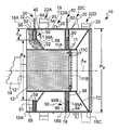
- FIG. 2 is a cross-sectional view of a compactor wheel including two movable guards constructed in accordance with a first embodiment of the present invention
- FIG. 2A is a side view of an axle guard ring shaped plate forming part of the wheel illustrated in FIG. 2 ;
- FIG. 3 is a perspective view of a compactor wheel including a single movable guard constructed in accordance with a first embodiment of the present invention
- FIG. 4 is a cross-sectional view of a compactor wheel including a movable axle guard constructed in accordance with a second embodiment of the present invention
- FIG. 4A is a side view of an axle guard ring shaped plate forming part of the wheel illustrated in FIG. 4 ;
- FIG. 4B is an enlarged view of structure defining a recess in which an axle guard ring shaped plate is provided in the compactor wheel illustrated in FIG. 4 ;
- FIG. 5 is a side view of a compactor wheel including a movable guard constructed in accordance with a second embodiment of the present invention
- FIG. 6 is a perspective view of the compactor wheel of FIG. 4 ;
- FIG. 7 is a side view of a compactor wheel including a movable guard constructed in accordance with a third embodiment of the present invention.
- FIG. 8 is a cross-sectional view of a compactor wheel including a movable guard constructed in accordance with a third embodiment of the present invention.
- a compactor wheel 10 constructed in accordance with a first embodiment of the present invention is shown mounted on an axle 12 (the axle is not shown in FIGS. 1 and 3 ) of a compaction machine 14 , such as those disclosed in U.S. Pat. Nos. 3,340,783; 4,530,620; and 5,358,355, which are incorporated by reference herein, in their entirety.
- the wheel 10 includes a hub 11 comprising a substantially cylindrical portion 11 A and a ring-shaped plate 11 B fixed within the cylindrical portion 11 A and including a plurality of holes for receiving bolts 11 C to allow the hub 11 to be coupled to the axle 12 .
- the rim 18 includes an outer face or surface 19 on which a plurality of cleats 20 (not shown in FIG. 3 ) are mounted, such as by welding or any other suitable technique.
- An axle guard 30 is provided to form a barrier to help prevent cable, rope, wire and other refuse and debris from moving inward along the wheel 10 and subsequently wrapping around the axle 12 of the compaction machine 14 , see FIG. 2 .
- the axle guard 30 comprises a first axle guard 30 .
- the axle guard 30 oscillates and, as such, also functions to knock or force off cable, rope, wire and the like which might be entangled or wrapped about one or more cleats 20 .
- the axle guard 30 comprises a ring-shaped plate 32 having an inner diameter D I , an outer diameter D O and a width W R equal to the outer diameter D O minus the inner diameter D I , see FIG. 2A .
- the outer diameter D O of the ring-shaped plate 32 is larger than an outer diameter D R of the rim 18 .
- the plate 32 is preferably formed from a metal, such as steel.
- the axle guard 30 is located within an annular recess 40 defined by structure 50 forming part of the wheel 10 , see FIG. 2 .
- the recess 40 is preferably positioned near an inner edge 10 A of the wheel 10 , see FIG. 2 .
- the recess 40 has a depth L D from the outer face 19 of the rim 18 which is equal to a third dimension.
- the structure 50 includes an inner base 51 having a diameter D B .
- the inner diameter D I of the axle guard ring-shaped plate 32 is greater than the diameter D B of the inner base 51 so as to allow the axle guard 30 to move, e.g., oscillate, within the recess 40 as the wheel 10 rotates on a surface S, see FIG. 1 , such as a surface of a landfill.
- the axle guard 30 may move freely within the recess 40 in a direction generally transverse to a longitudinal axis A H of the hub 11 , see FIG. 2 . It is also preferred that: D I ⁇ D R ⁇ L D W R ⁇ L D
- D I the inner diameter of the axle guard ring-shaped plate 32 ;
- D R the outer diameter of the rim 18 ;
- W R the width of the ring-shaped plate 32 ;
- L D the third dimension or the depth of the recess 40 .
- a first portion 34 A of an outer surface 34 of the axle guard 30 is positioned in a common horizontal plane H P with a first portion 19 A of the rim face 19 when the rim face first portion 19 A is positioned directly adjacent to the surface S, see FIG. 1 .
- a second portion 34 B of the axle guard outer surface 34 positioned diametrically opposed to the first portion 34 A of the axle guard outer surface 34 , is positioned above, i.e., is spaced from, a second portion 19 B of the rim face 19 , which is positioned diametrically opposed to the first portion 19 A of the rim face 19 , see FIG. 1 .
- the surface S will force the axle guard 32 upward such that the portion of the axle guard outer surface 34 located directly adjacent to the surface S, illustrated in FIG. 1 and described above as the first portion 34 A, will preferably not extend beyond, i.e., below, the plane H P in which the portion of the rim face 19 positioned directly adjacent to the surface S, which portion is illustrated in FIG. 1 and described above as the first portion 19 A, is located. Because the portion of the axle guard outer surface 34 located directly adjacent to the surface S does not extend beyond the rim face 19 in the illustrated embodiment, wear of the axle guard 30 at its outer surface 34 via contact with the surface S is substantially reduced.
- the amount of the axle guard 30 extending beyond the rim face 19 varies, with the least amount being exposed at a six o'clock position, as viewed in FIG. 1 , and the greatest amount being exposed at a twelve o'clock position.
- the greatest distance between a portion of the axle guard outer surface 34 and an adjacent portion of the rim face 19 occurs between the second portion 34 B of the axle guard outer surface 34 and the second portion 19 B of the rim face 19 .
- the second portion 34 B of the axle guard outer surface 34 may extends above the second portion 19 B of the rim face 19 by an amount equal to about 0.1 to about 1.5 times the height of the largest cleat 20 , i.e., the cleat 20 with the greatest height above the rim face 19 .
- the structure 50 defining the recess 40 comprises a first cone-shaped member 52 , first and second ring-shaped plates 54 and 56 , a plurality of gussets 58 and a plurality of coupling bars 59 , all of which may be formed from a metal, such as steel.
- the first cone-shaped member 52 is weldably or otherwise fixedly coupled to the hub 11 and to the first ring-shaped reinforcement plate 54 .
- the first ring-shaped reinforcement plate 54 in addition to being coupled to the cone-shaped member 52 , is also coupled to the rim 18 and the coupling bars 59 .
- the second ring-shaped plate 56 is spaced from the first plate 54 , and fixedly coupled to the rim 18 and the plurality of coupling bars 59 .
- the coupling bars 59 extend between and, as noted above, are coupled to the first and second plates 54 and 56 .
- the coupling bars 59 and plate-receiving portions 58 A of the gussets 58 define the innerbase 51 .
- the gussets 58 are weldably coupled to the hub 11 and the rim 18 and may be coupled to one or both of the first and second plates 54 and 56 .
- Positioned within the recess 40 on opposite sides of the axle guard 30 and adjacent to the first and second plates 54 and 56 are polymeric or abrasion-resistant metal rings 60 and 62 , which function to prevent wear during movement of the axle guard 30 within the recess 40 .
- a second cone-shaped member 72 which is weldably coupled between the hub 11 and the rim 18 .
- a second axle guard 80 is provided (not shown in FIGS. 1 and 3 ), which is formed from a ring-shaped plate 82 which is similar in shape and size to the ring-shaped plate 32 defining the first axle guard 30 .
- the second axle guard 80 is positioned in a recess 90 defined by structure 92 comprising first and second ring shaped side plates 94 and 96 and a ring-shaped base plate 98 , all of which may be formed from a metal.
- the side plates 94 and 96 are fixedly coupled respectively to the third and second sections 18 C and 18 B of the rim 18 .
- the base plate 98 is fixedly coupled to the hub 11 and is fixedly coupled to the plates 94 and 96 .
- axle guard 80 Positioned within the recess 90 on opposite sides of the axle guard 80 and adjacent to the first and second plates 94 and 96 are polymeric or abrasion-resistant metal rings 99 A and 99 B, which function to prevent wear during movement of the axle guard 80 within the recess 90 .
- the second axle guard 80 moves within its recess 90 in the same manner in which the first axle guard 30 moves within its recess 40 .
- the cleats 20 are arranged in first, second, third and fourth circumferential rows 22 A- 22 D, wherein the rows 22 A- 22 D are spaced apart transversely.
- the second axle guard 80 is positioned between the second and third rows 22 B and 22 C of the cleats 20 .
- the second axle guard 80 functions to remove or knock off cable, wire, rope, and the like which might be wrapped around or caught on an adjacent cleat 20 .
- the second axle guard 80 also functions to remove dirt, rocks, and other debris which accumulates in the space between the rows 22 B and 22 C on opposite sides of the second axle guard 80 .
- one or more additional axle guards may be provided between the remaining rows of cleats, e.g., between the third and fourth rows 22 C and 22 D of cleats 20 .
- FIGS. 4-6 A compactor wheel 100 constructed in accordance with a second embodiment of the present invention is illustrated in FIGS. 4-6 , where like reference numerals indicate like elements.
- the wheel 100 includes a hub 11 comprising a substantially cylindrical portion 11 A and a ring-shaped plate 11 B fixed within the cylindrical portion 11 A and including a plurality of holes for receiving bolts (not shown in FIGS. 4-6 ) to allow the hub 11 to be secured to an axle (not shown in FIGS. 4-6 ).
- a rim 118 is mounted around the hub 11 .
- the rim 118 includes an outer face or surface 119 on which a plurality of cleats 20 (only shown in FIG. 4 ) are mounted, such as by welding or any other suitable technique.
- the axle guard 130 comprises a ring-shaped plate 132 having an inner diameter D I2 , an outer diameter D O2 and a width W R2 equal to the outer diameter D O2 minus the inner diameter D I2 , see FIG. 4A .
- the outer diameter D O2 of the ring-shaped plate 32 is larger than the outer diameter D R of the rim 118 mounted about the hub 11 .
- the plate 132 includes a plurality of openings 134 , which are adapted to receive pins 135 , as discussed below.
- the plate 132 is preferably formed from a metal, such as steel.
- the axle guard 130 is located within an annular recess 140 defined by structure 150 forming part of the wheel 10 , see FIG. 4B .
- the recess 140 is positioned near an inner edge 110 A of the wheel.
- the recess 140 is defined by first and second ring-shaped plates 152 and 154 .
- the first plate 152 is weldably coupled to the rim 118 .
- Extending from the first plate 152 are the pins 135 , which are spaced apart from one another along an outer periphery of the first plate 152 .
- the pins 135 are weldably or otherwise fixedly coupled to the first plate 152 .
- the axle guard ring-shaped plate 132 is mounted adjacent to the first plate 152 such that the pins 135 extend through corresponding openings 134 in the plate 132 .
- the second ring-shaped plate 154 is mounted over the axle guard ring-shaped plate 132 and coupled to the first plate 132 via bolts 134 A which are threadedly received by the pins 135 .
- polymeric or abrasion-resistant plates may be positioned on opposing sides of the axle guard 130 .
- the diameter of the openings 134 is larger than the diameter of the pins 135 so as to allow the axle guard 130 to move, e.g., oscillate, within the recess 140 as the wheel 100 rotates on a surface S, see FIG. 5 .
- the axle guard 130 may move freely within the recess 140 in a direction generally transverse to a longitudinal axis A H of the hub 11 , see FIG. 4 .
- the openings 134 and pins 135 be positioned and sized so that as the wheel 100 rotates along the surface S, the surface S will force the axle guard 130 upward such that a first portion 136 A of an outer surface 136 of the axle guard 130 is positioned in a common horizontal plane H P with a first portion 119 A of the rim face 119 when the rim face first portion 119 A is positioned directly adjacent to the surface S.
- the amount of the axle guard 130 extending beyond the rim face 119 varies, with the least amount being exposed at a six o'clock position, as viewed in FIG. 5 , and the greatest amount being exposed at a twelve o'clock position.
- the greatest distance between a portion of the axle guard outer surface 136 and an adjacent portion of the rim face 119 occurs between a second portion 136 B of the axle guard outer surface 136 and a second portion 1 19 B of the rim face 119 , which rim face second portion 119 B is diametrically opposed to the rim face first portion 119 A.
- the second portion 136 B of the axle guard outer surface 136 may extends above the second portion 119 B of the rim face 119 by an amount equal to about 0.1 to about 1.5 times the height of the largest cleat 20 , i.e., the cleat 20 with the greatest height above the rim face 119 .
- FIGS. 7 and 8 A compactor wheel 200 constructed in accordance with a third embodiment of the present invention is illustrated in FIGS. 7 and 8 , where like reference numerals indicate like elements.
- the wheel 200 includes a hub 11 comprising a substantially cylindrical portion 11 A and a ring-shaped plate 11 B fixed within the cylindrical portion 11 A and including a plurality of holes for receiving bolts to allow the hub 11 to be secured to an axle (not shown in FIGS. 7 and 8 ).
- a rim 18 is mounted around the hub 11 and is constructed in generally the same manner as the rim 18 illustrated in the FIG. 2 embodiment.
- the rim 18 includes an outer face or surface 19 on which a plurality of cleats 20 are mounted, such as by welding or any other suitable technique.
- An axle guard 230 is provided which functions in a similar manner to the axle guard 30 discussed above.
- the axle guard 230 is formed from a ring-shaped plate 232 which is similar in shape and size to the ring-shaped plate 32 defining the first axle guard 30 .
- the axle guard 230 is positioned in a recess 240 .
- the structure 250 defining the recess 240 comprises a first cone-shaped member 252 , first and second ring-shaped reinforcement plates 254 and 256 , a plurality of gussets 258 and pairs of first and second reinforcement side plates 259 A and 259 B, all of which may be formed from a metal, such as steel.
- the first and second side plates 259 A and 259 B are weldably coupled to the hub 11 and the first cone-shaped member 252 .
- the first cone-shaped member 252 in addition to being coupled to the side plates 259 A and 259 B, is also fixedly coupled to the hub 11 and to the first ring-shaped reinforcement plate 254 .
- the first ring-shaped reinforcement plate 254 in addition to being coupled to the cone-shaped member 252 , is also coupled to the rim second section 18 B and may be coupled to the side plates 259 A and 259 B.
- the hub 11 , rim second section 18 B, side plates 259 A and 259 B, member 252 and plate 254 define a first assembly 300 .
- the second ring-shaped plate 256 is fixedly coupled to the gussets 258 and the rim first section 18 A.
- the gussets 58 in addition to being coupled to the plate 256 , are also coupled to the rim first section 18 A.
- the second ring-shaped plate 256 , the gussets 258 and the rim first section 18 A define a second assembly 310 .
- first and second polymeric or abrasion-resistant metal rings 60 and 62 Positioned within the recess 240 on opposite sides of the axle guard 230 and adjacent to the first and second plates 254 and 256 are first and second polymeric or abrasion-resistant metal rings 60 and 62 , which function to prevent wear during movement of the axle guard 230 within the recess 240 .
- the first and second assemblies 300 and 310 , the axle guard 230 and the rings 60 and 62 are assembled as follows.
- the first ring 60 is positioned adjacent to the first reinforcement plate 254 .
- the axle guard 230 is then positioned adjacent to the first ring 60 with the second ring 62 being placed adjacent to the axle guard 230 on a side opposite to the side positioned adjacent to the ring 60 .
- the second assembly 310 is positioned adjacent to the first assembly 300 such that the second reinforcement plate 256 is positioned adjacent to the second ring 62 .
- Bolts 259 C are passed through the first and second side plates 259 A and 259 B and the gussets 258 to secure the first and second assemblies 300 and 310 together.
- the axle guard 230 moves within its recess 240 in the same manner in which the first axle guard 30 moves within its recess 40 .
Landscapes
- Engineering & Computer Science (AREA)
- Mechanical Engineering (AREA)
- Investigation Of Foundation Soil And Reinforcement Of Foundation Soil By Compacting Or Drainage (AREA)
Abstract
Description
D I ≦D R −L D
WR≦LD
Claims (10)
Priority Applications (2)
| Application Number | Priority Date | Filing Date | Title |
|---|---|---|---|
| US11/328,391 US8052228B2 (en) | 2005-04-27 | 2006-01-09 | Movable axle guard for a compactor wheel |
| US29/351,363 USD615563S1 (en) | 2006-01-09 | 2009-12-04 | Movable axle guard for a compactor wheel |
Applications Claiming Priority (2)
| Application Number | Priority Date | Filing Date | Title |
|---|---|---|---|
| US67524905P | 2005-04-27 | 2005-04-27 | |
| US11/328,391 US8052228B2 (en) | 2005-04-27 | 2006-01-09 | Movable axle guard for a compactor wheel |
Related Child Applications (1)
| Application Number | Title | Priority Date | Filing Date |
|---|---|---|---|
| US29/351,363 Continuation USD615563S1 (en) | 2006-01-09 | 2009-12-04 | Movable axle guard for a compactor wheel |
Publications (2)
| Publication Number | Publication Date |
|---|---|
| US20060244311A1 US20060244311A1 (en) | 2006-11-02 |
| US8052228B2 true US8052228B2 (en) | 2011-11-08 |
Family
ID=37233765
Family Applications (1)
| Application Number | Title | Priority Date | Filing Date |
|---|---|---|---|
| US11/328,391 Expired - Fee Related US8052228B2 (en) | 2005-04-27 | 2006-01-09 | Movable axle guard for a compactor wheel |
Country Status (1)
| Country | Link |
|---|---|
| US (1) | US8052228B2 (en) |
Families Citing this family (5)
| Publication number | Priority date | Publication date | Assignee | Title |
|---|---|---|---|---|
| USD615563S1 (en) * | 2006-01-09 | 2010-05-11 | Terra Compactor Wheel Corp. | Movable axle guard for a compactor wheel |
| US8523291B2 (en) * | 2010-03-19 | 2013-09-03 | Caterpillar Inc. | Compactor wheel tip |
| USD654513S1 (en) * | 2010-03-19 | 2012-02-21 | Caterpillar, Inc. | Wheel segment |
| USD744010S1 (en) * | 2014-04-28 | 2015-11-24 | Bernard Mccartney Limited | Wheel cleat guard |
| US20200115872A1 (en) * | 2018-10-15 | 2020-04-16 | Caterpillar Inc. | Modular steel wireguard with gussets |
Citations (16)
| Publication number | Priority date | Publication date | Assignee | Title |
|---|---|---|---|---|
| US1182662A (en) * | 1915-11-30 | 1916-05-09 | Maurice Samuel Eby | Tractor-wheel. |
| US1305303A (en) * | 1919-06-03 | Tractor-wheel | ||
| US3340783A (en) | 1965-07-12 | 1967-09-12 | West Coast Alloys Co | Compactor lug having replaceable cap |
| US4530620A (en) | 1983-02-17 | 1985-07-23 | Bernard Mccartney Limited | Landfill compactor vehicles |
| US5209050A (en) * | 1991-11-04 | 1993-05-11 | Tracy Carrigan | Mower wheel assembly |
| US5330260A (en) * | 1992-09-09 | 1994-07-19 | Ernie Freeman | Wheel cleaning system |
| US5358355A (en) | 1993-04-23 | 1994-10-25 | Terra Environmental Group Inc. | Compaction wheel cleat |
| USD379630S (en) | 1994-10-03 | 1997-06-03 | Terra Compactor Wheel Corp. | Compaction wheel cleat |
| US5676493A (en) | 1996-02-02 | 1997-10-14 | Terra Compactor Wheel Corp. | Compaction machine wheel |
| US5687799A (en) * | 1996-08-12 | 1997-11-18 | Caterpillar Inc. | Wheel assembly for a compacting machine |
| US5769507A (en) | 1995-10-19 | 1998-06-23 | Terra Compactor Wheel Corp. | Compactor wheel axle guard system |
| US6042192A (en) | 1997-07-30 | 2000-03-28 | Brockway; Robert J. | Self-adjusting compactor wheel |
| US6273516B1 (en) | 1997-07-30 | 2001-08-14 | Robert J. Brockway | Self-adjusting compactor wheel and method of use |
| US20040012244A1 (en) * | 2002-07-17 | 2004-01-22 | Waterman Terry M. | Device to protect vehicle wheels and axles from debris |
| US6913289B2 (en) | 2002-06-13 | 2005-07-05 | Robert John Brockway | Front frame upper-wheel wings and rear catwalk, fan and engine guard for trash compactor machines |
| US20050263976A1 (en) | 2002-06-14 | 2005-12-01 | Brockway Robert J | Swing-away stair assembly |
Family Cites Families (2)
| Publication number | Priority date | Publication date | Assignee | Title |
|---|---|---|---|---|
| US379630A (en) * | 1888-03-20 | Oscillating steam-engine | ||
| SE518546C2 (en) * | 1999-08-30 | 2002-10-22 | Stendals Elek Ska Ab | End plate for doors |
-
2006
- 2006-01-09 US US11/328,391 patent/US8052228B2/en not_active Expired - Fee Related
Patent Citations (16)
| Publication number | Priority date | Publication date | Assignee | Title |
|---|---|---|---|---|
| US1305303A (en) * | 1919-06-03 | Tractor-wheel | ||
| US1182662A (en) * | 1915-11-30 | 1916-05-09 | Maurice Samuel Eby | Tractor-wheel. |
| US3340783A (en) | 1965-07-12 | 1967-09-12 | West Coast Alloys Co | Compactor lug having replaceable cap |
| US4530620A (en) | 1983-02-17 | 1985-07-23 | Bernard Mccartney Limited | Landfill compactor vehicles |
| US5209050A (en) * | 1991-11-04 | 1993-05-11 | Tracy Carrigan | Mower wheel assembly |
| US5330260A (en) * | 1992-09-09 | 1994-07-19 | Ernie Freeman | Wheel cleaning system |
| US5358355A (en) | 1993-04-23 | 1994-10-25 | Terra Environmental Group Inc. | Compaction wheel cleat |
| USD379630S (en) | 1994-10-03 | 1997-06-03 | Terra Compactor Wheel Corp. | Compaction wheel cleat |
| US5769507A (en) | 1995-10-19 | 1998-06-23 | Terra Compactor Wheel Corp. | Compactor wheel axle guard system |
| US5676493A (en) | 1996-02-02 | 1997-10-14 | Terra Compactor Wheel Corp. | Compaction machine wheel |
| US5687799A (en) * | 1996-08-12 | 1997-11-18 | Caterpillar Inc. | Wheel assembly for a compacting machine |
| US6042192A (en) | 1997-07-30 | 2000-03-28 | Brockway; Robert J. | Self-adjusting compactor wheel |
| US6273516B1 (en) | 1997-07-30 | 2001-08-14 | Robert J. Brockway | Self-adjusting compactor wheel and method of use |
| US6913289B2 (en) | 2002-06-13 | 2005-07-05 | Robert John Brockway | Front frame upper-wheel wings and rear catwalk, fan and engine guard for trash compactor machines |
| US20050263976A1 (en) | 2002-06-14 | 2005-12-01 | Brockway Robert J | Swing-away stair assembly |
| US20040012244A1 (en) * | 2002-07-17 | 2004-01-22 | Waterman Terry M. | Device to protect vehicle wheels and axles from debris |
Also Published As
| Publication number | Publication date |
|---|---|
| US20060244311A1 (en) | 2006-11-02 |
Similar Documents
| Publication | Publication Date | Title |
|---|---|---|
| USRE43381E1 (en) | Compactor wheel axle guard system | |
| AU2016202763B2 (en) | Truck frame for construction machinery | |
| US5676493A (en) | Compaction machine wheel | |
| EP0966572B1 (en) | Guard assembly for a wheel | |
| US5687799A (en) | Wheel assembly for a compacting machine | |
| CA2536189A1 (en) | Compactor wheel with trash exclusion properties | |
| US5820230A (en) | Yieldable debris cutter | |
| US8007200B2 (en) | Modular axle guard for compactor wheel | |
| US20120213586A1 (en) | Wrapper Tip Assembly For Compactor Wheel Assembly | |
| US7198333B1 (en) | Compactor cleat for land vehicles | |
| WO1999060214A1 (en) | Protecting compactor axles, seals and wheel bearings from wire wrap intrusion | |
| US8052228B2 (en) | Movable axle guard for a compactor wheel | |
| US20020114667A1 (en) | Compactor wheel | |
| US6042192A (en) | Self-adjusting compactor wheel | |
| US6273516B1 (en) | Self-adjusting compactor wheel and method of use | |
| US8821065B2 (en) | Arcuate shields for compactor wheel assembly and compactor using same | |
| US20120067603A1 (en) | Axle guard assembly for compaction machine | |
| EP0326876A2 (en) | An apparatus for cooling and stripping objects cast in sand moulds | |
| AU2019101246A4 (en) | Modular steel wireguard with gussets | |
| JP5031154B2 (en) | Guide device for endless track type work machine | |
| US20250058840A1 (en) | Guard for land vehicle drive | |
| US20230347687A1 (en) | Axle seal shield for compaction machine | |
| CA3114081A1 (en) | Wheel guard for compactor wheel | |
| US20250135801A1 (en) | Triangle chocky bar for use on compactor wheel wire guards | |
| US12024829B2 (en) | Stress concentrator for an angled scraper |
Legal Events
| Date | Code | Title | Description |
|---|---|---|---|
| AS | Assignment |
Owner name: TERRA COMPACTOR WHEEL CORP., WISCONSIN Free format text: ASSIGNMENT OF ASSIGNORS INTEREST;ASSIGNOR:BROCKWAY, ROBERT JOHN;REEL/FRAME:017300/0439 Effective date: 20060105 |
|
| AS | Assignment |
Owner name: BANK FIRST NATIONAL, WISCONSIN Free format text: SECURITY AGREEMENT;ASSIGNORS:TERRA COMPACTOR WHEEL CORP.;TERRA ENVIRONMENTAL GROUP, INC.;TERRA COMPACTOR WHEEL CORPORATION;AND OTHERS;REEL/FRAME:021805/0813 Effective date: 20081105 |
|
| STCF | Information on status: patent grant |
Free format text: PATENTED CASE |
|
| FPAY | Fee payment |
Year of fee payment: 4 |
|
| FEPP | Fee payment procedure |
Free format text: MAINTENANCE FEE REMINDER MAILED (ORIGINAL EVENT CODE: REM.); ENTITY STATUS OF PATENT OWNER: SMALL ENTITY |
|
| LAPS | Lapse for failure to pay maintenance fees |
Free format text: PATENT EXPIRED FOR FAILURE TO PAY MAINTENANCE FEES (ORIGINAL EVENT CODE: EXP.); ENTITY STATUS OF PATENT OWNER: SMALL ENTITY |
|
| STCH | Information on status: patent discontinuation |
Free format text: PATENT EXPIRED DUE TO NONPAYMENT OF MAINTENANCE FEES UNDER 37 CFR 1.362 |
|
| FP | Lapsed due to failure to pay maintenance fee |
Effective date: 20191108 |