US8050302B2 - Wavelength conversion laser light source, laser light source device and two-dimensional image display device adopting the same, and method of setting temperature of wavelength conversion element - Google Patents
Wavelength conversion laser light source, laser light source device and two-dimensional image display device adopting the same, and method of setting temperature of wavelength conversion element Download PDFInfo
- Publication number
- US8050302B2 US8050302B2 US12/328,131 US32813108A US8050302B2 US 8050302 B2 US8050302 B2 US 8050302B2 US 32813108 A US32813108 A US 32813108A US 8050302 B2 US8050302 B2 US 8050302B2
- Authority
- US
- United States
- Prior art keywords
- temperature
- wavelength conversion
- harmonic wave
- conversion element
- light source
- Prior art date
- Legal status (The legal status is an assumption and is not a legal conclusion. Google has not performed a legal analysis and makes no representation as to the accuracy of the status listed.)
- Expired - Fee Related, expires
Links
- 238000006243 chemical reaction Methods 0.000 title claims abstract description 326
- 238000000034 method Methods 0.000 title claims description 124
- 230000008569 process Effects 0.000 claims description 86
- 239000013078 crystal Substances 0.000 claims description 44
- 230000003287 optical effect Effects 0.000 claims description 36
- 239000000835 fiber Substances 0.000 claims description 26
- 230000008859 change Effects 0.000 claims description 20
- CPLXHLVBOLITMK-UHFFFAOYSA-N magnesium oxide Inorganic materials [Mg]=O CPLXHLVBOLITMK-UHFFFAOYSA-N 0.000 claims description 16
- 239000000395 magnesium oxide Substances 0.000 claims description 16
- 230000031700 light absorption Effects 0.000 claims description 14
- 239000000463 material Substances 0.000 claims description 10
- 238000010521 absorption reaction Methods 0.000 claims description 9
- AXZKOIWUVFPNLO-UHFFFAOYSA-N magnesium;oxygen(2-) Chemical compound [O-2].[Mg+2] AXZKOIWUVFPNLO-UHFFFAOYSA-N 0.000 claims description 6
- WSMQKESQZFQMFW-UHFFFAOYSA-N 5-methyl-pyrazole-3-carboxylic acid Chemical compound CC1=CC(C(O)=O)=NN1 WSMQKESQZFQMFW-UHFFFAOYSA-N 0.000 claims description 4
- 238000001816 cooling Methods 0.000 claims description 4
- WYOHGPUPVHHUGO-UHFFFAOYSA-K potassium;oxygen(2-);titanium(4+);phosphate Chemical compound [O-2].[K+].[Ti+4].[O-]P([O-])([O-])=O WYOHGPUPVHHUGO-UHFFFAOYSA-K 0.000 claims description 4
- GQYHUHYESMUTHG-UHFFFAOYSA-N lithium niobate Chemical compound [Li+].[O-][Nb](=O)=O GQYHUHYESMUTHG-UHFFFAOYSA-N 0.000 claims description 3
- 238000012544 monitoring process Methods 0.000 claims description 3
- 238000010438 heat treatment Methods 0.000 claims description 2
- 230000005856 abnormality Effects 0.000 description 38
- 108091008695 photoreceptors Proteins 0.000 description 24
- 230000007246 mechanism Effects 0.000 description 20
- 230000010287 polarization Effects 0.000 description 13
- 229910003327 LiNbO3 Inorganic materials 0.000 description 10
- 238000001514 detection method Methods 0.000 description 10
- 239000004973 liquid crystal related substance Substances 0.000 description 10
- 230000004044 response Effects 0.000 description 10
- 229910012463 LiTaO3 Inorganic materials 0.000 description 5
- 230000003247 decreasing effect Effects 0.000 description 5
- 239000013307 optical fiber Substances 0.000 description 5
- 238000010586 diagram Methods 0.000 description 4
- 238000004519 manufacturing process Methods 0.000 description 4
- 230000000694 effects Effects 0.000 description 3
- 230000006870 function Effects 0.000 description 3
- 229920006395 saturated elastomer Polymers 0.000 description 3
- 229910017502 Nd:YVO4 Inorganic materials 0.000 description 2
- 230000002159 abnormal effect Effects 0.000 description 2
- 230000002411 adverse Effects 0.000 description 2
- 230000006866 deterioration Effects 0.000 description 2
- 235000012489 doughnuts Nutrition 0.000 description 2
- 239000011777 magnesium Substances 0.000 description 2
- 238000012986 modification Methods 0.000 description 2
- 230000004048 modification Effects 0.000 description 2
- 230000003595 spectral effect Effects 0.000 description 2
- 238000001228 spectrum Methods 0.000 description 2
- 229910013321 LiB3O5 Inorganic materials 0.000 description 1
- WHXSMMKQMYFTQS-UHFFFAOYSA-N Lithium Chemical compound [Li] WHXSMMKQMYFTQS-UHFFFAOYSA-N 0.000 description 1
- 208000025174 PANDAS Diseases 0.000 description 1
- 208000021155 Paediatric autoimmune neuropsychiatric disorders associated with streptococcal infection Diseases 0.000 description 1
- 240000000220 Panda oleosa Species 0.000 description 1
- 235000016496 Panda oleosa Nutrition 0.000 description 1
- 230000003213 activating effect Effects 0.000 description 1
- 230000005540 biological transmission Effects 0.000 description 1
- 229910052792 caesium Inorganic materials 0.000 description 1
- TVFDJXOCXUVLDH-UHFFFAOYSA-N caesium atom Chemical compound [Cs] TVFDJXOCXUVLDH-UHFFFAOYSA-N 0.000 description 1
- 239000003086 colorant Substances 0.000 description 1
- 238000009792 diffusion process Methods 0.000 description 1
- 239000000428 dust Substances 0.000 description 1
- 238000005286 illumination Methods 0.000 description 1
- 229910052744 lithium Inorganic materials 0.000 description 1
- VCZFPTGOQQOZGI-UHFFFAOYSA-N lithium bis(oxoboranyloxy)borinate Chemical compound [Li+].[O-]B(OB=O)OB=O VCZFPTGOQQOZGI-UHFFFAOYSA-N 0.000 description 1
- 230000010355 oscillation Effects 0.000 description 1
- 239000002245 particle Substances 0.000 description 1
- 238000002360 preparation method Methods 0.000 description 1
- 230000009467 reduction Effects 0.000 description 1
- RIUWBIIVUYSTCN-UHFFFAOYSA-N trilithium borate Chemical compound [Li+].[Li+].[Li+].[O-]B([O-])[O-] RIUWBIIVUYSTCN-UHFFFAOYSA-N 0.000 description 1
- 238000010792 warming Methods 0.000 description 1
Images


Classifications
-
- H—ELECTRICITY
- H01—ELECTRIC ELEMENTS
- H01S—DEVICES USING THE PROCESS OF LIGHT AMPLIFICATION BY STIMULATED EMISSION OF RADIATION [LASER] TO AMPLIFY OR GENERATE LIGHT; DEVICES USING STIMULATED EMISSION OF ELECTROMAGNETIC RADIATION IN WAVE RANGES OTHER THAN OPTICAL
- H01S3/00—Lasers, i.e. devices using stimulated emission of electromagnetic radiation in the infrared, visible or ultraviolet wave range
- H01S3/05—Construction or shape of optical resonators; Accommodation of active medium therein; Shape of active medium
- H01S3/06—Construction or shape of active medium
- H01S3/063—Waveguide lasers, i.e. whereby the dimensions of the waveguide are of the order of the light wavelength
- H01S3/067—Fibre lasers
- H01S3/0675—Resonators including a grating structure, e.g. distributed Bragg reflectors [DBR] or distributed feedback [DFB] fibre lasers
-
- G—PHYSICS
- G02—OPTICS
- G02F—OPTICAL DEVICES OR ARRANGEMENTS FOR THE CONTROL OF LIGHT BY MODIFICATION OF THE OPTICAL PROPERTIES OF THE MEDIA OF THE ELEMENTS INVOLVED THEREIN; NON-LINEAR OPTICS; FREQUENCY-CHANGING OF LIGHT; OPTICAL LOGIC ELEMENTS; OPTICAL ANALOGUE/DIGITAL CONVERTERS
- G02F1/00—Devices or arrangements for the control of the intensity, colour, phase, polarisation or direction of light arriving from an independent light source, e.g. switching, gating or modulating; Non-linear optics
- G02F1/35—Non-linear optics
- G02F1/355—Non-linear optics characterised by the materials used
- G02F1/3558—Poled materials, e.g. with periodic poling; Fabrication of domain inverted structures, e.g. for quasi-phase-matching [QPM]
-
- H—ELECTRICITY
- H01—ELECTRIC ELEMENTS
- H01S—DEVICES USING THE PROCESS OF LIGHT AMPLIFICATION BY STIMULATED EMISSION OF RADIATION [LASER] TO AMPLIFY OR GENERATE LIGHT; DEVICES USING STIMULATED EMISSION OF ELECTROMAGNETIC RADIATION IN WAVE RANGES OTHER THAN OPTICAL
- H01S3/00—Lasers, i.e. devices using stimulated emission of electromagnetic radiation in the infrared, visible or ultraviolet wave range
- H01S3/005—Optical devices external to the laser cavity, specially adapted for lasers, e.g. for homogenisation of the beam or for manipulating laser pulses, e.g. pulse shaping
- H01S3/0092—Nonlinear frequency conversion, e.g. second harmonic generation [SHG] or sum- or difference-frequency generation outside the laser cavity
-
- H—ELECTRICITY
- H01—ELECTRIC ELEMENTS
- H01S—DEVICES USING THE PROCESS OF LIGHT AMPLIFICATION BY STIMULATED EMISSION OF RADIATION [LASER] TO AMPLIFY OR GENERATE LIGHT; DEVICES USING STIMULATED EMISSION OF ELECTROMAGNETIC RADIATION IN WAVE RANGES OTHER THAN OPTICAL
- H01S3/00—Lasers, i.e. devices using stimulated emission of electromagnetic radiation in the infrared, visible or ultraviolet wave range
- H01S3/10—Controlling the intensity, frequency, phase, polarisation or direction of the emitted radiation, e.g. switching, gating, modulating or demodulating
- H01S3/10069—Memorized or pre-programmed characteristics, e.g. look-up table [LUT]
-
- H—ELECTRICITY
- H01—ELECTRIC ELEMENTS
- H01S—DEVICES USING THE PROCESS OF LIGHT AMPLIFICATION BY STIMULATED EMISSION OF RADIATION [LASER] TO AMPLIFY OR GENERATE LIGHT; DEVICES USING STIMULATED EMISSION OF ELECTROMAGNETIC RADIATION IN WAVE RANGES OTHER THAN OPTICAL
- H01S3/00—Lasers, i.e. devices using stimulated emission of electromagnetic radiation in the infrared, visible or ultraviolet wave range
- H01S3/10—Controlling the intensity, frequency, phase, polarisation or direction of the emitted radiation, e.g. switching, gating, modulating or demodulating
- H01S3/13—Stabilisation of laser output parameters, e.g. frequency or amplitude
- H01S3/131—Stabilisation of laser output parameters, e.g. frequency or amplitude by controlling the active medium, e.g. by controlling the processes or apparatus for excitation
- H01S3/1312—Stabilisation of laser output parameters, e.g. frequency or amplitude by controlling the active medium, e.g. by controlling the processes or apparatus for excitation by controlling the optical pumping
-
- H—ELECTRICITY
- H01—ELECTRIC ELEMENTS
- H01S—DEVICES USING THE PROCESS OF LIGHT AMPLIFICATION BY STIMULATED EMISSION OF RADIATION [LASER] TO AMPLIFY OR GENERATE LIGHT; DEVICES USING STIMULATED EMISSION OF ELECTROMAGNETIC RADIATION IN WAVE RANGES OTHER THAN OPTICAL
- H01S3/00—Lasers, i.e. devices using stimulated emission of electromagnetic radiation in the infrared, visible or ultraviolet wave range
- H01S3/14—Lasers, i.e. devices using stimulated emission of electromagnetic radiation in the infrared, visible or ultraviolet wave range characterised by the material used as the active medium
- H01S3/16—Solid materials
- H01S3/1601—Solid materials characterised by an active (lasing) ion
- H01S3/1603—Solid materials characterised by an active (lasing) ion rare earth
- H01S3/1618—Solid materials characterised by an active (lasing) ion rare earth ytterbium
Definitions
- the preset invention relates to a wavelength conversion laser light source for converting a laser beam emitted from a laser light source using the non-linear optical effects, and to a laser light source device and a two-dimensional image display device adopting the same, and also relates to the method of setting temperature of a wavelength conversion element provided in the wavelength conversion light source.
- wavelength conversion laser light sources have been developed and made into practical applications, wherein a visible laser beam is obtained, such as a green light or an ultraviolet ray which is obtained by further converting the green light, etc., through the wavelength conversion using the non-linear optical effects of a laser beam emitted from the Nd:YAG laser, or the Nd:YVO 4 laser, for example, as disclosed in Japanese unexamined Patent Publication No. 2004/157217 and Japanese unexamined Patent Publication No. 2000/305120. These converted light beams are used for laser processing, or a laser display, etc.
- FIG. 1 shows a typical structure of a conventional wavelength conversion laser light source using the non-linear optical effect.
- the non-linear optical crystals having the birefringence include: LiB 3 O 5 (LBO:lithium triborate), KTiOPO 4 (KTP:Potassium Titanyl Phosphate), CsLiB 6 O 10 (CLBO:Cesium Lithium Borate); or LiNbO 3 (PPLN:Lithium Tantalate), and LiTaO 3 (PPLT:Lithium Tantalate) having a periodical polarization inversion structure, etc.
- a wavelength conversion laser light source 100 includes a fundamental wave light source 101 , a collective lens 108 , a non-linear optical crystals (wavelength conversion element) 109 , a re-collimating lens 111 , a wavelength-dividing mirror, a temperature holder 116 such as a heater or the like for holding the temperature of the non-linear optical crystals constant, a control unit 115 for controlling a laser output, and a temperature controller 122 for controlling the temperature of the non-linear optical crystals provided in the control unit 115 .
- the fundamental wave light source 101 Nd:YAG laser, Nd:YVO 4 laser, fiber laser using Yb doped fiber having a wavelength of 1.06 ⁇ m are generally used.
- the laser beam having a wavelength of 1.06 ⁇ m as emitted from the fundamental wave light source 101 is converged into the non-linear optical crystals 109 by the collective lens 108 .
- the non-linear optical crystals 109 needs to have the refractive index for the light having the wavelength of 1.06 ⁇ m matched with the refractive index for the light having the wavelength of 0.532 ⁇ m to be generated (phase matching condition).
- the refractive index for the crystals varies according to temperature conditions of the crystals. Therefore, the temperature of the crystals needs to be maintained constant.
- the non-linear optical crystals are placed in the temperature holder 116 , and are maintained at a predetermined temperature suited for the kind of the crystals.
- the LBO crystals need to be maintained at a temperature in a range of from 148° C. to 150° C.
- the temperature of the element is raised by absorbing the fundamental wave and the harmonic wave as generated, which makes the phase matching temperature (wavelength) vary according to the output level of the harmonic wave, thereby presenting a problem in that a high conversion efficiency cannot be realized.
- An object of the present invention is to provide a wavelength conversion laser light source, a laser light source device and a two-dimensional image display device adopting the same, and a method of setting the temperature of a wavelength conversion element of the wavelength conversion laser light source, which permit an efficient conversion irrespectively of changes in phase matching condition of the wavelength conversion element according to an output level of the harmonic wave.
- a wavelength conversion laser light source includes: a fundamental wave laser light source; a wavelength conversion element for converting a fundamental wave emitted from the fundamental wave laser light source into a harmonic wave, the wavelength conversion element being made of a material whose light absorption properties change according to an output level of a harmonic wave; an output setting section for setting a harmonic wave output power level; and an element temperature switching section that switches a temperature of the wavelength conversion element according to a harmonic wave output level as set in the output setting device, wherein the element temperature switch section includes an element temperature holding section which holds the wavelength conversion element at the temperature as switched by the element temperature switching section.
- the phase matching temperature of the wavelength conversion element changes according to an output level of the harmonic wave.
- the element temperature switching section switches the element temperature of the wavelength conversion element according to the output level of the harmonic wave, and the element temperature holding section holds the wavelength conversion element at the element temperature as switched.
- the wavelength conversion element can be maintained at a desirable temperature corresponding to the output level of the harmonic wave, thereby realizing a high wavelength conversion efficiently.
- FIG. 1 is an explanatory view schematically showing the structure of a conventional wavelength conversion laser light source
- FIG. 2 is an explanatory view schematically showing the structure of a wavelength conversion laser light source in accordance with one embodiment of the present invention
- FIG. 3 is a graph showing the relationship between the fundamental wave input and the second harmonic wave output, and the relationship between the fundamental wave input and a shift in temperature from a phase matching temperature of a wavelength conversion element when adopting the wavelength conversion laser light source in accordance with one embodiment of the present invention
- FIG. 4 is a graph showing the relationship between the second harmonic wave output and a shift in temperature from a phase matching temperature of a wavelength conversion element with a parameter of fundamental wave input when adopting the wavelength conversion laser light source in accordance with one embodiment of the present invention
- FIG. 5 is a graph showing the relationship between the fundamental wave input and the second harmonic wave output with a parameter of a shift in temperature from a phase matching temperature of a wavelength conversion element when adopting the wavelength conversion laser light source in accordance with one embodiment of the present invention
- FIG. 6 is a graph showing the relationship between a shift in temperature from a phase matching temperature of a wavelength conversion element and a second harmonic wave output with a parameter of fundamental wave input when adopting the wavelength conversion laser light source in accordance with one embodiment of the present invention
- FIG. 7 is a block diagram showing schematic structures of a control unit and a temperature controller of a wavelength conversion element provided with a wavelength conversion laser light source in accordance with one embodiment of the present invention
- FIG. 8 is a flowchart showing processes of controlling a wavelength conversion element by a temperature controller in accordance with one embodiment of the present invention in normal state;
- FIG. 9 is a flowchart showing processes of controlling a wavelength conversion element by a temperature controller when executing the element temperature learning processes in accordance with still another embodiment of the present invention.
- FIG. 10 is a graph showing the relationship between the fundamental wave input and the second harmonic wave output with a parameter of a shift in temperature from a phase matching temperature of a wavelength conversion element in accordance with one embodiment of the present invention
- FIG. 11 is a flowchart showing processes of controlling a wavelength conversion element by a temperature controller in accordance with one embodiment of the present invention when executing the element temperature learning processes;
- FIG. 12 is a graph showing differences in conversion efficiency from a fundamental wave to a harmonic wave between when adopting a temperature leaning method in accordance with one embodiment of the present invention and when adopting a temperature leaning method in accordance with another embodiment of the present invention;
- FIG. 13 is a graph showing the relationship between a shift in temperature from a phase matching temperature of a wavelength conversion element and a second harmonic wave output generated at optimal element temperature with respect to the fundamental wave input in accordance with still another embodiment of the present invention
- FIG. 14 is a flowchart showing processes of controlling a wavelength conversion element by a temperature controller in accordance with still another embodiment of the present invention in normal state;
- FIG. 15 is a flowchart showing processes of controlling a wavelength conversion element by a temperature controller when executing the element temperature learning processes in accordance with still another embodiment of the present invention.
- FIGS. 16A to 16C are explanatory views which depict harmonic wave output pulse waveform based on which fine adjustments in temperatures of a wavelength conversion element are to be made in accordance with still another embodiment of the present invention.
- FIG. 17 is a flowchart showing processes of making fine adjustment in temperatures of a wavelength conversion element based on pulse waveform in accordance with still another embodiment of the present invention.
- FIG. 18A is a graph showing the relationship between the second harmonic wave output level (wavelength of 532 nm) with respect to the fundamental wave (wavelength of 1064 nm) in accordance with still another embodiment of the present invention.
- FIGS. 18B and 18C are explanatory views showing the beam shape in accordance with still another embodiment of the present invention.
- FIG. 19A is an enlarged view schematically showing an abnormality in beam diameter determining mechanism in accordance with still another embodiment of the present invention.
- FIG. 19B is an explanatory view, which depicts a schematic structure of a photoreceptor in accordance with a still another embodiment of the present invention.
- FIG. 19C is an explanatory view, which explains a mechanism of detecting an abnormality in beam diameter when adopting a photoreceptor in accordance with still another embodiment of the present invention.
- FIG. 20A is a block diagram schematically showing a structure of a control unit of a mechanism of detecting an abnormality in beam diameter in accordance with still another embodiment of the present invention.
- FIG. 20B is a flowchart showing control processes by a control unit of a mechanism of detecting an abnormality in beam diameter in accordance with still another embodiment of the present invention.
- FIG. 21A is an explanatory view, which depicts one example of a photoreceptor of a mechanism of detecting an abnormality in beam diameter in accordance with still another embodiment of the present invention.
- FIG. 21B is an explanatory view, which depicts another example of a photoreceptor of a mechanism of detecting an abnormality in beam diameter in accordance with still another embodiment of the present invention.
- FIG. 21C is an explanatory view, which depicts still another example of a photoreceptor of a mechanism of detecting an abnormality in beam diameter in accordance with still another embodiment of the present invention.
- FIG. 22A is an explanatory view schematically showing a structure of a control unit of a mechanism of detecting an abnormality in beam diameter in accordance with still another embodiment of the present invention.
- FIG. 22B is a flowchart showing control processes by a control unit of a mechanism of detecting an abnormality in beam diameter in accordance with still another embodiment of the present invention.
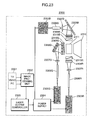
- FIG. 23 is an explanatory view schematically showing the structure of a projector (projection display) adopting a laser light source in accordance with still another embodiment of the present invention.
- FIG. 24A is an explanatory view schematically showing an example structure of a liquid crystal display adopting a laser light source of the present invention
- FIG. 24B is a cross-sectional view of the liquid crystal display of FIG. 24A ;
- FIG. 25 is an explanatory view schematically showing an example structure of a laser light source provided with fiber adopting the laser light source of the present invention
- FIG. 26A is a graph showing the relationship between a light intensity and a beam diameter directly before being connected to a transmission-use fiber when adopting a beam diameter change mechanism of FIG. 25 ;
- FIG. 26B is a graph showing the relationship between a light intensity and a transmission-use fiber NA when adopting a beam diameter change mechanism of FIG. 25 .
- a method of obtaining the temperature of the wavelength conversion element and setting the element temperature at a predetermined temperature value will be explained.
- a method of determining a timing of re-setting the temperature of the wavelength conversion element at an optimal temperature in consideration of changes in temperature of the wavelength conversion element as time passes and a method of making fine adjustments on the temperature of the wavelength conversion element.
- the method of switching a temperature at which a wavelength conversion element 209 is held according to a fundamental wave power level with which a harmonic wave of the output power level as set in an output setting device 201 can be obtained.
- a wavelength conversion laser light source 200 in accordance with the present embodiment includes a fundamental wave light source 231 , a first dichroic mirror 236 , a second dichroic mirror 237 , a collective lens 208 , a non-linear optical crystals (wavelength conversion element) 209 , a re-collimating lens 211 , a photoreceptor (photodiode) 212 , a beamsplitter 213 , etc.
- the fundamental wave light source 231 adopted is a fiber laser light source adopting a Yb doped fiber 233 . It is advantageous to adopt a fiber laser light source in that the oscillation wavelength and the spectrum width can be determined as desired. Therefore, when adopting such fiber laser light source, it is possible to significantly improve the conversion efficiency from a fundamental wave into a harmonic wave by reducing the spectrum width.
- the fundamental wave 235 generated by the fundamental wave light source (fiber laser light source) 231 is collected into the non-linear optical crystals (wavelength conversion element) 209 by the collective lens 208 .
- MgO:LiNbO 3 crystal element MgLN element
- MgLN element MgO:LiNbO 3 crystal element
- the wavelength conversion laser light source 200 in accordance with the present embodiment is provided with the temperature holder 216 under the lower surface of the wavelength conversion element (non-linear optical crystals) 209 .
- This temperature holder 216 serves to maintain the wavelength conversion element 209 at a predetermined holding temperature.
- adopted is a Peltier device.
- the second harmonic wave having wavelength converted by the wavelength conversion element 209 is formed into a parallel beam by the re-collimating lens 211 . After having formed into the parallel beam, the beam is separated by the beamsplitter 213 into a fundamental wave which has not been converted to the harmonic wave, and the harmonic wave as being converted.
- the laser output is controlled with current supplied to the pump light source of the fundamental wave light source 231 .
- such method of controlling the fundamental wave input may be adopted, wherein a part of the fundamental wave may be taken out directly before the fundamental wave is incident into the wavelength conversion element 209 , to monitor the incident light into the wavelength conversion element 209 .
- a beam splitter 213 and a photoreceptor (photodiode) 212 are provided before and after the wavelength conversion element 209 . However, it may be arranged so as to provide the beam splitter 213 and the photoreceptor 212 either before or after the wavelength conversion element 209 .
- FIG. 3 is a graph showing the relationship between the fundamental wave input and the second harmonic wave output, and the relationship between the fundamental wave input and a shift in temperature ⁇ t(° C.) from a phase matching temperature T(° C.) of the wavelength conversion element 209 with a power of the input fundamental wave of 500 mW when adopting the wavelength conversion laser light source 200 in accordance with the present embodiment.
- the phase matching temperature becomes lower.
- the phase matching temperature is reduced from the temperature initial value by 1.3 (° C.).
- FIG. 4 is a graph showing the relationship between the second harmonic wave output (W) and a shift in temperature ⁇ t(° C.) from a phase matching temperature T(° C.) of the wavelength conversion element 209 with a parameter of fundamental wave input of 500 mW.
- the peak value of the curve i.e., a shift in temperature ⁇ t from the phase matching temperature T(° C.) of the wavelength conversion element 209 is shifted to the lower temperature side as the output power level for the second harmonic wave (W) is increased as in case of the graph of FIG. 3 .
- FIG. 5 is a graph showing the relationship between the fundamental wave input and the second harmonic wave output with a parameter of a shift in temperature ⁇ t from a phase matching temperature T(° C.) of the wavelength conversion element 209 with a power of the input fundamental wave of 500 mW.
- T(° C.) phase matching temperature
- FIG. 5 shows that in some holding temperature range for the wavelength conversion element 209 , the output power of the harmonic wave is increased as the power of the fundamental wave increases. However, in other holding temperature ranges, the output power of the harmonic wave is decreased as the power of the fundamental wave increased from a certain point for the input power of the fundamental wave.
- an increase or a decrease in output power of the light source should correspond to increase or decrease in current applied.
- a decrease in output power of the second harmonic wave raises the problem not only in that an efficient conversion cannot be performed but also in that the output power for the second harmonic wave cannot be increased with an increase in input power of the fundamental wave under the auto power control, namely, the output power cannot be controlled.
- the output power for the harmonic wave may be adjusted as desired by adjusting temperature the wavelength conversion element 209 .
- the wavelength conversion element 209 absorbs in an excess amount of harmonic wave output at the moment the phase matching state is realized. Further, heat generated from the wavelength conversion element by absorbing the harmonic wave output, may result in the problem of damage in wavelength conversion crystals.
- the present and subsequent embodiments will discuss the method of preventing an occurrence of such event that the output power of the harmonic wave becomes out of control due to the properties of absorbing light of the wavelength conversion element 209 .
- the graph of FIG. 6 shows the relationship between a shift in temperature ⁇ t(° C.) from the phase matching temperature T(° C.) of the wavelength conversion element 209 with a power of the input fundamental wave of 500 mW and an output power of the second harmonic wave with a parameter of fundamental wave input.
- a peak search is carried out to obtain a temperature of the wavelength conversion element 209 at which the output power for the harmonic wave is maximized according to a difference in input power of the fundamental wave.
- the resulting optimal temperature of the wavelength conversion element 209 is stored in the EEPROM (ELECTRICALLY ERASABLE PROGRAMMABLE READ-ONLY MEMORY) 706 .
- the optimal temperature as stored in the EEPROM 706 is read to be switched from the currently set temperature of the wavelength conversion element 209 when next setting the output power for the output setting device 201 .
- the information indicative of that the output powers 1 W, 1.6 W and 2.2 W of the second harmonic wave correspond to input powers 4 W, 5.5 W and 7.0 W of the fundamental wave respectively, and the information indicative of that respective temperatures of the wavelength conversion element 209 corresponding to the output level (1 W, 1.6 W and 2.2 W) of the second harmonic wave are A ° C., B ° C. and C ° C. are recorded in the EEPROM 706 when shipping from the factories, in the form of input current to the fundamental wave light source 231 .
- the temperature of the wavelength conversion element 209 is set under the following conditions. x ⁇ 1:A ° C. 1 ⁇ X ⁇ 1.6:B ° C. 1.6 ⁇ X ⁇ 2.2:C ° C. 2.2 ⁇ X:temperature is not set and re-input is required.
- a caution signal is outputted to inform the user that the temperature is being adjusted.
- the wavelength conversion element 209 is reached to the holding temperature as set, it is set in a stand-by state to be ready for the output of a harmonic wave laser.
- a harmonic wave is outputted from the wavelength conversion laser light source 202 .
- a change in target temperature of the wavelength conversion element 209 may be required in response to a change in set output power of the harmonic wave by the output setting device 201 .
- the target temperature of the wavelength conversion element 209 is changed under the above conditions.
- the auto power control is performed by adjusting a current applied to the pump LD, to reduce functions in output power.
- a caution signal is outputted from the control unit 225 to inform the user that the target output power is being changed.
- FIG. 7 is a block diagram showing schematic structures of the control unit 255 and the temperature controller 711 of the wavelength conversion element 209 provided with the wavelength conversion laser light source in accordance with the present embodiment.
- the temperature controller 711 includes a power supply 708 , a thermistor 703 , an A/D converter 704 for converting a temperature signal from the thermistor 703 into a digital value, a register 705 storing a temp.
- EEPROM 706 for storing a table of temperatures of the wavelength conversion element 209 corresponding to respective output powers of the harmonic wave and current required, an MPU 707 to which the data indicative of a set value for the output power of the harmonic wave from the control unit 225 is transferred from the control unit 225 , and a switch 709 which controls the PWM (Pulse Width Modulation) with respect to the current wavefrom to be supplied to the temperature holder 216 from the power supply 708 .
- PWM Pulse Width Modulation
- the temperature holder 216 is controlled in the following manner. That is, the information indicative of the temperature of the wavelength conversion element 209 corresponding to the output level (output power level) of the harmonic wave as stored in the EEPROM 706 is obtained. Then, the MPU 707 compares and computes the temperature of the wavelength conversion element 209 as obtained with the temperature present value stored in the register 705 . As a result, the temperature holder 216 is controlled based on the current to be applied to the temperature holder 216 from the power supply 708 in view of the polarity and the waveform of the current under the PWM (Pulse Width Modulation) control by giving instructions to the switch 709 .
- PWM Pulse Width Modulation
- the wavelength conversion element 209 is placed on the temperature holder 216 , and the temperature of the wavelength conversion element 209 is monitored indirectly by monitoring the temperature of the temperature holder 216 .
- the temperature signal from the thermistor 703 is converted into a digital value by the A/D converter 704 to be stored in the register 705 .
- the temperature signal from the thermistor 703 is converted into a digital value by the A/D converter 704 to be stored in the register 705 .
- the EEPROM 706 stored beforehand together with input currents is a table for the temperatures of the wavelength conversion element, which respectively correspond to the output powers of the harmonic wave.
- the set value for the output power for the harmonic wave is transferred from the control unit 225 to the MPU 707 .
- the element temperature corresponding to the set value for the output power as transferred is obtained from the EEPROM 706 .
- the MPU 707 compares and computes the element temperature thus obtained with respect to the element temperature present value stored in the register 705 .
- the temperature holder 216 is controlled based on the current to be applied to the temperature holder 216 from the power supply 708 in view of the polarity and the waveform of the current under the PWM (Pulse Width Modulation) control by giving instructions to the switch 709 .
- PWM Pulse Width Modulation
- FIG. 8 is a flowchart showing processes of controlling a wavelength conversion element by a temperature controller in normal state in accordance with the present embodiment.
- FIG. 9 is a flowchart showing processes of controlling a wavelength conversion element by a temperature controller when executing the element temperature learning processes in accordance with the present embodiment.
- the temperature initial value T of the temperature holder 216 for the wavelength conversion element 209 is obtained (S 1 ). Then, the output power set value Psv as set in the output setting device 201 is obtained from the control unit 225 (S 2 ). Based on the set Psv, the Tsv is obtained from the EEPROM 706 (S 3 ), to be set as the target element temperature (S 4 ). Before starting the temperature control, the temperature present value Tpv of the wavelength conversion element 209 is obtained from the thermistor 703 (S 5 ). Then, the polarity of current to be applied to the temperature holder 216 (in the case of adopting the Peltier device as the temperature holder 216 ) and the waveform are subjected to control.
- a coefficient G is computed for use in controlling the current waveform based on the temperature initial value T, the temperature set value Tsv and the temperature present value Tpv (S 6 ).
- G ( Tpv ⁇ T )/( Tsv ⁇ T ) (1)
- the duty ratio is switched based on the coefficient G thus computed in S 6 to control the current waveform.
- the coefficient a in the inequality (2) is adopted for preventing the polarity of the current to be switched to the normal state frequently. It is preferable that the coefficient a falls in a range of from 1.1 to 1.2.
- the current may be cut to reduce the temperature of the wavelength conversion element 209 by natural cooling.
- the temperature learning processes refer to the processes of re-setting the target holding temperature of the wavelength conversion element to an optimal temperature for the desired output power of the harmonic wave, as such target holding temperature is subjected to change as time passes.
- the output power set value Psv for leaning is obtained from the EEPROM 706 (S 21 ).
- the temperature set value Tsv is determined based on the output power set value Psv for learning (S 22 ).
- a phase matching temperature of the wavelength conversion element 209 is searched based on peak hold by scanning temperatures. Therefore, the initial temperature set value is set to 0.5 (° C.) below Tsv (S 23 ).
- the harmonic wave is actually generated to obtain the harmonic wave output Ppv 1 , to be stored in the register 705 (S 24 ).
- the temperature set value Tsv is then increased by 0.05 (° C.) to be replaced with the currently set temperature (S 25 ).
- the harmonic wave output Ppv (n+1) of the nth loop is obtained to be temporarily stored in the register 705 (S 26 ).
- the harmonic wave output Ppv (n+1) is compared with the harmonic wave output Ppv n (S 27 ).
- the initial temperature set value is set to 0.5 (° C.) below Tsv.
- how many degrees to be decreased from the Tsv is to be determined based on the tolerance range for temperatures (temperature range at which the output level is 1 ⁇ 2) of the wavelength conversion element 209 , i.e., half width at half maximum, HWHM from the peak to the 1 ⁇ 2 of the output level.
- a drop in temperature be set to 0.5 to 1 times of the tolerance range for the temperature ⁇ t of the wavelength conversion element 209 .
- the harmonic wave output increases monotonically with respect to the fundamental wave input.
- the range for the harmonic wave above 1.0 W a problem arises in that the auto power control cannot be performed at the temperature of the wavelength conversion element set to the phase matching temperature if the temperature of the wavelength conversion element is subjected to change due to some disturbances as shown in the graph of FIG. 5 .
- the target temperature below the phase matching temperature by 0.3 (° C.) to 0.05 (° C.) for the following reason: That is, the temperature tuning curve is shifted to the lower temperature side with respect to the fundamental wave input ( FIG. 4 ). Namely, if the target temperature is set to the phase matching temperature, the output power for the harmonic wave cannot be increased with an increase in input power of the fundamental wave. It is therefore effective to shift beforehand the target temperature to the low temperature side.
- how many degrees to be decreased from the phase matching temperature should vary according to various factors such as the length of the wavelength conversion element 209 , the tolerance range for temperatures, focal conditions of the fundamental wave (beam waist diameter, focal position).
- the temperature set value can be shifted to a lower temperature side from the phase matching temperature, for example, by increasing the length of the wavelength conversion element 209 , increasing the beam diameter, or moving the focal position of the fundamental wave closer to the light incident surface of the element.
- a timing at which the element temperature leaning processes are to be executed may be set automatically, for example, by the following method. That is, directly before and after driving the device, the capacity left to the upper limit current to be applied to the pump LD is detected and recorded in the EEPROM 706 .
- the element temperature learning processes may be carried out when the following equation (4) is satisfied.
- I 1 ⁇ (1+ d/ 100) I lim (4)
- I 1 indicates the required LD current for obtaining the output P 1
- d (%) is a margin left to the limit value I lim to be applied to the pump LD and the auto power control.
- a program may be set to instruct a computer to automatically carry out the temperature learning processes when it is determined that the element temperature learning processes are to be carried out while informing the user of that the device is being in the element temperature learning processes.
- it may be arranged such that the user operates the device to execute the temperature learning processes in response to a caution to do so.
- the device cannot be used while the temperature learning processes are being executed. It is therefore desirable that the information indicative of being in the processes of learning temperature is displayed using the operation panel, and that the device is set in a locked state except for the case where the user needs to operate to shut down the device to execute an automatic emergency shutdown system.
- a peak search is to be executed for an optimal temperature of a wavelength conversion element 209 for output powers set to 10% to 20% above the output power that can be set in the output setting device 201 .
- explanations will be given through the case of using the results of search performed in the entire range for output powers.
- the required harmonic wave output value is set to 2.2 W, and the peak search is to be carried out for the output power of the harmonic wave of 2.6 W, which is approximately 1.2 times of the required output power (2.2 W).
- FIG. 10 is a graph showing the relationship between the fundamental wave input and the second harmonic wave output (w) with a parameter of a shift in temperature ⁇ t(° C.) from a phase matching temperature T(° C.) of a wavelength conversion element 209 with a power of the input fundamental wave of 500 mW.
- the output power of the harmonic wave can be increased monotonically with respect to the fundamental wave input in the output power of the harmonic wave range of 0 W to 2.6 W. Then, the harmonic wave output can be controlled with the auto power control based on the current to be applied to the pump LD.
- the output power of the harmonic wave for example, to 2.2 W
- the output power of the harmonic wave it is appropriate to set the output power of the harmonic wave to 2.2 W when actually driving the device including the control margin, i.e., the output power that can be set in the output setting device 201 in view of the fact that the output power of the harmonic wave will be saturated at above the output power of the harmonic wave of 2.6 W.
- FIG. 11 is a flowchart showing processes of controlling a wavelength conversion element when executing the element temperature learning processes.
- the initial temperature (Tsv 0 ) for learning is obtained from the EEPROM 706 (S 32 ).
- the scanning of temperatures is carried out with the temperature set value of the wavelength conversion element 209 , which is set to 0.5 (° C.) below Tsv 0 (S 33 ).
- the harmonic wave output Tsv 1 is actually generated, to be stored in the register 705 (S 34 ).
- the temperature set value Tsv is then increased by 0.05 (° C.) to be replaced with the currently set temperature (S 35 ).
- the harmonic wave output Ppv (n+1) of the nth loop is obtained to be temporarily registered in the register 705 (S 36 ).
- the harmonic wave output Ppv (n+1) is compared with the harmonic wave output Ppvn (S 37 ). If the following inequality (5) is satisfied (YES in S 37 ), the temperature set value Tsv is increased again by 0.05 (° C.) to be replaced with the currently set temperature repetitively. Ppv n ⁇ Ppv (n+1) (5).
- the temperature set value Tsv is then reduced by 0.05 (° C.) to be stored in the EEPROM 706 as an optimal temperature value (S 38 ), thereby terminating the foregoing element temperature learning processes.
- the target output power level of the harmonic wave is obtained after carrying out the re-scanning, it is determined if the margin left for the upper limit current is less than 5% (S 42 ). If it is determined that the margin left is less than 5%, an error flag is outputted (S 43 ).
- FIG. 12 is a graph showing differences in conversion efficiency between the case wherein temperature learning processes are executed with an optimal holding temperature set for each output power level (first embodiment) and the case wherein temperature learning processes are executed with an optimal holding temperature set for an upper limit output power level (present embodiment).
- the target output power level of the harmonic wave was not able to be obtained with the input power of the fundamental wave of less than 5 W.
- the harmonic wave of the output power of 1 W or higher is obtained with the input power of the fundamental wave of 5 W.
- the element temperature learning method in accordance with the present embodiment is disadvantageous in that the conversion efficiency is lowered as compared to the case of adopting the method of the first embodiment.
- the element temperature learning method is advantageous in that the time required for learning can be reduced as compared to the case of adopting the method of the first embodiment wherein the element temperature is obtained for each output power of the harmonic wave.
- the foregoing method of setting the element temperature in accordance with the present embodiment is also advantageous in the following point. That is, the output power of the second harmonic wave is saturated even when the input power of the fundamental wave is increased. It is therefore possible to prevent the wavelength conversion element from being damaged due to an increase in light absorption ratio in proportion to the power of the second harmonic wave generated by absorbing the second harmonic wave, two-photon absorption in particular.
- a peak search is to be executed for an optimal temperature of the wavelength conversion element 209 for output powers set to some hundreds mW which is lower than that of the second embodiment.
- the graph of FIG. 13 shows the relationship between the optimal temperature of the wavelength conversion element (shift in temperature from the phase matching temperature) and the second harmonic wave output generated at the optimal element temperature with respect to the fundamental wave input.
- the optimal element temperature (reference element temperature) is learned with a fundamental wave with an input power of 2 W is set as the reference fundamental wave.
- a shift in temperature from the reference element temperature corresponding to the fundamental wave different from the reference fundamental wave is recorded in the EEPROM 706 . In this way, it is possible to shift the element temperature by computing the necessary element temperature from the fundamental wave input required for obtaining the harmonic wave set in the output setting device 201 .
- FIG. 14 is a flowchart showing processes of controlling a wavelength conversion element by a temperature controller in accordance with the present invention in normal state.
- FIG. 15 is a flowchart showing processes of controlling a wavelength conversion element by a temperature controller when executing the element temperature learning processes in accordance with the present embodiment.
- an optimal element temperature T is obtained when outputting lower power harmonic wave from the EEPROM 706 (S 51 ). Then, the temperature of the harmonic wave conversion element 209 is adjusted to the element temperature T, and the device is set in a standby state (S 52 ).
- the output set value Psv is obtained from the EEPROM 706 (S 54 ).
- the input set value Isv and the ⁇ T required for the target output level are obtained from the EEPROM 706 (S 55 ).
- ⁇ T thus obtained in S 55 is subtracted from the optimal element temperature T for low power output (S 56 ), and the resulting temperature is set (S 57 ).
- the temperature learning processes of the present embodiment differ in that only ⁇ T is used for the information indicative of target temperature of the wavelength conversion element from other embodiments which use information indicative of temperatures corresponding to the output power levels of the harmonic wave.
- the temperature present value Tpv of the wavelength conversion element 209 is obtained from the thermistor 703 (S 58 ). Then, the processes for controlling current to be applied to the temperature holder 216 are started with regard to the waveform and the polarity (in the case of adopting Peltier device as the temperature holder 216 ) of the current to be applied to the temperature holder 216 in the same manner as the first embodiment explained with reference to the flowchart of FIG. 8 .
- a coefficient G for use in controlling the current waveform is computed from the following formula (6) based on the temperature initial value T, the set temperature value Tsv, and the temperature present value Tpv (S 59 ).
- G ( Tpv ⁇ T )/( Tsv ⁇ T ) (6).
- the current waveform is controlled by switching a duty ratio, based on the coefficient G computed in S 58 .
- the coefficient a in the inequality (7) is adopted for preventing the polarity of current to be switched to the normal state frequently. It is preferable that the coefficient a falls in a range of from 1.1 to 1.2.
- the current may be cut to reduce the temperature of the wavelength conversion element 209 by natural cooling.
- the temperature present value Tpv is obtained, and the processes for controlling current to be applied to the temperature holder 216 are started with regard to waveform and polarity (in the case of adopting Peltier device as the temperature holder 216 ) based on the temperature initial value T, the temperature set value Tsv, and the temperature present value Tpv.
- the temperature set value is not changed unless the output power set value changes via the control unit 225 from the output setting device 201 . Namely, when the auto power control is performed, it is known the fundamental wave input level is subjected to fluctuations. In the present embodiment, the temperature of the wavelength conversion temperature is not adjusted for such fluctuations.
- the output set value Psv for learning is obtained from the EEPROM 706 .
- the output set value Psv for learning is set to be low.
- the output level of the harmonic wave outputted from the wavelength conversion element 209 is set in a range of from 100 mW to 200 mW.
- the input current I p0 for learning is obtained from the EEPROM 706 (S 71 ).
- the initial temperature (Tsv 0 ) for learning is obtained from the EEPROM 706 (S 72 ).
- Tsv 0 the initial temperature
- the temperature set value is set to 0.5 (° C.) below Tsv (S 73 ).
- the harmonic wave with an output level of Ppv 1 is actually generated, to be stored in the register 705 (S 74 ).
- the temperature set value Tsv is then increased by 0.05 (° C.) to be replaced with the currently set temperature (S 75 ).
- the harmonic wave with an output level of Ppv (n+1) of the nth loop is obtained to be temporarily stored in the register 705 (S 76 ).
- the harmonic wave with an output level of Ppv (n+1) is then compared with the harmonic wave with an output level of Ppv n (S 77 ).
- the initial temperature set value is set to 0.5 (° C.) below Tsv.
- how many degrees to be decreased from the Tsv is to be determined based on the tolerance range for temperatures (temperature range at which the output level is 1 ⁇ 2) of the wavelength conversion element 209 , i.e., half width at half maximum, HWHM from the peak to the 1 ⁇ 2 of the output level.
- a drop in temperature be set to 0.5 to 1 times of the tolerance range for the temperature ⁇ t of the wavelength conversion element 209 .
- the foregoing present embodiment performs the same operation as those of the first and second embodiments except for that the input level for fundamental wave for learning is set for a small output level for the harmonic wave as compared to those in the first and second embodiments.
- the method of determining a re-setting timing for the holding temperature and the method of making fine adjustments on the temperature of the wavelength conversion element 209 will be explained in consideration of changes in desirable holding temperature of the wavelength conversion element 209 as time passes.
- the present embodiment adopts the following method. That is, the timing for executing the element temperature learning processes is determined based on how closer to the upper limit current value for the pump LD 232 , is the current value required to be applied to the pump LD 232 in order to obtain the harmonic wave of an output level as set in the output setting device 201 .
- the ratio of the current value I pv in the pump LD 232 to the current limit current value I lim to the pump LD 232 is monitored, to determine the re-setting timing for the temperature of the wavelength conversion element 209 as explained below.
- the process of computing the I pv /I lim is incorporated, so that the ratio of the current value Ipv that flows in the pump LD 232 to the upper limit current value for the pump LD 232 can be monitored through out the element learning processes.
- the ratio of the current value I pv to the current limit value I lim of the pump LD 232 satisfies the following inequality (9), it is determined that the ratio falls in a normal range to perform the normal state operation. 0 ⁇ I pv /I lim ⁇ 0.8 (9).
- the ratio of the current value I pv to the current limit value I lim of the pump LD 232 satisfies the following inequality (10), it is determined that the ratio falls in an abnormal range, and therefore determined that the element temperature learning processes are to be executed. 0.8 ⁇ I pv /I lim (10).
- an auto power control method may be adopted, wherein the current value required to be applied to the pump LD 232 to obtain the harmonic wave of the output level as set in the output setting device is recorded in the EEPROM 706 before or after driving.
- I 1 indicates a required LD current value for obtaining the output P 1
- d (%) indicates a margin required for the limit value I lim of the current to the pump LD 232 and the auto power control.
- a program may be set to instruct a computer to automatically carry out the temperature learning processes when determined based on the equation (11) that it is desirable to execute the element temperature learning processes while informing the user of that the device is being in the element temperature learning processes.
- it may be arranged such that the user operates the device to execute the temperature learning processes in response to a caution to do so.
- a harmonic wave output is generated using a rectangular modulation, and the modulation waveform of the driving current is compared with the waveform of the harmonic wave output, and the present temperature of the wavelength conversion element 209 is determined and is adjusted (fine adjustment) based on which part of the output waveform is lacked.
- a method of making fine adjustments on the temperature of the wavelength conversion element will be explained, wherein a harmonic wave output is generated using a rectangular modulation, and the waveform of the current to be inputted to the fundamental wave light source 231 is compared with the waveform of the harmonic wave output.
- FIGS. 16A to 16C show the relationship between the temperature of the wavelength conversion element 209 and the harmonic wave output pulse waveform.
- FIGS. 16A to 16C show the harmonic wave output waveform when applying the current pulse waveform with the pulse width of 20 msec and the duty of 33% as a modulation signal to the light source in the case of obtaining the harmonic wave of the output level of 2.2 W in response to the fundamental wave input of 6.5 W at a wave height value.
- FIG. 16A shows the case where the temperature of the wavelength conversion element 209 is 0.3 (° C.) below the phase matching temperature
- FIG. 16B shows the case where the temperature of the wavelength conversion element 209 is at the phase matching temperature;
- FIG. 16C shows the where the temperature of the wavelength conversion element 209 is 0.3 (° C.) above the phase matching temperature.
- the dotted line shown in FIG. 16A and FIG. 16C show the shape of the current signal waveform to be inputted to the fundamental wave light source.
- the wave height value as set can be obtained for the latter half of the output waveform as modulated, and the output waveform is lacked in a range of 20% to 50% at the beginning (at a rise) of the output waveform.
- the current pulse waveform is matched with the waveform of the harmonic wave actually outputted. As described, by comparing the current pulse waveform with the waveform of the harmonic wave output, it can be observed to which direction (lower temperature side or higher temperature side), the temperature of the wavelength conversion element 209 is shifted from the phase matching temperature.
- FIG. 17 is a flowchart showing processes of making fine adjustment in temperatures of the wavelength conversion element 209 based on pulse waveform in accordance with the present embodiment adopting the foregoing method.
- processes in the fine adjustment modes are executed in the state where the harmonic wave output is in the rectangular modulation.
- it may be arranged so as to set the light emission mode to the output modulation (rectangular modulation) when activating the fine adjustment mode.
- the waveform of the current to be inputted to the fundamental wave light source 231 is compared with the waveform of the harmonic wave (S 81 ).
- S 81 the waveform of the harmonic wave
- the temperature of the wavelength conversion element 209 is shifted to the lower temperature side from the phase matching state (S 82 ), i.e., if the harmonic wave waveform is lacked at the beginning (at a rise) as shown in FIG. 16A .
- the temperature of the wavelength conversion element 209 is increased until the current waveform is matched with the harmonic wave waveform (YES in S 82 ) by 0.05 (° C.) each time (S 83 ).
- the temperature of the wavelength conversion element 209 is decreased until the current waveform is matched with the harmonic wave waveform (YES in S 82 ) by 0.05 (° C.) each time (S 84 ).
- the temperature of the wavelength conversion element 209 is increased in a range of 0.05 (° C.) to 0.1 (° C.) each time.
- the lower limit of 0.05 (° C.) is set in consideration of the temperature detection precision, and the upper limit of 0.1 (° C.) is set in consideration of suppressing fluctuations in output level.
- the temperature of the wavelength conversion element 209 can be maintained in an appropriate temperature range by the foregoing processes, and the processes of making fine adjustments are terminated when the waveform of the current pulse is matched with the waveform of the harmonic wave.
- the current pulse waveform with the pulse width of 20 msec and the duty of 33% is inputted as a modulation signal to the fundamental wave light source 231 , and temperature of the wavelength conversion element 209 is adjusted to a phase matching temperature, based on the waveform of the harmonic wave as observed.
- the temperature of the wavelength conversion element 209 may be adjusted to the phase matching state based on the waveform of the harmonic wave output as observed when actually using in the output modulation state. This method is advantageous in that the temperature of the wavelength conversion element 209 can be adjusted while the device is being used.
- the modulation signal has a pulse width of not less than 100 ⁇ sec.
- a Q switch may be used for the fundamental wave light source 231 to oscillate a high peak pulse.
- the temperature of the wavelength conversion element 209 can be set by obtaining the pulse string of the harmonic wave output of not less than 100 ⁇ sec, and comparing the envelope with the current signal waveform.
- a wavelength conversion laser light source 200 in accordance with the present embodiment is arranged so as to change a beam diameter of the second harmonic wave itself according to the intensity of the second harmonic wave 220 by the wavelength conversion element (nonlinear optical crystals) 209 according to the intensity of the second harmonic wave 220 .
- the photoreceptor 212 of the wavelength conversion laser light source 200 restricts a value of the harmonic wave output based on changes in beam diameter.
- MgO:LiNbO 3 crystal element is adopted as the non-linear optical crystals, wherein the periodical polarization inversion structure is formed.
- the conversion efficiency from the fundamental wave to a green light (the second harmonic wave) can be improved significantly.
- the crystal element in the wavelength conversion optical system which satisfies the confocal condition it is possible to realize the function of varying the beam diameter according to the intensity of the second harmonic wave output.
- FIG. 18A An example of the optical system, wherein a beam shape varies according to an output level of a second harmonic wave, will be explained through an example shown in FIG. 18A .
- the graph of FIG. 18A shows the relationship between the second harmonic wave output level (wavelength of 532 nm) with respect to the fundamental wave (wavelength of 1064 nm).
- the beam diameter is stabilized in a range of the output of the second harmonic wave from 0 W to 1.6 W, and hardly varies ( FIG. 18B ).
- the beam diameter gradually becomes smaller, and at a point the output of the second harmonic wave exceeds 3 W, the beam becomes in a doughnut shape, and the harmonic wave output becomes unstable ( FIG. 18C ).
- the second harmonic wave output range (530 nm) in a range of from 2.3 W to 3.0 W
- the fundamental wave input is not larger than 6.5 w
- an abnormality in beam shape is not observed.
- the output of the second harmonic wave changes according to the wavelength. Specifically, it is confirmed that the longer is the wavelength, the larger is the output level.
- the second harmonic wave 220 having wavelength converted by the wavelength conversion element (non-linear optical crystal) 209 is formed into a parallel beam by the re-collimating lens 211 .
- the second harmonic wave 220 is separated by the beamsplitter 213 , and is partially received by the photoreceptor (photodiode) 212 .
- a main beam of the second harmonic wave 220 passes through the beamsplitter 213 , and is optically connected to a delivery optical fiber 206 from the optical fiber incident surface 206 a by the coupled lens 214 .
- the beam diameter of the second harmonic wave 220 changes, which in turn changes the NA at the focal position 701 of the beam as converged by the coupled lens 214 .
- the photoreceptor 212 is divided into the first region 1901 and the second region 1902 . In the present embodiment, it is arranged such that a normal beam 1903 is incident in the first region 1901 .
- the light beam is incident in the second region 1902 of the photoreceptor 212 .
- FIG. 20A is a block diagram schematically showing a structure of a control unit of a mechanism of detecting an abnormality in beam diameter in accordance with the present embodiment.
- FIG. 20B is a flowchart showing control processes by the control unit 225 for detecting an abnormality in beam diameter in accordance with the present embodiment.
- control unit 225 includes, an A/D converter 2001 , a D/A converter 2002 , an MPU 2003 , and a register 2004 .
- An amount of light received is obtained in the first region 1901 of the photoreceptor 212 , and is stored (S 91 ).
- An amount of light received is obtained also in the second region 1902 of the photoreceptor 212 , and is stored (S 92 ).
- These amounts of light received are converted into digital signals by the A/D converter 2001 , and are then stored in the register 2004 shown in FIG. 20A .
- the MPU 2003 computes a difference using respective amounts of light as stored (S 93 ).
- the information indicative of a low power mode is displayed in, for example, a consol of the device (S 96 ).
- the coefficient d adopted in the difference computation may be set to 0.5, for example.
- FIG. 21A through FIG. 21C are explanatory views, which depict examples of a photoreceptor of a mechanism of detecting an abnormality in beam diameter in accordance with the present embodiment.
- the difference computation is performed with a coefficient d of 0.5 in the present embodiment; however, the coefficient d can be set in a range of from 0 to 0.5 in consideration of a stray light generated in the optical arrangement, or the like.
- the present embodiment is not intended to be limited to those divided into two regions, and, for example, those divided into three regions (regions 2101 , 2102 and 2103 ) as shown in FIG. 21A , and those divided into four regions may be adopted.
- a photoreceptor 212 masked with a pinhole 2104 as shown in FIG. 21B , or the CCD (Charge Coupled Device) element 2105 may be used as shown in FIG. 21C .
- the photoreceptor 212 masked with the pinhole 2104 shown in FIG. 21B is most suited in terms of manufacturing costs; however, when adopting this photoreceptor 212 , it is required to determine if an abnormality in beam shape occurs by collating with the input value of the current applied to the pump LD 232 . In the case of adopting the CCD element 2105 shown in FIG. 21C , it is required to perform the image processing, the image processing, or the image process when overflowing charges are required.
- the divided photodiode shown in FIG. 19B or FIG. 21A is the most desirable for convenience in use.
- the method of shifting the focal position of the fundamental wave may be adopted, which offers the same effect.
- FIG. 22A is an explanatory view schematically showing the structure of the control unit 225 for detecting the abnormality in beam diameter in accordance with the present embodiment.
- FIG. 22B is a flowchart showing control processes by the control unit 225 for detecting an abnormality in beam diameter in accordance with the present embodiment.
- the second harmonic wave 220 having wavelength converted by the wavelength conversion element (non-linear optical crystal) 209 is formed into a parallel beam by the re-collimating lens 211 . After having formed into the parallel beam, the beam is separated by the beamsplitter 213 into the harmonic wave by the photoreceptor (photodiode) 212 and the other beam. On the other hand, a main beam of the second harmonic wave 220 passes through the beamsplitter 213 , and is outputted to the outside.
- the photoreceptor 212 For the detection of an abnormality in beam diameter of the second harmonic wave 220 , adopted is the photoreceptor 212 divided into the first region 1901 and the second region 1902 , to obtain respective light amounts received in the first region 1901 and the second region 1902 , and a difference computation of light amounts respectively received in these regions is performed.
- the collective lens 208 is shifted from the position indicated by 208 ( a ) to the position indicated by 208 ( b ) so as to shift the focal position 2201 of the fundamental wave 235 to the light incident side (to the side of the focal position 2202 ).
- the beam in a doughnut shape becomes no longer observed; however, the amount of the second harmonic wave 220 generated would be reduced.
- the current applied to the pump LD 232 is increased, to maintain the light amount so that the output level of the second harmonic wave can be maintained while eliminating the beam in doughnut shape.
- the respective amounts of light received in the first region 1901 and the second region 1902 of the photoreceptor 212 are converted into digital signals by the A/D converter 2001 , and are then stored in the register 2004 (S 111 and S 112 ).
- the MPU 2003 computes a difference using respective amounts of light as stored (S 113 ).
- the collective lens 208 is shifted by a predetermined distance (S 115 ) to shift the focal position of the fundamental wave 235 to the light incident side when the inequality (13) is satisfied (YES in S 114 ) to avoid an abnormality in beam shape.
- P 1901 indicates an amount of light received in the first region P 1901
- the second region P 1902 indicates an amount of light received in the second region 1902 .
- the doughnut beam is not observed (NO in S 119 )
- the amount of light of the second harmonic wave incident in the first region 1901 is checked (S 120 ). If the amount of light of the second harmonic wave is not sufficient (NO in S 120 ), the current applied to the pump LD 232 is increased by a predetermined amount (S 121 ). Then, the driving is continued while repeating the foregoing steps 116 to S 121 until the amount of light of the second harmonic wave reaches the set value (YES in S 120 ).
- the amount of light of the fundamental wave is increased by increasing the current applied to the pump LD 232 , and in the meantime, an amount of the second harmonic wave incident in the first region 1901 is checked. Then, the processes are carried out along the flowchart of FIG. 22B , to maintain the second harmonic wave at the set output level while eliminating the beam in an abnormality shape (doughnut shape).
- a green laser to be incident into the fiber, with the beam quality (M 2 value) of 1.3 is adopted; however, it is confirmed that the sufficient effect as achieved from the present invention can be achieved as long as the green laser with the beam quality (M 2 value) of not higher than 2 is adopted.
- the non-linear optical crystals crystals which absorb light (two-photon absorption, for example) by a harmonic wave output, i.e., the wavelength of the harmonic wave generated, it is required to be less than 2 times of a wavelength of an absorption edge of nonlinear optical crystals of the wavelength conversion element.
- Examples of the nonlinear optical crystals of the wavelength conversion element satisfying the above condition includes: lithium niobate (including those having magnesium oxide added), lithium tantalite (including those having magnesium oxide added), KTiOPO 4 (KTP:Potassium Titanyl Phosphate), and the wavelength conversion element generates a green light having a wavelength in a range of from 520 nm to 560 nm from Nd:YAG laser or Yb fiber using these crystals.
- the wavelength conversion element having the light absorbing properties induced by the harmonic wave is used, and the temperature of the wavelength conversion element is set to a temperature at which the harmonic wave output level of 120% of that actually used can be obtained.
- searching the phase matching temperature i.e., an optimal temperature at which the wavelength conversion efficiency can be maximized, even if the fundamental wave input level becomes too high, the output of the second harmonic wave would be saturated.
- FIG. 23 , FIGS. 24A and 24B show an example structure of a two-dimensional image display apparatus adopting the fiber laser light source in accordance with the present embodiment.
- FIG. 23 schematically shows the structure of an optical engine of a projector system adopting a laser light source in accordance with the present embodiment.
- the two-dimensional image display device 2300 in accordance with the present embodiment has an optical engine for a projector using 3 LCD panels.
- the two-dimensional image display device 2300 includes an image processing section 2302 , a laser output controller (controller) 2303 , an LD power supply 2304 , red, green and blue laser light sources 2305 R, 2305 G, and 2305 B, beam shape rod lens 2306 R, 2306 G, and 2306 B, relay lens 2307 R, 2307 G and 2307 B, reflecting mirrors 2308 G and 2308 B, two-dimensional modulation elements 2309 R, 2309 G and 2309 B for displaying an image; polarizers 2310 R, 2310 G and 2310 B, a combine prism 2311 , and a projection lens 2312 .
- the green laser light source 2305 G is controlled by the controller 2303 and the LD power supply 2304 which control an output from the green light source.
- a laser beam emitted from each of the red, green and blue laser light sources 2305 R, 2305 G, and 2305 B are formed in a rectangular shape by the beam shape rod lens 2306 R, 2306 G, and 2306 B, and with which, the two-dimensional modulation element in each color is illuminated by the relay lens 2307 R, 1307 G, and 2307 B. Further, two-dimensionally modulated images in respective colors are combined by the combine prism 2311 , and the resulting image is projected onto the screen by the projection lens 2312 , thereby displaying an image.
- the green laser light source 2305 G is arranged such that a laser resonator is housed in the fiber. With this structure, it is possible to suppress a reduction in output level and fluctuations in output power as time passes due to an increase in loss in the resonator by dust particles from the outside or a misalignment of the reflective surface.
- a light amount control signal is generated for changing the output level of the laser beam according to the luminance information of the input image signal 2301 , and transmits the light amount control signal to the laser output controller 2303 .
- a contrast can be improved by controlling the light amount according to the luminance information.
- control method PWM control
- an average light amount is changed by pulse driving the laser beam to change the duty ratio (ON time)/(ON time+OFF time) for the ON time of the laser.
- the green light source adopted in this projection system may be arranged so as to emit a Green laser beam having a wavelength in a range of from 510 nm to 550 nm.
- the two-dimensional image display device of the present invention includes a screen, a plurality of laser light sources, a scanning section for scanning the laser light sources, wherein the laser light sources include at least laser sources which emit a red color laser beam, a green color laser beam, and a blue color laser beam; and at least the green color light source is provided with the wavelength conversion element having any of the foregoing structures.
- those of a rear projection display type ( FIG. 23 ), or of a front projection type may be adopted.
- a two-dimensional modulation element of the transmission type liquid crystal or the reflective type liquid crystal, a galvanometer mirror, a DMD or other Micro Electro Mechanical System (MEMS) may be used.
- the light modulation element which is less likely to be affected by polarization components with respect to the light modulation characteristics, such as the reflection-type special modulation element, the MEMS, the galvanometer mirror like the case of the present embodiment, it is not required to adopt a polarization-maintaining optical fiber such as a PANDA (polarization maintaining and absorption reducing) fiber for transmitting the harmonic wave with the optical fiber.
- a polarization-maintaining optical fiber such as a PANDA (polarization maintaining and absorption reducing) fiber for transmitting the harmonic wave with the optical fiber.
- PANDA polarization maintaining and absorption reducing
- FIG. 24 shows one example structure of a display adopting the laser light source.
- a liquid crystal display 2400 includes, for example, a laser light source 2402 , a control unit 2403 , a light guide member 2404 for converting the laser light source from a point light source to a linear light source, a light guide plate 2408 for converting the linear light source into a planar light source to be projected onto the entire liquid crystal panel, a polarization plate/diffusion member 2409 for aligning the polarization direction or removing the non-uniform illumination, and a liquid crystal panel 2410 , etc.
- the light source of the present invention may be used as a backlight source for the liquid crystal display.
- the laser device of the present invention may be used as a laser light source 2500 for surgical operations, which is made up of, for example, a laser light source, a control unit for controlling the output from the laser light source, an output setting device 2502 for setting an output level, an output connector 2503 for outputting a laser from a laser light source, a delivery fiber 205 for guiding the laser beam to a desired area to be irradiated with, and a hand peace 2505 , etc.
- a laser light source 2500 for surgical operations which is made up of, for example, a laser light source, a control unit for controlling the output from the laser light source, an output setting device 2502 for setting an output level, an output connector 2503 for outputting a laser from a laser light source, a delivery fiber 205 for guiding the laser beam to a desired area to be irradiated with, and a hand peace 2505 , etc.
- the NA is set to be large (NA: 0.12 in the case of the present embodiment).
- the NA is set to be small (NA: 0.09 in the case of the present embodiment).
- FIG. 26A is a graph showing the relationship between the light intensity and the beam diameter directly before being connected to a transmission-use fiber of the laser light source with fiber as shown in FIG. 25 .
- FIG. 26B is a graph showing the relationship between a light intensity and a transmission-use fiber NA of a laser beam to be incident into the delivery fiber 2504 .
- the NA to the delivery fiber 2504 becomes smaller as the beam diameter becomes smaller according to the output level.
- the auto power control APC cannot be performed as the output level is not raised in response to an increase in input power of the fundamental wave, or it becomes not possible to adjust changes in phase matching temperature of the wavelength conversion element as time passes.
- APC cannot be performed as the output level is not raised in response to an increase in input power of the fundamental wave, or it becomes not possible to adjust changes in phase matching temperature of the wavelength conversion element as time passes.
- a wavelength conversion laser light source includes: a fundamental wave laser light source; a wavelength conversion element for converting a fundamental wave emitted from the fundamental wave laser light source into a harmonic wave, the wavelength conversion element being made of a material whose light absorption properties change according to an output level of a harmonic wave; an output setting section for setting a harmonic wave output power level; and an element temperature switching section that switches a temperature of the wavelength conversion element according to a harmonic wave output level as set in the output setting device, wherein the element temperature switch section includes an element temperature holding section which holds the wavelength conversion element at the temperature as switched by the element temperature switching section.
- the phase matching temperature of the wavelength conversion element changes according to an output level of the harmonic wave.
- the element temperature switching section switches the element temperature of the wavelength conversion element according to the output level of the harmonic wave, and the element temperature holding section holds the wavelength conversion element at the element temperature as switched.
- the wavelength conversion element can be maintained at a desirable temperature corresponding to the output level of the harmonic wave, thereby realizing a high wavelength conversion efficiently.
- the element temperature holding section includes a memory for storing therein element temperatures to be held by the element temperature holding section.
- the element temperature holding section includes a temperature adjusting member capable of adjusting the temperature of the wavelength conversion element by heating or cooling the wavelength conversion element, an element temperature detector which detects the temperature of the wavelength conversion element, and a temperature controller which controls the temperature of the wavelength conversion element by controlling the temperature adjusting member, wherein the temperature controller controls the temperature adjusting member, to set a present temperature of the element temperature detector to the temperature as switched by the element section.
- the wavelength conversion element can be maintained at a desirable temperature according to the output level of the harmonic wave.
- the memory stores a driving current for the harmonic wave laser light source corresponding to a harmonic wave output power level.
- the harmonic wave of the desired output level can be obtained with ease based on the driving current for the fundamental wave laser light source stored in the memory.
- an element temperature learning section be further provided for learning a temperature of the wavelength conversion element as stored in the memory, to rewrite the currently stored temperature into a temperature as learned, wherein the element temperature learning section searches for an optimal element temperature at which a harmonic wave of the highest power can be outputted, with a start temperature for the search of a predetermined temperature ⁇ t(° C.) below the temperature of the wavelength conversion element as stored in the memory, and the element temperature learning section carries out the search by increasing the temperature from the start temperature, and stores in the memory the optimal temperature as searched.
- the element temperature learning section carries out the learning by a peak search for a maximum harmonic wave output value while changing the temperature of the wavelength conversion element.
- the element temperature learning section determines a temperature, at which a harmonic wave of the highest power can be outputted, as an optimal temperature corresponding to the harmonic wave output value.
- an element temperature learning section be provided for learning a temperature of the wavelength conversion element as stored in the memory, to rewrite the currently stored temperature into a temperature as learned, wherein the element temperature learning section searches for an optimal element temperature at which a harmonic wave of the highest power can be outputted, with a start temperature for the search of a predetermined temperature ⁇ t(° C.) below the temperature of the wavelength conversion element as stored in the memory, and the element temperature learning section carries out the search by increasing the temperature from the start temperature, and stores in the memory a temperature lower than the optimal temperature as searched.
- the lower temperature than that obtained by the learning processes is stored in the memory to be replaced with the currently stored temperature. It is therefore possible to prevent such problem that the output level of the harmonic wave cannot be increased with an increase in the input level of the fundamental wave. This can be seen from the tuning curve in the graph of FIG. 4 , which is shifted to the lower temperature side with respect to the fundamental wave input.
- the predetermined temperature ⁇ t(° C.) is in a range of 0.5 to 1 times of a tolerance range for a temperature ⁇ T(° C.) of the wavelength conversion element.
- I 1 indicates a driving current value of the fundamental wave laser light source required for obtaining a harmonic power of an output power value set in the output setting device
- I lim indicates a driving current limit value for the fundamental wave laser light source
- d (%) indicates a coefficient
- the memory stores a reference element temperature when a reference fundamental wave emitted from the fundamental wave laser light source is injected, and an amount of shift in temperature from the reference element temperature corresponding to the fundamental wave that is different from the reference fundamental wave, and the element temperature switch section switches a temperature of the wavelength conversion element to a temperature as computed based on a shift in temperature corresponding to the required fundamental wave for obtaining the harmonic wave of the output level set in the output setting section.
- an element temperature fine adjustment section be further provided that makes a fine adjustment on the temperature of the wavelength conversion element in a state where a rectangular pulse beam is outputted from the wavelength laser light source, wherein the element temperature fine adjustment section adjusts the element temperature so as to match a waveform of a current pulse for use in driving the fundamental wave light source with a waveform of the harmonic wave output as a result of comparison between these waveforms.
- a rectangular pulse is outputted from the wavelength conversion laser light source.
- the output waveform is lacked at the beginning (at a rise) of the output waveform of the harmonic wave.
- the output waveform is lacked at the end (at a fall) of the output waveform of the harmonic wave.
- the current pulse waveform is matched with the waveform of the harmonic wave actually outputted.
- the waveform of the current pulse with the waveform of the harmonic wave output by the element temperature fine adjustment section, it can be observed to which direction (lower temperature side or higher temperature side), the temperature of the wavelength conversion element is shifted from the phase matching temperature. Therefore, by carrying out a fine adjustment on the element temperature by the element temperature fine adjustment section so that the current pulse waveform is matched with the output waveform of the harmonic wave, it is possible to appropriately set the temperature of the wavelength conversion element to the phase matching temperature.
- the harmonic wave resulting from the wavelength conversion by the wavelength conversion element has a wavelength which is less than 2 times of a wavelength of an absorption edge of nonlinear optical crystals of the wavelength conversion element.
- the foregoing conditions are appropriate conditions for the wavelength conversion element made of a material whose light absorption properties vary according to the output level of the harmonic wave.
- the nonlinear optical crystals of the wavelength conversion element is LN:lithium niobate (including those having magnesium oxide added), lithium tantalate (including those having magnesium oxide added), KTiOPO 4 (KTP:Potassium Titanyl Phosphate), and the wavelength conversion element emits a green light having a wavelength in a range of from 520 nm to 560 nm as a result from the wavelength conversion.
- the wavelength conversion element has a beam diameter variable structure for varying a beam diameter of a harmonic wave outputted from the wavelength conversion element, the wavelength conversion laser light source further including a beam shape abnormality detection mechanism for detecting an abnormality in beam shape of the harmonic wave outputted from the wavelength conversion element.
- the wavelength conversion element has a beam diameter variable structure for varying a beam diameter of a harmonic wave, it is possible to detect an abnormality in the beam shape of the harmonic wave by the beam shape abnormality detection mechanism.
- the beam shape abnormality detection mechanism includes a photoreceptor which monitors an intensity of the harmonic wave outputted from the wavelength conversion element; and the photoreceptor includes a beam diameter detection mechanism for detecting an abnormality in beam diameter of the harmonic wave outputted from the wavelength conversion element.
- the wavelength conversion element having the beam diameter variable structure is MgO:LiNbO 3 having a periodical polarization inversion structure; and the harmonic wave has an output power of not higher than 3 W.
- the beam becomes in a doughnut shape, and the harmonic wave output becomes unstable at a point the output of the second harmonic wave exceeding 3 W.
- an abnormality in beam shape does not occur.
- the wavelength conversion element having the beam diameter variable structure is a MgO:LiTaO 3 crystal element having a periodical polarization inversion structure; and the harmonic wave has an output power of less than 6.5 W.
- the MgO:LiTaO 3 in the output range of not larger than 6.5 W of the harmonic wave, an abnormality in beam shape does not occur.
- the beam diameter detection mechanism includes a photodiode divided into segments.
- the photodiode divided into segments it is possible to detect an abnormality in beam shape (doughnut shape) of the harmonic wave output.
- the beam diameter detection mechanism is divided into two segments A and B; and the beam shape abnormality detection mechanism determines that an abnormality occurs in beam diameter of harmonic wave when satisfying the condition of: d ⁇ LA ⁇ LB (0 ⁇ d ⁇ 0.5),
- a segment A is a segment to be irradiated with the harmonic wave in a normal state
- a segment B is a segment to be irradiated with the harmonic wave in an abnormal state
- LA is an amount of the harmonic wave irradiated in the segment A
- LB is an amount of the harmonic wave irradiated in the segment B.
- the amount of harmonic wave received by the segment B would increase and the above condition is satisfied. It is therefore possible to accurately detect an occurrence of an abnormality in beam shape (beam diameter).
- a wavelength conversion laser light source includes: a fundamental wave laser light source; a wavelength conversion element for converting a fundamental wave emitted from the fundamental wave laser light source into a harmonic wave, the wavelength conversion element being made of a material whose light absorption properties are subjected to change according to an output level of a harmonic wave; an output setting section for setting a harmonic wave output power level; and an element temperature holding section which holds the wavelength conversion element at an optimal temperature set for a harmonic wave output power level corresponding to 110% to 120% of an upper limit of the output power level that can be set in the output setting device.
- the element temperature holding section includes a memory for storing therein element temperatures to be held by the element temperature holding section.
- the an element temperature learning section be provided for learning a temperature of the wavelength conversion element as stored in the memory, to rewrite the currently stored temperature into a temperature as learned; and the element temperature learning section which searches for an optimal element temperature at which a harmonic wave of the highest power can be outputted, with a start temperature for the search, a predetermined temperature ⁇ t(° C.) below the temperature of the wavelength conversion element as stored in the memory, wherein the element temperature learning section carries out the search by increasing the temperature from the start temperature, and stores in the memory the optimal temperature as searched.
- the element temperature learning section carries out the learning by a peak search for a maximum harmonic wave output value while changing the temperature of the wavelength conversion element.
- the element temperature learning section determines a temperature, at which a harmonic wave of the highest power can be outputted, as an optimal temperature corresponding to the harmonic wave output value.
- a two-dimensional image display device in accordance with still another aspect of the present invention includes: a wavelength conversion laser light source of any of the foregoing structure, a two-dimensional modulation element that two-dimensionally modulates an output beam from the wavelength conversion laser light source; and a projection lens that projects the output beam from the two-dimensional modulation element.
- the two-dimensional image display device adopting the wavelength conversion laser light source which permits a wavelength conversion with high efficiency even when a phase matching temperature of the wavelength conversion element changes according to the output level of the harmonic wave.
- a two-dimensional image display device in accordance with still another aspect of the preset invention includes: the light source unit including the wavelength conversion laser light source having any of the foregoing structures; and a liquid crystal panel which emits the output beam from the light source unit.
- the two-dimensional image display device adopting the wavelength conversion laser light source which permits a wavelength conversion with high efficiency even when a phase matching temperature of the wavelength conversion element changes according to the output level of the harmonic wave.
- a laser light source device in accordance with still another aspect of the preset invention includes: the wavelength conversion laser light source having any of the foregoing structure; and a fiber for guiding the harmonic wave outputted from the wavelength conversion laser light source to an irradiation area.
- the laser light source device which permits a wavelength conversion with high efficiency even when a phase matching temperature of the wavelength conversion element changes according to the output level of the harmonic wave.
- a temperature setting method of a wavelength conversion element in accordance with still another aspect of the present invention which is made of a material whose light absorption properties are subjected to change according to an output power of a harmonic wave resulting from converting the wavelength of a fundamental wave includes the steps of: setting a harmonic wave output level; and switching a temperature of the wavelength conversion element according to an output level of the harmonic wave.
- a temperature setting method of a wavelength conversion element in accordance with still another aspect of the present invention which is made of a material whose light absorption properties are subjected to change according to an output power of a harmonic wave resulting from converting the wavelength of a fundamental wave, includes the steps of: setting a harmonic wave output level; and setting an optimal temperature of the wavelength conversion element to a temperature at which a harmonic wave of an output level of 110% to 120% of an upper limit of the output level that can be set in the output setting device.
Abstract
Description
x<1:A ° C.
1≦X<1.6:B ° C.
1.6≦X<2.2:C ° C.
2.2≦X:temperature is not set and re-input is required.
G=(Tpv−T)/(Tsv−T) (1)
Tpv>a×Tsv (2)
Ppv n >Ppv (n+1) (3)
I 1×(1+d/100)=I lim (4)
Ppv n <Ppv (n+1) (5).
G=(Tpv−T)/(Tsv−T) (6).
Tpv>a×Tsv (7).
Ppv n >Ppv (n+1) (8).
0<I pv /I lim<0.8 (9).
0.8≦I pv /I lim (10).
I 1×(1+d/100)=I lim (11)
d×P1901<P1902 (12)
d×P1901<P1902 (13)
I 1×(1+d/100)=I lim
d×LA<LB(0<d<0.5),
Claims (9)
I 1×(1+d/100)=I lim
Priority Applications (1)
| Application Number | Priority Date | Filing Date | Title |
|---|---|---|---|
| US13/243,431 US8411714B2 (en) | 2007-12-07 | 2011-09-23 | Wavelength conversion laser light source, laser light source device and two-dimensional image display device adopting the same, and method of setting temperature of wavelength conversion element |
Applications Claiming Priority (4)
| Application Number | Priority Date | Filing Date | Title |
|---|---|---|---|
| JP2007-316895 | 2007-12-07 | ||
| JP2007316895 | 2007-12-07 | ||
| JP2008-060653 | 2008-03-11 | ||
| JP2008060653 | 2008-03-11 |
Related Child Applications (1)
| Application Number | Title | Priority Date | Filing Date |
|---|---|---|---|
| US13/243,431 Division US8411714B2 (en) | 2007-12-07 | 2011-09-23 | Wavelength conversion laser light source, laser light source device and two-dimensional image display device adopting the same, and method of setting temperature of wavelength conversion element |
Publications (2)
| Publication Number | Publication Date |
|---|---|
| US20090147811A1 US20090147811A1 (en) | 2009-06-11 |
| US8050302B2 true US8050302B2 (en) | 2011-11-01 |
Family
ID=40721622
Family Applications (2)
| Application Number | Title | Priority Date | Filing Date |
|---|---|---|---|
| US12/328,131 Expired - Fee Related US8050302B2 (en) | 2007-12-07 | 2008-12-04 | Wavelength conversion laser light source, laser light source device and two-dimensional image display device adopting the same, and method of setting temperature of wavelength conversion element |
| US13/243,431 Expired - Fee Related US8411714B2 (en) | 2007-12-07 | 2011-09-23 | Wavelength conversion laser light source, laser light source device and two-dimensional image display device adopting the same, and method of setting temperature of wavelength conversion element |
Family Applications After (1)
| Application Number | Title | Priority Date | Filing Date |
|---|---|---|---|
| US13/243,431 Expired - Fee Related US8411714B2 (en) | 2007-12-07 | 2011-09-23 | Wavelength conversion laser light source, laser light source device and two-dimensional image display device adopting the same, and method of setting temperature of wavelength conversion element |
Country Status (2)
| Country | Link |
|---|---|
| US (2) | US8050302B2 (en) |
| JP (1) | JP5352212B2 (en) |
Cited By (2)
| Publication number | Priority date | Publication date | Assignee | Title |
|---|---|---|---|---|
| US20110194173A1 (en) * | 2006-07-11 | 2011-08-11 | Thales | Method and device for spectral control in frequency conversion laser amplifiers |
| US20130022061A1 (en) * | 2010-03-31 | 2013-01-24 | Fujikura Ltd. | Fiber laser device |
Families Citing this family (12)
| Publication number | Priority date | Publication date | Assignee | Title |
|---|---|---|---|---|
| US8050302B2 (en) * | 2007-12-07 | 2011-11-01 | Panasonic Corporation | Wavelength conversion laser light source, laser light source device and two-dimensional image display device adopting the same, and method of setting temperature of wavelength conversion element |
| US8572426B2 (en) | 2010-05-27 | 2013-10-29 | National Semiconductor Corporation | Hardware performance monitor (HPM) with extended resolution for adaptive voltage scaling (AVS) systems |
| JP2012037813A (en) * | 2010-08-10 | 2012-02-23 | Nikon Corp | Ultraviolet laser device |
| JP2012203147A (en) * | 2011-03-24 | 2012-10-22 | Nikon Corp | Ultraviolet laser device |
| JP5754456B2 (en) * | 2013-03-21 | 2015-07-29 | ウシオ電機株式会社 | Laser light source device |
| CN104061446B (en) * | 2013-03-21 | 2018-04-03 | 优志旺电机株式会社 | Laser light-source device |
| JP5754455B2 (en) * | 2013-03-21 | 2015-07-29 | ウシオ電機株式会社 | Laser light source device |
| KR20160075085A (en) * | 2014-12-19 | 2016-06-29 | 삼성전기주식회사 | Lens assembly and camera module including the smae |
| JP6306659B1 (en) * | 2016-10-19 | 2018-04-04 | ファナック株式会社 | Beam distributor |
| JP7087928B2 (en) * | 2018-11-06 | 2022-06-21 | 日本電信電話株式会社 | Wavelength converter |
| CN112038873B (en) * | 2020-08-20 | 2021-12-03 | 华中科技大学 | Terahertz arbitrary waveform generation method and system |
| CN113218637B (en) * | 2021-06-08 | 2022-02-25 | 中国工程物理研究院激光聚变研究中心 | Method for acquiring harmonic conversion efficiency curve of full laser power section |
Citations (10)
| Publication number | Priority date | Publication date | Assignee | Title |
|---|---|---|---|---|
| JP2000305120A (en) | 1999-04-26 | 2000-11-02 | Nikon Corp | Resonator and microscope having resonator |
| JP2004157217A (en) | 2002-11-05 | 2004-06-03 | Fuji Photo Film Co Ltd | Wavelength converting laser beam source |
| US20060039423A1 (en) * | 2004-08-20 | 2006-02-23 | Nikon Corporation | Light source unit and light irradiation unit |
| US20070025401A1 (en) * | 2005-07-29 | 2007-02-01 | Nidek Co., Ltd. | Medical laser apparatus |
| US20080013574A1 (en) * | 2006-06-22 | 2008-01-17 | Hiroyuki Furuya | Laser light source device and image display device |
| US20090154509A1 (en) * | 2007-12-14 | 2009-06-18 | Keyence Corporation | Laser Processing Apparatus, Method For Making Settings For The Laser Processing Apparatus, Program For Making Settings For The Laser Processing Apparatus, and Computer-Readable Recording Medium |
| US20090323172A1 (en) * | 2008-06-30 | 2009-12-31 | Hiroyuki Furuya | Optical apparatus, and wavelength conversion laser light source, image display apparatus, and laser light source device adopting such optical apparatus |
| US20100008388A1 (en) * | 2006-10-24 | 2010-01-14 | Panasonic Corporation | Internal resonator type shg light source |
| US20100110533A1 (en) * | 2007-12-26 | 2010-05-06 | Panasonic Corporation | Laser light source, and image display apparatus and processing apparatus using the same |
| US20100208758A1 (en) * | 2007-01-09 | 2010-08-19 | Seiko Epson Corporation | Light source device, projector device, monitor device, and lighting device |
Family Cites Families (18)
| Publication number | Priority date | Publication date | Assignee | Title |
|---|---|---|---|---|
| JPH01128484A (en) * | 1987-11-12 | 1989-05-22 | Asukaru:Kk | High-efficiency second harmonic generating laser oscillator |
| JP2629621B2 (en) * | 1993-11-11 | 1997-07-09 | 日本電気株式会社 | UV laser equipment |
| KR100272196B1 (en) * | 1996-06-05 | 2000-12-01 | 나까니시 히로유끼 | Laser light generating apparatus |
| JP2001168439A (en) * | 1999-12-09 | 2001-06-22 | Fuji Photo Film Co Ltd | Light-emitting device |
| US6845113B2 (en) * | 2000-10-31 | 2005-01-18 | Matsushita Electric Industrial Co., Ltd. | Coherent light source and recording/reproducing apparatus using the same |
| WO2002091533A1 (en) * | 2001-05-07 | 2002-11-14 | Mitsubishi Denki Kabushiki Kaisha | Laser device, method of exciting the same, and laser processing machine |
| US7016389B2 (en) * | 2003-01-24 | 2006-03-21 | Spectra Physics, Inc. | Diode pumped laser with intracavity harmonics |
| JP2004281598A (en) * | 2003-03-14 | 2004-10-07 | Nidek Co Ltd | Laser device |
| KR101100010B1 (en) * | 2003-10-24 | 2011-12-28 | 파나소닉 주식회사 | 2-dimension light-receiving array and holographic optical information reproducing apparatus using it and holographic optical information recording apparatus |
| CN100424946C (en) * | 2004-02-27 | 2008-10-08 | 松下电器产业株式会社 | Coherent light source and control method thereof, and display unit and laser display using them |
| JP4860605B2 (en) * | 2005-03-25 | 2012-01-25 | パナソニック株式会社 | Wavelength conversion element |
| JP4914083B2 (en) * | 2005-06-30 | 2012-04-11 | キヤノン株式会社 | Optical wavelength conversion device, optical wavelength conversion method, and image forming apparatus using the same |
| US8018646B2 (en) * | 2005-07-28 | 2011-09-13 | Panasonic Corporation | Wavelength conversion element, laser light source, two-dimensional image display and laser processing system |
| US7692848B2 (en) * | 2005-10-12 | 2010-04-06 | Panasonic Corporation | Wavelength conversion module, laser light source device, two-dimensional image display device, backlight light source, liquid crystal display device and laser processing device |
| JP5191692B2 (en) * | 2006-06-22 | 2013-05-08 | パナソニック株式会社 | Laser light source device and image display device |
| US7576908B2 (en) * | 2006-07-06 | 2009-08-18 | Panasonic Corporation | Fiber device, wavelength converter and image forming apparatus |
| WO2008044673A1 (en) * | 2006-10-10 | 2008-04-17 | Panasonic Corporation | Wavelength converting device and image display device |
| US8050302B2 (en) * | 2007-12-07 | 2011-11-01 | Panasonic Corporation | Wavelength conversion laser light source, laser light source device and two-dimensional image display device adopting the same, and method of setting temperature of wavelength conversion element |
-
2008
- 2008-12-04 US US12/328,131 patent/US8050302B2/en not_active Expired - Fee Related
- 2008-12-05 JP JP2008311393A patent/JP5352212B2/en not_active Expired - Fee Related
-
2011
- 2011-09-23 US US13/243,431 patent/US8411714B2/en not_active Expired - Fee Related
Patent Citations (12)
| Publication number | Priority date | Publication date | Assignee | Title |
|---|---|---|---|---|
| JP2000305120A (en) | 1999-04-26 | 2000-11-02 | Nikon Corp | Resonator and microscope having resonator |
| JP2004157217A (en) | 2002-11-05 | 2004-06-03 | Fuji Photo Film Co Ltd | Wavelength converting laser beam source |
| US20060039423A1 (en) * | 2004-08-20 | 2006-02-23 | Nikon Corporation | Light source unit and light irradiation unit |
| US20070025401A1 (en) * | 2005-07-29 | 2007-02-01 | Nidek Co., Ltd. | Medical laser apparatus |
| US20080013574A1 (en) * | 2006-06-22 | 2008-01-17 | Hiroyuki Furuya | Laser light source device and image display device |
| US7733927B2 (en) * | 2006-06-22 | 2010-06-08 | Panasonic Corporation | Laser light source device and image display device |
| US20100008388A1 (en) * | 2006-10-24 | 2010-01-14 | Panasonic Corporation | Internal resonator type shg light source |
| US20100208758A1 (en) * | 2007-01-09 | 2010-08-19 | Seiko Epson Corporation | Light source device, projector device, monitor device, and lighting device |
| US20090154509A1 (en) * | 2007-12-14 | 2009-06-18 | Keyence Corporation | Laser Processing Apparatus, Method For Making Settings For The Laser Processing Apparatus, Program For Making Settings For The Laser Processing Apparatus, and Computer-Readable Recording Medium |
| US20100110533A1 (en) * | 2007-12-26 | 2010-05-06 | Panasonic Corporation | Laser light source, and image display apparatus and processing apparatus using the same |
| US20090323172A1 (en) * | 2008-06-30 | 2009-12-31 | Hiroyuki Furuya | Optical apparatus, and wavelength conversion laser light source, image display apparatus, and laser light source device adopting such optical apparatus |
| US7848010B2 (en) * | 2008-06-30 | 2010-12-07 | Panasonic Corporation | Optical apparatus, and wavelength conversion laser light source, image display apparatus, and laser light source device adopting such optical apparatus |
Cited By (4)
| Publication number | Priority date | Publication date | Assignee | Title |
|---|---|---|---|---|
| US20110194173A1 (en) * | 2006-07-11 | 2011-08-11 | Thales | Method and device for spectral control in frequency conversion laser amplifiers |
| US8462431B2 (en) * | 2006-07-11 | 2013-06-11 | Thales | Method and device for spectral control in frequency conversion laser amplifiers |
| US20130022061A1 (en) * | 2010-03-31 | 2013-01-24 | Fujikura Ltd. | Fiber laser device |
| US8542711B2 (en) * | 2010-03-31 | 2013-09-24 | Fujikura Ltd. | Fiber laser device |
Also Published As
| Publication number | Publication date |
|---|---|
| US8411714B2 (en) | 2013-04-02 |
| US20090147811A1 (en) | 2009-06-11 |
| JP2009244847A (en) | 2009-10-22 |
| US20120012759A1 (en) | 2012-01-19 |
| JP5352212B2 (en) | 2013-11-27 |
Similar Documents
| Publication | Publication Date | Title |
|---|---|---|
| US8050302B2 (en) | Wavelength conversion laser light source, laser light source device and two-dimensional image display device adopting the same, and method of setting temperature of wavelength conversion element | |
| US7848010B2 (en) | Optical apparatus, and wavelength conversion laser light source, image display apparatus, and laser light source device adopting such optical apparatus | |
| JP5259716B2 (en) | Wavelength conversion laser light source, projection display device including the same, liquid crystal display device, and laser light source | |
| US7796324B2 (en) | Wavelength converting apparatus and image displaying apparatus | |
| JP4855401B2 (en) | Wavelength conversion element, laser light source device, two-dimensional image display device, and laser processing device | |
| US7733927B2 (en) | Laser light source device and image display device | |
| JP5191692B2 (en) | Laser light source device and image display device | |
| WO2009081577A1 (en) | Laser light source, image display apparatus and processing apparatus using the laser light source | |
| CN116053911A (en) | Laser beam method and system | |
| JP2007233039A (en) | Wavelength converting device, computer program and computer-readable recording medium | |
| TWI675247B (en) | Wavelength conversion device | |
| JP2007515765A (en) | Laser resonator and frequency conversion laser | |
| US8820968B2 (en) | Wavelength conversion element, laser light source device, image display device, and method of manufacturing wavelength conversion element | |
| JP2000208849A (en) | Semiconductor laser exciting solid-state laser device | |
| KR20100120284A (en) | Minimizing power variations in laser sources | |
| US6879606B1 (en) | Intracavity doubled laser | |
| JP2011118012A (en) | Laser light source device | |
| JP2012042631A (en) | Light source device | |
| Kobtsev et al. | Tuneable powerful UV laser system with UV noise eater | |
| JP2000347235A (en) | Solid laser device |
Legal Events
| Date | Code | Title | Description |
|---|---|---|---|
| AS | Assignment |
Owner name: PANASONIC CORPORATION, JAPAN Free format text: ASSIGNMENT OF ASSIGNORS INTEREST;ASSIGNORS:FURUYA, HIROYUKI;SHIKII, SHINICHI;YAMAMOTO, KAZUHISA;AND OTHERS;REEL/FRAME:022132/0977 Effective date: 20081126 |
|
| ZAAA | Notice of allowance and fees due |
Free format text: ORIGINAL CODE: NOA |
|
| ZAAB | Notice of allowance mailed |
Free format text: ORIGINAL CODE: MN/=. |
|
| STCF | Information on status: patent grant |
Free format text: PATENTED CASE |
|
| FPAY | Fee payment |
Year of fee payment: 4 |
|
| MAFP | Maintenance fee payment |
Free format text: PAYMENT OF MAINTENANCE FEE, 8TH YEAR, LARGE ENTITY (ORIGINAL EVENT CODE: M1552); ENTITY STATUS OF PATENT OWNER: LARGE ENTITY Year of fee payment: 8 |
|
| FEPP | Fee payment procedure |
Free format text: MAINTENANCE FEE REMINDER MAILED (ORIGINAL EVENT CODE: REM.); ENTITY STATUS OF PATENT OWNER: LARGE ENTITY |
|
| LAPS | Lapse for failure to pay maintenance fees |
Free format text: PATENT EXPIRED FOR FAILURE TO PAY MAINTENANCE FEES (ORIGINAL EVENT CODE: EXP.); ENTITY STATUS OF PATENT OWNER: LARGE ENTITY |
|
| STCH | Information on status: patent discontinuation |
Free format text: PATENT EXPIRED DUE TO NONPAYMENT OF MAINTENANCE FEES UNDER 37 CFR 1.362 |
|
| FP | Lapsed due to failure to pay maintenance fee |
Effective date: 20231101 |