US8043177B2 - Arrowhead having collapsible and outwardly biased blades - Google Patents
Arrowhead having collapsible and outwardly biased blades Download PDFInfo
- Publication number
- US8043177B2 US8043177B2 US12/168,189 US16818908A US8043177B2 US 8043177 B2 US8043177 B2 US 8043177B2 US 16818908 A US16818908 A US 16818908A US 8043177 B2 US8043177 B2 US 8043177B2
- Authority
- US
- United States
- Prior art keywords
- ferrule body
- broadhead
- ferrule
- blade
- blade member
- Prior art date
- Legal status (The legal status is an assumption and is not a legal conclusion. Google has not performed a legal analysis and makes no representation as to the accuracy of the status listed.)
- Active, expires
Links
Images


Classifications
-
- F—MECHANICAL ENGINEERING; LIGHTING; HEATING; WEAPONS; BLASTING
- F42—AMMUNITION; BLASTING
- F42B—EXPLOSIVE CHARGES, e.g. FOR BLASTING, FIREWORKS, AMMUNITION
- F42B6/00—Projectiles or missiles specially adapted for projection without use of explosive or combustible propellant charge, e.g. for blow guns, bows or crossbows, hand-held spring or air guns
- F42B6/02—Arrows; Crossbow bolts; Harpoons for hand-held spring or air guns
- F42B6/08—Arrow heads; Harpoon heads
Definitions
- the invention relates to arrowheads and, more particularly, to arrowheads with blade members that are collapsible to allow the arrow to pass through bone and outwardly biased to increase the amount of flesh cut by the blade members after passing through the bone.
- a broadhead for an arrow with a shaft includes a ferrule and first and second blade members.
- the ferrule has a rearward end configured for attachment to the shaft of the arrow and an opposite forward end with a ferrule body extending therebetween.
- the first blade member has a first end pivotally interconnected with the ferrule body and an opposite second end.
- the first blade member has a retracted position wherein the second end is spaced from the ferrule body at a first distance and an extended position wherein the second end is spaced from the ferrule body by a distance which is greater than the first distance.
- the second blade member has a first end pivotally interconnected with the ferrule body and an opposite second end.
- the first blade number has a retracted position wherein the second end is spaced from the ferrule body at a first distance and an extended position wherein the second end is spaced from the ferrule body by a distance which is greater than the first distance.
- the broadhead also includes at least one biasing member for biasing the first and second blade members towards the extended positions. The biasing member is the only element operable to hold the blade members in the extended position.
- the pivotal interconnection between the first blade member and the ferrule body is at a fixed position relative to the ferrule body and the pivotal interconnection between the second blade member and the ferrule body is at a fixed position relative to the ferrule body.
- the pivotal interconnections are each substantially equidistant from the forward end of the ferrule.
- a broadhead has a ferrule, a pair of blade members and at least one biasing member.
- the ferrule has a rearward end configured for attachment to the shaft of an arrow and an opposite forward end with the ferrule body extending therebetween.
- the first blade member has a forward end pivotally interconnected with the ferrule body and an opposite rearward end.
- the first blade member has a retracted position wherein the rearward end is spaced from the ferrule body at a first distance and an extended position wherein the rearward end is spaced from the ferrule body by a second distance which is greater than the first distance.
- the pivotal interconnection between the first blade member and the ferrule body is at a fixed position relative to the ferrule body.
- the second blade member has a forward end pivotally interconnected with the ferrule body and a rearward end.
- the second blade member has a retracted position wherein the rearward end is spaced from the ferrule body at a first distance and an extended position wherein the rearward end is spaced from the ferrule body by a distance which is greater than the first distance.
- the pivotal interconnection between the second blade member and the ferrule body is at a fixed position relative to the ferrule body.
- the biasing member biases the first and second blade members towards the extended positions.
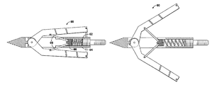
- FIG. 1 is a cross sectional side view of a broadhead according to a first embodiment of the present invention with the blade members in a retracted position;
- FIG. 2 is a view similar to FIG. 1 with the blade members in an extended position
- FIG. 3 is a cross sectional side view of a broadhead according to a second embodiment of the present invention with the blade members in a retracted position;
- FIG. 4 is a view similar to FIG. 3 with the blade members in an extended position
- FIG. 5 is a cross sectional side view of a broadhead according to a third embodiment of the present invention with the blade members in a retracted position;
- FIG. 6 is a view similar to FIG. 5 with the blade members in an extended position
- FIG. 7 is a cross sectional side view of a broadhead according to a fourth embodiment of the present invention with the blade members in a retracted position;
- FIG. 8 is a view similar to FIG. 8 with the blade members in an extended position
- an arrowhead according to one embodiment of the invention is generally indicated at 10 .
- This type of arrowhead is generally referred to as a broadhead.
- the arrowhead 10 includes a generally cylindrical body or ferrule 12 .
- a pointed tip 14 is formed at the forward end of the ferrule 12 and an attachment portion 16 is formed at the rearward end of the ferrule 12 .
- the portion between the ends may be called a ferrule body.
- the arrowhead 10 includes at least one blade member 20 movably coupled to the ferrule 12 for movement between a retracted position, as shown in FIG. 1 , and an extended position, as shown in FIG. 2 .
- blade members 20 are provided in generally symmetrically opposite pairs, e.g. two or four blade members spaced equidistantly in a rotational sense about the ferrule 12 , though an odd number is also possible.
- a front end 22 of each blade member 20 is movably coupled to the ferrule 12 nearer to the tip 14 than the attachment portion 16 . In the retracted position, the length of the blade member 20 is disposed along side of or adjacent to the ferrule 12 .
- the blade member 20 In the extended position, the blade member 20 is generally rotated forwardly so that a rear end 24 of the blade member 20 is spaced apart from the ferrule 12 . In the retracted position, the rear end 24 of the blade member may be said to be spaced from the ferrule 12 by a first distance and in the extended position the rear end 24 may be said to spaced from the ferrule by a distance greater than the first distance.
- the front end 22 of the blade member 20 is pivotally coupled to the ferrule 12 for movement about a fixed pivot 26 between the retracted and extended positions.
- a tab 28 extends outwardly from the front end 22 of each blade member 20 and contacts an abutting surface 30 on the ferrule to limit outward travel for the blade member 20 and define the extended position of the blade member 20 .
- the travel limit provided by the tab 28 and abutting surface 30 may be provided in other ways, or there may not be a travel limit.
- any position of the blade members 20 wherein the rear ends 24 are spaced from the ferrule by a distance greater than the first distance may be considered to be the extended position even if the travel limit is not reached.
- FIGS. 1 and 2 are cross sectional views and the forward ends of the blade members are disposed in a slot formed in the ferrule body.
- the slot may have a different shape than illustrated, and may allow more of the blade members to nest into the slot in the retracted position.
- a biasing member 40 continuously biases each blade member toward the extended position.
- the ferrule 12 has a pair of spring-receiving bores 18 defined therein and the biasing members 40 are coil springs disposed in the bores.
- the blade members 20 each further include an arm 42 that engages one of the springs 40 . In the retracted position, the arms 42 extend into the bores 18 and compress the springs 40 . The springs 40 expand, thereby pushing the arms 42 and blade members 20 outwardly as the blade members move to the extended position.
- a retaining element 50 initially retains the blade members 20 in the retracted position, as shown in FIG. 1 .
- the retaining element may take the form or a metal plastic or elastomer ring that engages recesses 52 in the second end of the blade members.
- the ring may be wrapped about the second end 24 of the blade members.
- each blade member may have its own retaining element.
- the retaining element may take other forms such as a lever or latch that initially retains the blade members 20 in the retracted position.
- the retaining element 50 is designed to disengage from the blade members 20 when the broadhead 10 punctures a target. For example, the material penetrated by the broadhead may push the retaining element 50 rearwardly to disengage it from the blade members.
- the arrowhead 10 is fixedly secured to an end of a longitudinally extending shaft forming a body of an arrow.
- the attachment portion 16 of the arrowhead 10 is a threaded male portion that is threaded into a threaded receiving hole formed in the end of the rod. It should be appreciated that other attachment arrangements may be provided for fixedly securing the arrowhead to the rod.
- the arrow 60 is fired toward an animal.
- the blade members 20 are preferably initially maintained in the retracted position as the arrow is in flight toward the animal.
- the retracted position reduces the size of the broadhead thereby increasing accuracy.
- the blade members 20 remain in the retracted position until the retaining element 50 is removed by the penetration.
- the blade members are then urged to the extended position due to the outward bias of the biasing members 40 .
- the blade members 20 collapse toward the retracted position to allow the arrow to continue progress through the bone.
- the blade members 20 return to the extended position due to the force applied by the biasing member 40 .
- the biasing member 40 is provided with a predetermined spring force that allows the blade members 20 to move to the retracted position as the ferrule 12 passes through the bone and to return to the extended position after the ferrule 12 has passed through the bone.
- the blade members 20 are in the extended position on either side of the bone to maximize the cutting surface of the arrowhead 10 through the soft flesh of the animal.
- FIGS. 3 and 4 a second embodiment of an arrowhead according to the present invention is generally shown at 60 .
- This embodiment is similar to the embodiment of FIGS. 1 and 2 .
- the biasing member 62 is disposed in a central axial bore of the ferrule 64 .
- the biasing member 62 engages a sliding element 66 which is also disposed in the bore.
- Articulating arms 68 interconnect the sliding element 66 with the blade members so as to bias them from the retracted position shown in FIG. 3 to the extended position shown in FIG. 4 .
- a third embodiment of an arrowhead according the present invention is generally shown as 70 .
- This embodiment differs from the earlier embodiments in that the biasing member 72 is disposed in a coaxial bore adjacent the forward end of the ferrule 74 .
- the biasing member is illustrated as a coil spring which engages a sliding element 76 also disposed in the bore.
- the sliding element 76 engages inwardly extending tabs 78 on the blade members. These tabs 78 extend inwardly from the pivotal connection between the blade members and the ferrule. By pushing rearwardly on the tabs 78 , the sliding element 76 urges the blade members outwardly from the retractable position shown in FIG. 5 to the extended position shown in FIG. 6 .
- the blade members in this embodiment have a somewhat different shape than the earlier embodiments. The blade shapes in all of the embodiments of the present invention may be altered from the illustrated versions.
- the biasing member takes the form of a pair of leaf springs that urge the blade members outwardly from the retractable position shown in FIG. 7 to the extended position shown in FIG. 8 .
- the biasing members may also take other forms, for example, the leaf springs may interconnect with the ferrule body ahead of the pivotal interconnection between the blade members and the ferrule and extend rearwardly to a position between the blade members.
- Other versions will also be clear to those of skill in the art.
- the blade members may be disposed more closely to the ferrule in the retractable position than illustrated in the various embodiments.
- the blade members may also be shaped so as to nest more closely to the ferrule and/or the ferrule body may have slots into which the blade members are partially disposed when in the retractable position.
- the various embodiments of the present invention utilize only the biasing member or members to urge and hold the blade members into the extended position.
- No latch or locking element is provided to hold the blade members in the extended position. Therefore, the blade members are free to move back to the retracted position when the arrowhead encounters a dense material such as bone.
Landscapes
- Engineering & Computer Science (AREA)
- General Engineering & Computer Science (AREA)
- Mechanical Coupling Of Light Guides (AREA)
Abstract
Description
Claims (17)
Priority Applications (1)
| Application Number | Priority Date | Filing Date | Title |
|---|---|---|---|
| US12/168,189 US8043177B2 (en) | 2008-07-07 | 2008-07-07 | Arrowhead having collapsible and outwardly biased blades |
Applications Claiming Priority (1)
| Application Number | Priority Date | Filing Date | Title |
|---|---|---|---|
| US12/168,189 US8043177B2 (en) | 2008-07-07 | 2008-07-07 | Arrowhead having collapsible and outwardly biased blades |
Publications (2)
| Publication Number | Publication Date |
|---|---|
| US20100004078A1 US20100004078A1 (en) | 2010-01-07 |
| US8043177B2 true US8043177B2 (en) | 2011-10-25 |
Family
ID=41464816
Family Applications (1)
| Application Number | Title | Priority Date | Filing Date |
|---|---|---|---|
| US12/168,189 Active 2030-03-29 US8043177B2 (en) | 2008-07-07 | 2008-07-07 | Arrowhead having collapsible and outwardly biased blades |
Country Status (1)
| Country | Link |
|---|---|
| US (1) | US8043177B2 (en) |
Cited By (24)
| Publication number | Priority date | Publication date | Assignee | Title |
|---|---|---|---|---|
| US20120165142A1 (en) * | 2010-12-22 | 2012-06-28 | Grace Engineering Corp. | Mechanical broadhead |
| US20120178560A1 (en) * | 2011-01-11 | 2012-07-12 | Grace Engineering Corp. | Mechanical broadhead |
| US20140128186A1 (en) * | 2012-11-04 | 2014-05-08 | Timothy Lee Treto | Mechanical Broadheads with Hinged Rear Blades |
| US20140155202A1 (en) * | 2012-11-30 | 2014-06-05 | Paul A. Young | Automatic opening mechanical archery broadhead |
| US8905874B2 (en) | 2013-03-18 | 2014-12-09 | Brian Sullivan | Broadhead arrowhead with two-stage expansion |
| US9052170B1 (en) | 2013-10-04 | 2015-06-09 | Slick Hunting Products Inc | Actuating bird-wing arrow blade |
| US9341451B1 (en) * | 2013-10-04 | 2016-05-17 | Slick Hunting Products Inc. | Actuating bird-wing arrow blade |
| US9372056B2 (en) | 2013-03-18 | 2016-06-21 | Brian Sullivan | Broadhead arrowhead with two-stage expansion |
| US9526234B2 (en) | 2014-12-19 | 2016-12-27 | David R. Harshberger | Bowfishing arrow |
| US9803962B2 (en) | 2015-10-30 | 2017-10-31 | Bear Archery, Inc. | Broadhead retaining clip |
| US20180128584A1 (en) * | 2016-11-04 | 2018-05-10 | Barnett Outdoors, Llc | Broadhead deployment/locking system and method |
| US10295321B2 (en) | 2016-11-17 | 2019-05-21 | Yvonne Louise Braden | Projectile tracking device |
| US10295316B2 (en) | 2017-07-21 | 2019-05-21 | Jacob WUKIE | Variable cutting diameter arrowhead |
| US10415940B2 (en) | 2017-07-25 | 2019-09-17 | Brian E. Sullivan | Over center expanding arrowhead |
| US10598469B2 (en) | 2017-03-28 | 2020-03-24 | Mickey Don Lankford | Forward deploying, rear activated, delayed opening, broadhead |
| USD924351S1 (en) | 2017-01-09 | 2021-07-06 | Tog-Ip Llc | Arrowhead |
| US11125542B2 (en) * | 2018-03-12 | 2021-09-21 | Troy Allen Motz | Rear deploying broadhead |
| US20220244025A1 (en) * | 2019-03-11 | 2022-08-04 | Troy Allen Motz | Rear Deploying Broadhead |
| US11549791B1 (en) * | 2020-10-22 | 2023-01-10 | Arrowds Llc | Broadhead blade impact energy transfer apparatus and method |
| US11774222B1 (en) * | 2021-09-07 | 2023-10-03 | Matthew Futtere | Alternative broadhead blade lock and release apparatus and method |
| US11852454B2 (en) * | 2021-11-17 | 2023-12-26 | Matthew Futtere | Broadhead blade gravity lock and inertia release apparatus and method |
| US12264904B2 (en) | 2023-08-10 | 2025-04-01 | Bowmar Archery Llc | Variable cutting diameter arrowhead |
| US12467726B2 (en) | 2018-12-23 | 2025-11-11 | Evolution Outdoors LLC | Multi-functional broadhead fixed and mechanical |
| US20250354785A1 (en) * | 2023-11-09 | 2025-11-20 | TrikaUSA Inc. | Broadhead |
Families Citing this family (13)
| Publication number | Priority date | Publication date | Assignee | Title |
|---|---|---|---|---|
| US20090203477A1 (en) * | 2008-02-12 | 2009-08-13 | Mizek Robert S | Blade opening arrowhead |
| US8016704B1 (en) * | 2008-03-20 | 2011-09-13 | EP Hunting LLC | Arrowhead with pivoting blade |
| US8133138B1 (en) * | 2009-05-14 | 2012-03-13 | Luke Hannah | Archery broadhead |
| US8182378B1 (en) * | 2010-01-11 | 2012-05-22 | Matthew Futtere | Compressible cutting width broadhead apparatus and method |
| US8128521B1 (en) | 2010-08-11 | 2012-03-06 | Russell Karl Ulmer | Mechanical broadhead with pivoting, interlocking blades |
| WO2012125444A1 (en) * | 2011-03-11 | 2012-09-20 | Asherman Richard Edward | Pivoting cutting elements for projectiles |
| US9212873B2 (en) | 2013-03-08 | 2015-12-15 | Christopher Michael HARTMAN | Second cut arrow shaft extension |
| US10514238B2 (en) * | 2014-11-21 | 2019-12-24 | II John Razmus | Bowfishing arrow with a quick-release arrowhead |
| US10041772B1 (en) * | 2015-01-02 | 2018-08-07 | Kevin M. Sullivan | Fish harvesting head |
| US10718595B2 (en) * | 2016-03-23 | 2020-07-21 | Digital to Definitive, LLC | Quick-detachable multi-purpose accessory mounting platform |
| US20200292285A1 (en) * | 2017-03-23 | 2020-09-17 | Digital to Definitive, LLC | Quick-detachable multi-purpose accessory mounting platform |
| US11118878B2 (en) * | 2018-11-30 | 2021-09-14 | Nicola Albanese | Apparatus and method for broadhead archery |
| US10921102B1 (en) * | 2018-11-30 | 2021-02-16 | Nicola Albanese | Apparatus and method for broadhead archery |
Citations (12)
| Publication number | Priority date | Publication date | Assignee | Title |
|---|---|---|---|---|
| US3036395A (en) * | 1959-06-11 | 1962-05-29 | Erlo C Nelson | Releasing fish point |
| US3036396A (en) | 1959-08-31 | 1962-05-29 | Swails Roy | Retractable arrow |
| US4099720A (en) | 1976-02-23 | 1978-07-11 | Zeren Joseph D | Expanding arrowhead |
| US4973060A (en) * | 1990-03-28 | 1990-11-27 | Herzing Mathew J | Arrowhead with expandable blades |
| US5879252A (en) | 1994-01-21 | 1999-03-09 | Johnson; Gregory G. | Arrowhead |
| US6270435B1 (en) | 2000-07-17 | 2001-08-07 | Arvid Ames | Arrowhead |
| US6287224B1 (en) | 1997-04-11 | 2001-09-11 | Liechty, Ii Victor Jay | Non-consumable blade retention for blade-opening arrowheads |
| US6554727B1 (en) * | 2001-03-16 | 2003-04-29 | The Game Tracker, Inc. | Deflection-resistant arrowhead having both fixed and mechanically expandable blades |
| US6793596B1 (en) | 2003-12-22 | 2004-09-21 | Kevin Michael Sullivan | Arrowhead with pivotable blades |
| US6830523B1 (en) | 2004-01-28 | 2004-12-14 | 2Xj Enterprises, Inc. | Mechanical broadhead arrowhead |
| US7311622B1 (en) | 2004-11-16 | 2007-12-25 | Matthew Futtere | Wire broadhead apparatus and method |
| US7713152B1 (en) * | 2006-12-26 | 2010-05-11 | Lynn A. Tentler | Arrowhead with unfolding blades |
-
2008
- 2008-07-07 US US12/168,189 patent/US8043177B2/en active Active
Patent Citations (13)
| Publication number | Priority date | Publication date | Assignee | Title |
|---|---|---|---|---|
| US3036395A (en) * | 1959-06-11 | 1962-05-29 | Erlo C Nelson | Releasing fish point |
| US3036396A (en) | 1959-08-31 | 1962-05-29 | Swails Roy | Retractable arrow |
| US4099720A (en) | 1976-02-23 | 1978-07-11 | Zeren Joseph D | Expanding arrowhead |
| US4973060A (en) * | 1990-03-28 | 1990-11-27 | Herzing Mathew J | Arrowhead with expandable blades |
| US5879252A (en) | 1994-01-21 | 1999-03-09 | Johnson; Gregory G. | Arrowhead |
| US6287224B1 (en) | 1997-04-11 | 2001-09-11 | Liechty, Ii Victor Jay | Non-consumable blade retention for blade-opening arrowheads |
| US6758774B2 (en) | 1997-04-11 | 2004-07-06 | Liechty, Ii Victor Jay | Arrowhead with recessed collar |
| US6270435B1 (en) | 2000-07-17 | 2001-08-07 | Arvid Ames | Arrowhead |
| US6554727B1 (en) * | 2001-03-16 | 2003-04-29 | The Game Tracker, Inc. | Deflection-resistant arrowhead having both fixed and mechanically expandable blades |
| US6793596B1 (en) | 2003-12-22 | 2004-09-21 | Kevin Michael Sullivan | Arrowhead with pivotable blades |
| US6830523B1 (en) | 2004-01-28 | 2004-12-14 | 2Xj Enterprises, Inc. | Mechanical broadhead arrowhead |
| US7311622B1 (en) | 2004-11-16 | 2007-12-25 | Matthew Futtere | Wire broadhead apparatus and method |
| US7713152B1 (en) * | 2006-12-26 | 2010-05-11 | Lynn A. Tentler | Arrowhead with unfolding blades |
Cited By (35)
| Publication number | Priority date | Publication date | Assignee | Title |
|---|---|---|---|---|
| US8449415B2 (en) * | 2010-12-22 | 2013-05-28 | Grace Engineering Corp. | Mechanical broadhead |
| US20120165142A1 (en) * | 2010-12-22 | 2012-06-28 | Grace Engineering Corp. | Mechanical broadhead |
| US20120178560A1 (en) * | 2011-01-11 | 2012-07-12 | Grace Engineering Corp. | Mechanical broadhead |
| US8449416B2 (en) * | 2011-01-11 | 2013-05-28 | Grace Engineering Corp. | Mechanical broadhead |
| US9017191B2 (en) * | 2012-11-04 | 2015-04-28 | Timothy Lee Treto | Mechanical broadheads with hinged rear blades |
| US20140128186A1 (en) * | 2012-11-04 | 2014-05-08 | Timothy Lee Treto | Mechanical Broadheads with Hinged Rear Blades |
| US20140128185A1 (en) * | 2012-11-04 | 2014-05-08 | Timothy Lee Treto | Mechanical Broadheads with Hinged Front Blades |
| US8926457B2 (en) * | 2012-11-04 | 2015-01-06 | Timothy Lee Treto | Mechanical broadheads with hinged front blades |
| US20140155202A1 (en) * | 2012-11-30 | 2014-06-05 | Paul A. Young | Automatic opening mechanical archery broadhead |
| US8894519B2 (en) * | 2012-11-30 | 2014-11-25 | Paul A. Young | Automatic opening mechanical archery broadhead |
| US8905874B2 (en) | 2013-03-18 | 2014-12-09 | Brian Sullivan | Broadhead arrowhead with two-stage expansion |
| US9372056B2 (en) | 2013-03-18 | 2016-06-21 | Brian Sullivan | Broadhead arrowhead with two-stage expansion |
| US9052170B1 (en) | 2013-10-04 | 2015-06-09 | Slick Hunting Products Inc | Actuating bird-wing arrow blade |
| US9341451B1 (en) * | 2013-10-04 | 2016-05-17 | Slick Hunting Products Inc. | Actuating bird-wing arrow blade |
| US9526234B2 (en) | 2014-12-19 | 2016-12-27 | David R. Harshberger | Bowfishing arrow |
| US9803962B2 (en) | 2015-10-30 | 2017-10-31 | Bear Archery, Inc. | Broadhead retaining clip |
| US20180128584A1 (en) * | 2016-11-04 | 2018-05-10 | Barnett Outdoors, Llc | Broadhead deployment/locking system and method |
| US10281250B2 (en) * | 2016-11-04 | 2019-05-07 | Barnett Outdoors, Llc | Broadhead deployment/locking system and method |
| US10295321B2 (en) | 2016-11-17 | 2019-05-21 | Yvonne Louise Braden | Projectile tracking device |
| US10612900B2 (en) | 2016-11-17 | 2020-04-07 | Yvonne Louise Braden | Projectile tracking with stop device |
| USD924351S1 (en) | 2017-01-09 | 2021-07-06 | Tog-Ip Llc | Arrowhead |
| US10598469B2 (en) | 2017-03-28 | 2020-03-24 | Mickey Don Lankford | Forward deploying, rear activated, delayed opening, broadhead |
| US10295316B2 (en) | 2017-07-21 | 2019-05-21 | Jacob WUKIE | Variable cutting diameter arrowhead |
| US10415940B2 (en) | 2017-07-25 | 2019-09-17 | Brian E. Sullivan | Over center expanding arrowhead |
| US11125542B2 (en) * | 2018-03-12 | 2021-09-21 | Troy Allen Motz | Rear deploying broadhead |
| US12467726B2 (en) | 2018-12-23 | 2025-11-11 | Evolution Outdoors LLC | Multi-functional broadhead fixed and mechanical |
| US20220244025A1 (en) * | 2019-03-11 | 2022-08-04 | Troy Allen Motz | Rear Deploying Broadhead |
| US11725914B2 (en) * | 2019-03-11 | 2023-08-15 | Troy Allen Motz | Rear deploying broadhead |
| US11549791B1 (en) * | 2020-10-22 | 2023-01-10 | Arrowds Llc | Broadhead blade impact energy transfer apparatus and method |
| US20230384066A1 (en) * | 2021-08-11 | 2023-11-30 | Troy Allen Motz | Rear Deploying Broadhead |
| US11774222B1 (en) * | 2021-09-07 | 2023-10-03 | Matthew Futtere | Alternative broadhead blade lock and release apparatus and method |
| US11852454B2 (en) * | 2021-11-17 | 2023-12-26 | Matthew Futtere | Broadhead blade gravity lock and inertia release apparatus and method |
| US12264904B2 (en) | 2023-08-10 | 2025-04-01 | Bowmar Archery Llc | Variable cutting diameter arrowhead |
| US20250354785A1 (en) * | 2023-11-09 | 2025-11-20 | TrikaUSA Inc. | Broadhead |
| US12498205B2 (en) * | 2023-11-09 | 2025-12-16 | Trika Usa Inc. | Broadhead |
Also Published As
| Publication number | Publication date |
|---|---|
| US20100004078A1 (en) | 2010-01-07 |
Similar Documents
| Publication | Publication Date | Title |
|---|---|---|
| US8043177B2 (en) | Arrowhead having collapsible and outwardly biased blades | |
| US8905874B2 (en) | Broadhead arrowhead with two-stage expansion | |
| US6287224B1 (en) | Non-consumable blade retention for blade-opening arrowheads | |
| US9372056B2 (en) | Broadhead arrowhead with two-stage expansion | |
| US8926457B2 (en) | Mechanical broadheads with hinged front blades | |
| TWI644077B (en) | Broadhead | |
| US8128521B1 (en) | Mechanical broadhead with pivoting, interlocking blades | |
| US20140179467A1 (en) | Expandable broadhead with chisel tip | |
| US8007382B1 (en) | Expandable arrow broadhead with two-piece folding cutting blades | |
| US9335135B2 (en) | Rear-deploying mechanical broadhead | |
| US9329006B1 (en) | Magnetic blade retainer for a broadhead | |
| US8974327B2 (en) | Hunting arrowhead having fixed and expandable blades | |
| US10295316B2 (en) | Variable cutting diameter arrowhead | |
| US10619982B2 (en) | Broadhead with multiple deployable blades | |
| WO2014107308A1 (en) | Expandable broadhead having tip formed as an integral portion of a steel or stainless steel ferrule | |
| US8133138B1 (en) | Archery broadhead | |
| US11118878B2 (en) | Apparatus and method for broadhead archery | |
| US9239216B2 (en) | Arrowhead | |
| US9091515B1 (en) | Arrowhead and arrow | |
| US8096905B1 (en) | Archery broadhead with replaceable blades | |
| US9052170B1 (en) | Actuating bird-wing arrow blade | |
| US8475302B1 (en) | Broad tail hunting arrow | |
| US11137235B2 (en) | Broadhead for bow hunting | |
| US20220394960A1 (en) | Fishing head with retractable blades for bowfishing | |
| US10598469B2 (en) | Forward deploying, rear activated, delayed opening, broadhead |
Legal Events
| Date | Code | Title | Description |
|---|---|---|---|
| STCF | Information on status: patent grant |
Free format text: PATENTED CASE |
|
| CC | Certificate of correction | ||
| FPAY | Fee payment |
Year of fee payment: 4 |
|
| MAFP | Maintenance fee payment |
Free format text: PAYMENT OF MAINTENANCE FEE, 8TH YR, SMALL ENTITY (ORIGINAL EVENT CODE: M2552); ENTITY STATUS OF PATENT OWNER: SMALL ENTITY Year of fee payment: 8 |
|
| FEPP | Fee payment procedure |
Free format text: MAINTENANCE FEE REMINDER MAILED (ORIGINAL EVENT CODE: REM.); ENTITY STATUS OF PATENT OWNER: SMALL ENTITY |
|
| FEPP | Fee payment procedure |
Free format text: 11.5 YR SURCHARGE- LATE PMT W/IN 6 MO, SMALL ENTITY (ORIGINAL EVENT CODE: M2556); ENTITY STATUS OF PATENT OWNER: SMALL ENTITY |
|
| MAFP | Maintenance fee payment |
Free format text: PAYMENT OF MAINTENANCE FEE, 12TH YR, SMALL ENTITY (ORIGINAL EVENT CODE: M2553); ENTITY STATUS OF PATENT OWNER: SMALL ENTITY Year of fee payment: 12 |
|
| AS | Assignment |
Owner name: FUTTERE, MATTHEW, TEXAS Free format text: ASSIGNMENT OF ASSIGNORS INTEREST;ASSIGNOR:FLANAGAN, EDWARD;REEL/FRAME:066212/0122 Effective date: 20240123 |
|
| IPR | Aia trial proceeding filed before the patent and appeal board: inter partes review |
Free format text: TRIAL NO: IPR2024-00401 Opponent name: BOWMAR ARCHERY LLC Effective date: 20240108 |
|
| AS | Assignment |
Owner name: VETERAN INNOVATIVE PRODUCTS LLC, TEXAS Free format text: ASSIGNMENT OF ASSIGNORS INTEREST;ASSIGNOR:FLANAGAN, EDWARD;REEL/FRAME:072281/0711 Effective date: 20190418 |