US8042448B1 - Firearm muzzle attachment - Google Patents
Firearm muzzle attachment Download PDFInfo
- Publication number
- US8042448B1 US8042448B1 US12/360,010 US36001009A US8042448B1 US 8042448 B1 US8042448 B1 US 8042448B1 US 36001009 A US36001009 A US 36001009A US 8042448 B1 US8042448 B1 US 8042448B1
- Authority
- US
- United States
- Prior art keywords
- compensator
- muzzle
- region
- recited
- port
- Prior art date
- Legal status (The legal status is an assumption and is not a legal conclusion. Google has not performed a legal analysis and makes no representation as to the accuracy of the status listed.)
- Active, expires
Links
Images


Classifications
-
- F—MECHANICAL ENGINEERING; LIGHTING; HEATING; WEAPONS; BLASTING
- F41—WEAPONS
- F41A—FUNCTIONAL FEATURES OR DETAILS COMMON TO BOTH SMALLARMS AND ORDNANCE, e.g. CANNONS; MOUNTINGS FOR SMALLARMS OR ORDNANCE
- F41A21/00—Barrels; Gun tubes; Muzzle attachments; Barrel mounting means
- F41A21/32—Muzzle attachments or glands
- F41A21/34—Flash dampers
-
- F—MECHANICAL ENGINEERING; LIGHTING; HEATING; WEAPONS; BLASTING
- F41—WEAPONS
- F41A—FUNCTIONAL FEATURES OR DETAILS COMMON TO BOTH SMALLARMS AND ORDNANCE, e.g. CANNONS; MOUNTINGS FOR SMALLARMS OR ORDNANCE
- F41A21/00—Barrels; Gun tubes; Muzzle attachments; Barrel mounting means
- F41A21/32—Muzzle attachments or glands
- F41A21/36—Muzzle attachments or glands for recoil reduction ; Stabilisators; Compensators, e.g. for muzzle climb prevention
Definitions
- Muzzle attachments are utilized on firearms for various enhancements thereof.
- a muzzle attachment such as a compensator or a flash suppressor is commonly attached to muzzles by the operator or owner of the firearm.
- Expanding combusting gas from a cartridge used to propel a bullet can generally be utilized for various purposes, such as providing an upward thrust of the gas, thereby providing a counterbalance downward force upon the muzzle to prevent muzzle lift.
- firearms tend to raise in a twelve o'clock direction after firing due to the various force dynamics of the accelerating bullet and the position of the barrel, as well as the ergonomic factors of the position of the rifle upon the shooter.
- a compensator is to suppress a flash.
- a straight-cut barrel without any form of compensation but merely having a circular opening can create a muzzle flash, which can be undesirable in certain law enforcement and military applications where the shooter will not want to give away their location.
- a muzzle flash can be distracting for a shooter.
- certain types of flash suppressors have been utilized, such as offsetting Gore-Tex channels.
- such a symmetrical design emitting gas rather symmetrically in the vertically upward and downward direction will not have an effect on preventing muzzle rise.
- the exiting vortexing gas generally must be at the longitudinally forward-most region.
- Any form of lift compensation then, in one form, would be positioned longitudinally rearward of such a flash suppressing vortexing region.
- providing such a lift compensation region having emitting gas would, on the face of it, appear to emit the pre-combusted flame producing gas, which would thwart the effect of the vortexing flash suppressing region, which is further downstream on the muzzle.
- the applicants have found a suitable muzzle attachment which provides for flash suppression and the lowering of muzzle flip.
- a muzzle compensator having a first and second lateral region and forward and rearward longitudinal regions.
- the compensator further having an upper and lower vertical region.
- the muzzle compensator is configured to attach to a muzzle of a firearm such as by way of a threaded attachment in one form.
- the muzzle compensator has a center bore having a center bore axis.
- the compensator comprises a vortexing region having a plurality of vortex channels with a center axis that are offset from the center bore axis and substantially perpendicular thereto. the vortexing region provides flash suppression qualities which is desirable for suppressing a flash.
- the muzzle compensator further has a compensator region having a first pair of first and second longitudinally rearward slanted surfaces defining in part first and second lateral compensation ports. There are further first and second counter lift surfaces positioned in the first and second lateral regions respectively. The first and second counter lift surfaces being in communication with first and second access vents which provide communication to the center bore.
- the muzzle compensator has a second pair of longitudinally rearward slanted surfaces positioned on the first and second lateral regions of the muzzle compensator defining in party third and fourth lateral compensation ports.
- the first access vent provides communication between the first and third lateral compensation ports.
- the second access vent provides communication between the second and fourth lateral compensation ports.
- the width of the second access vent is greater than the width of the first access vent.
- the second access vent is at least 0.025′′ larger in width than the first access vent where the firearm has a right-handed twist barrel.
- a muzzle device with first and second laterally opposing port openings defined by first and second interior edge services. There are further third and fourth longitudinally opposing port openings further defined by third and fourth interior edge surfaces respectfully.
- a first access vent is provided extending in a longitudinal direction and defined by first and second edge surfaces. This first access vent provides communication between the first and third port openings. There is further a second access vent defined by third and fourth interior edge surfaces and this second access vent extends in the longitudinal direction and provides communication between the second and fourth compensator ports.
- the muzzle device has a first counter lift surface positioned adjacent to the first access vent a horizontal component thereof configured to have pressurized gas impinge thereupon when exiting the first access vent. Further there is a second counter lift surface positioned adjacent to the second access vent, the second counter lift surface having a horizontal component configured to have the compressed gas impinge thereupon when exiting the second access vent.
- the muzzle device is configured where the first access vent has a greater open cross-sectional area than the second access vent.
- the first, second, third and fourth compensator ports can each have longitudinally rearward slanted services operatively configured to direct the expanding gas in a longitudinally rearward direction. In this configuration the distance between the first and second interior edge surfaces defining the first access vent is greater than the distance between the third and fourth interior edge surfaces defining the second axis vent.
- the muzzle device first counter lift surface can provide a greater rotational torque than the second counter lift surface when expanding gas exits through the first and second access vents.
- a flash suppression region is positioned longitudinally forward of the first, second, third and fourth compensator vents.
- a plurality of channels are defined in one form having channel center axes that are offset from a longitudinal center axis of the compensator member.
- a baffle can be interposed between the first and second compensator ports and the flash suppression region. In experimentation the baffle can be less than 0.090 inches in diameter than the size of a bullet designed to pass through the muzzle device and is approximately 0.060 inches in diameter greater than the size of a prescribed bullet diameter for use with the muzzle device
- FIG. 1A shows an isometric view of the muzzle device attached to an upper assembly of a rifle
- FIG. 1B shows a side view of the muzzle device with the upper assembly of the rifle
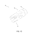
- FIG. 1C shows an isometric view and a longitudinally forward region of the muzzle device
- FIG. 2 shows a lateral view of the muzzle device taken from the left lateral side from the orientation of a shooter behind the muzzle;
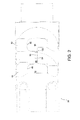
- FIG. 3 shows a front view in the longitudinal direction of the muzzle device showing the various channel regions of the flash suppressor region
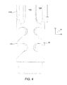
- FIG. 4 shows a top view of the muzzle device
- FIG. 5 shows an isometric view of the muzzle device taken from a longitudinally rearward and vertically upward vantage point
- FIG. 6 shows an opposing lateral view to that of FIG. 2 where the vantage point of this lateral view is from the right-hand lateral portion of the muzzle device from the perspective of a shooter positioned behind the muzzle device in the longitudinal direction;
- FIG. 7 shows a top view of the muzzle device taken downstream of the muzzle from a vertically upward vantage point
- FIG. 8 shows a bottom view of the muzzle device
- FIG. 9 shows a side view of the lateral direction on the left-hand side of the muzzle device attached to a barrel
- FIG. 10 shows the muzzle device attached to a barrel from a left hand lateral side view and slightly longitudinal rearward vantage point
- FIG. 11 shows a portion of the upper assembly and barrel attached to the muzzle device illustrating the concepts of the torques acting thereupon the barrel and the counter-torques provided by the counter lift surfaces of the muzzle device;
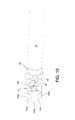
- FIG. 12 shows a second embodiment of an example of the muzzle device
- FIG. 13 shows a top view of the second embodiment of the muzzle device
- FIG. 14 shows an isometric view of the second embodiment taken at an upward and longitudinal forward vantage point
- FIG. 15 shows another isometric view of the second embodiment taken from a longitudinally forward and upward vantage point on the right-hand lateral side of the device.
- FIG. 1A there is shown an environmental view where the muzzle device 20 is shown attached to a barrel member 18 .
- the axis 12 indicates a longitudinal axis pointing in a longitudinally forward direction.
- the axis 14 indicates a vertical direction
- the axes system 10 as shown in FIG. 4 shows the lateral axis 16 pointing in a first lateral direction which in one form is to the right-hand portion of the muzzle device 20 .
- the muzzle device an attachment region 22 , a compensator region 24 , and a vortex/flash suppression region 26 .
- the desirable arrangement of the compensator region 24 and the vortex region 26 provides a desirable distribution of the exhausting muzzle gas, which is described further below.
- FIG. 1A in one form shows a barrel 18 which is a part of an upper assembly 7 which can be an upper assembly for an AR-15.
- the muzzle device 20 could be attached to a variety of types of firearms, and not only rifles but further, for example, pistols.
- the upper assembly 7 for example, is configured to be attached to a lower assembly to complete the firearm.
- the upper assembly comprises a gas block 9 , a hand guard 11 and an upper receiver 13 .
- FIG. 1B shows a side view of the muzzle device 20 .
- the attachment region 22 as described immediately below is threaded to the longitudinally forward portion of the barrel 18 .
- the muzzle device 20 is particularly advantageous for suppressing flashes by way of the flash suppression region 26 , and further particularly conducive for reducing muzzle flip and overall felt recoil, which is accomplished at least in part by the compensator region 24 .
- access vents 90 and 91 provide in part communication to substantially horizontal surfaces (in one form) which reduce muzzle flip.
- the longitudinally rearward slanting surfaces 44 and 46 as well as 64 and 66 direct the expanding gas longitudinally rearwardly to reduce felt recoil upon the firearm for the shooter.
- This general introduction is provided because in one form, the compensator region 24 positioned longitudinally rearward to the flash suppression region 26 has proven to have a surprising effect of maintaining a flash suppression device by way of producing a vortex-like action out of the channel regions 128 (described further herein with reference to FIG. 3 ) and maintaining a compensator like effect with the various surfaces in the compensator region 24 .
- the particular arrangement of the compensator region 24 and the flash suppression region 26 provides a flash suppression device even though the open first and second port openings ( FIGS. 2 and 6 ) 54 and 56 as well as 84 and 86 of the compensator region are longitudinally rearward with respect to the flash suppression region. Further analysis and description of this phenomenon will be described after a detailed discussion of various example forms of the muzzle device 20 .
- FIG. 5 there is shown a longitudinally rearward isometric view of the muzzle device 20 where the attachment region 22 is shown.
- the interior surface 32 is threaded to receive a male threading, for example, a barrel 18 as shown in FIG. 1 .
- the attachment region could be otherwise attached to the muzzle region of the barrel by way of a permanent attachment such as welding or the like.
- a torque receiving surface 34 is supplied. This surface is common in the industry for providing a wrench-like device for supplying a sufficient amount of torque to attach the muzzle device 20 to a barrel in one form.
- the compensator region comprises a first compensator port 40 and FIG. 2 illustrates a second compensator port 42 .
- the compensator ports are in one form configured to direct gas in a longitudinal rearward direction.
- FIG. 8 there is a bottom view of the muzzle device 20 with a first lateral longitudinally rearward slanted surface 44 and a second lateral longitudinally rearward slanted surface 46 . These surfaces 44 and 46 are configured to redirect the gas in a longitudinally rearward direction, as shown by arrows 50 and 52 .
- there is an interior surface edge 48 and a corresponding surface edge 49 in FIG. 6 which defines the first and second port openings 54 and 56 which are in communication with the first and second compensator ports 40 and 42 .
- a third lateral compensation port 60 and a fourth lateral compensation port 62 in one form there is shown a third lateral compensation port 60 and a fourth lateral compensation port 62 .
- the third and fourth lateral longitudinally rearward slanted surfaces 64 and 66 are provided to redirect gas in a longitudinal rearward fashion in like manner as the surfaces 44 and 46 described above (see FIG. 8 ).
- the first, second, third and fourth lateral compensation ports each further comprise the longitudinally rearward surfaces 70 , 72 , 74 and 76 as shown in FIG. 8 which aid in the direction of the gas in the longitudinally rearward direction.
- the interior surface edges 78 and 80 define the third and fourth port openings 84 and 86 .
- the compensator region in part comprises (in one form at least) two pairs of lateral compensation ports that are positioned in the opposing lateral regions of the muzzle device 20 .
- access vents which in one form provide communication between port openings on the corresponding lateral locations of the muzzle device.
- FIG. 6 there is shown the first and third port openings 54 and 84 .
- the edge surfaces indicated at 90 and 91 in one form define a first access vent 92 which provides communication between the first and third port openings 54 and 84 .
- FIG. 2 there is shown interior edge surfaces 94 and 96 which in part define the second access vent 98 .
- the second counter lift surface 100 adjacent to the edge surface 96 is the second counter lift surface 100 .
- a first counter lift surface 99 on the opposing lateral side is a first counter lift surface 99 .
- FIG. 7 there is an isometric view of the muzzle device 20 attached to a barrel 18 , and this particular view is downstream of the muzzle taken from a vantage point above the centerline bore of the muzzle where it can be appreciated that the first and second counter lift surfaces 99 and 100 are positioned at opposing lateral regions (not necessarily directly opposite) of the muzzle device 20 .
- the second access vent 98 which is defined by the edge surfaces 94 and 96 (see also FIG. 5 for an isometric view), is defined by a vertical width 102 .
- the width 102 need not be uniform in the longitudinal direction along the edge surfaces 94 and 96 . But in general, the width 102 is less than the width 104 as shown in FIG. 6 , which defines the width opening of the first access vent 92 .
- the first access vent 92 is greater in a cross-sectional open area than the second access vent 98 as shown in FIG. 5 .
- a greater open region to the first counter lift surface 99 a greater amount of expanding gas can be ejected through the first access vent, thereby having greater effect of a counterforce upon the first counter lift surface 99 .
- the exterior surface of the bullet travels in a helical path as shown by the hatched line 110 in FIG. 11 .
- the bullet begins from rest and must accelerate not only in the longitudinal direction but also will have an angular acceleration.
- a bullet such as an 80 grain bullet may have a rotational velocity of several hundred thousand rotations per minute.
- a relatively light bullet compared to the mass of the gun can create a certain amount of counter torque upon the barrel which is transferred to the firearm.
- This counter torque produced from the bullet of course creates a net torquing effect illustrated by the torque vector 112 . Therefore, the first counter lift surface 99 ( FIG. 11 ) will have a slightly greater amount of gas acting thereupon than the second counter lift surface 100 ( FIG. 5 ) will produce a counter torque vector 114 , thereby reducing the propensity for the firearm to twist about the longitudinal axis during operation.
- first counter lift surface 99 is positioned slightly lower than the second counter lift surface 100 .
- these surfaces may not be offset, and the interior edge surface 90 as shown in FIG. 6 could simply be repositioned vertically higher.
- the flash suppression region 26 in one form is comprised of a plurality of longitudinal extensions 120 which are specifically denoted as 120 a , 120 b , 120 c , and 120 d.
- FIG. 11 there is a more close-up view of the flash suppression region 26 where the longitudinal extension 120 b will be described in detail with the understanding that the description is relevant to the other longitudinal extensions.
- a plurality of extensions can be utilized, of an amount less than three and greater than four.
- the general operation of the extensions is to create a rotating vortex-like action of the expanding gas.
- This is one form of a flash suppression technology, and other forms may be utilized.
- other forms such as the “birdcage” design could be incorporated in the broader scope.
- the first and second offset surfaces 124 and 126 are provided on the extension 120 b . Both of these surfaces have a component extending in the longitudinal direction.
- the embodiment as shown in FIG. 11 shows one form where the surfaces extend substantially directly along the longitudinal direction.
- FIG. 3 there is an end view looking down the muzzle.
- the barrel has an interior chamber 119 and an interior surface 121 .
- the interior surface 121 has lands and grooves which are configured to engage the outer surface of a bullet. As described above, the lands and grooves are most often rotated in a longitudinal direction to provide spin to the bullet, creating a torque indicated by the vector 112 in FIG. 11 .
- the interior chamber 119 provides not only the exit of the bullet, but the exit of expanding gases. It should be noted that the compressed gas leaving the bullet will exit to the various ports and chambers of the muzzle device 20 . Downstream of the bullet is the combustion gas from the most common combustible materials such as gunpowder or cordite. This combustion material passes through the interior chamber 119 of the barrel and in one form is simply exhausted out the muzzle of the barrel as in prior art devices.
- This expanded combusted and semi-combusted gas can provide utility for reducing the longitudinally rearward-felt recoil upon the firearm, reducing the lift of the muzzle during firing, reducing the rotational torque acting upon the firearm by the rotational acceleration of the bullet, and finally the pressure of the expanding gas can be utilized to aid in extinguishing a portion of the visible flame by way of the flash suppression region 26 .
- the first and second surfaces 124 and 126 are shown.
- the correlating surfaces on adjacent members will be utilized with the corresponding alpha character (e.g. “a”, “c”, or “d”).
- the adjacent longitudinal extensions 120 a and 120 b provide corresponding surfaces 126 a and 124 b .
- These sets of surfaces provide channel regions throughout the unit which are generally denoted at 128 a , 128 b , 128 c and 128 d . Each one of these channel regions provides a general central axis 130 a , 130 b , 130 c , and 130 d which are all offset from the center point 123 of the interior chamber 119 .
- gas generally traveling through the channel regions 128 will have a proximate center axis of travel along the axis 130 . Therefore, analyzing each of the channel regions 128 as a thruster, it can be appreciated that if the gas generally travels along the center axis 130 of each of the channel regions 128 , there could possibly be a counter-torque action upon the barrel, but moreover, these offset channel regions tend to produce a rotating vortexing-like exhaust of the gas which has a propensity to extinguish the flame of the gas that is still combusting, thereby reducing the net amount of lumens produced while firing a round.
- expanding gas will tend to expand directly radially outward from the center point 123 .
- the expanding gas will tend to take a nonlinear radially outward path but provide a certain amount of rotation, and present analysis indicates a more turbulent-like action to combust the not-yet fully combusted particulate matter.
- the dimension 134 can be approximately one half of an inch (plus or minus 10% in one form and plus or minus 20% in a broader scope).
- a half-inch longitudinal extension 120 provided a surprising result of suppressing a flame greater than a longer longitudinal extension of three-quarters of an edge.
- Present analysis by the applicants conjectures that the reason for this phenomenon could be that a longer longitudinal extension had the effect of igniting additional ignitable material from the gunpowder, or some derivatives of the gunpowder during the firing process, which produced radially extending sparks.
- baffle region 67 which in a preferred form is cylindrical having a center axis that is common with the center axis 123 of the muzzle as shown in FIG. 3 .
- This baffle 67 can be, for example, between 0.015-0.040 inches radially around the perimeter region of the bullet configured to pass therethrough.
- One preferred form of the baffle member is to provide a 0.030 inch clearance radially around the perimeter of the prescribed caliber of the rifle (that is, having a 0.060 inch diameter greater than the diameter of the bullet), but of course this value can and may vary depending on various factors, such as the size of the bullet and the operating pressures of the cartridge utilizing that particular bullet projectile.
- FIGS. 12-15 show one sample for a 22-caliber rifle, and more specifically a .223 cartridge, otherwise referred to as a 5.56 ⁇ 45 mm round which is a conventional round for an AR-15 as well as numerous other rifle models.
- the embodiment as shown in FIGS. 12-15 shows several different concepts with regard to the compensator region 224 , but the specific design as shown in this embodiment is for a 30-caliber rifle such as a 7.62 mm cartridge which is conventional for an AK-47 as well as many other types of rifle models.
- the concept of the extra port described herein can be utilized for either caliber and additional calibers.
- all of the figures shown in the application are to scale, showing one form of carrying out the concept per embodiment. Of course, other dimensions and orientations can be utilized without departing from the applicants' broadly claimed invention.
- the muzzle device 220 shown in FIG. 12 generally shows the compensator region 224 as well as the attachment region 222 and the flash suppression region 226 . It can immediately be identified that the muzzle compensation region 224 has a similar compensator area 223 having an access vent 298 providing communication for the second and fourth compensation ports 242 and 262 .
- FIG. 12 FIG. 12
- FIG. 12 further shows one permutation (of many) where the fifth and sixth compensation ports 263 and 265 are shown, which are positioned longitudinally rearwardly of the compensation area 223 .
- FIG. 13 shows a similar manner of having first and second counter lift surfaces 299 and 300 .
- FIGS. 14 and 15 show isometric views on opposing lateral regions of the compensator device 220 , and it can be appreciated that the dimensions 302 and 304 can be of different values to provide greater access to the second and first counter lift surfaces 300 and 299 respectively.
- FIGS. 12-15 is by way of example, and there can be numerous combinations of additional ports and surfaces employed without departing from the basic teachings of the muzzle device.
Abstract
Description
Claims (24)
Priority Applications (1)
| Application Number | Priority Date | Filing Date | Title |
|---|---|---|---|
| US12/360,010 US8042448B1 (en) | 2008-01-24 | 2009-01-26 | Firearm muzzle attachment |
Applications Claiming Priority (2)
| Application Number | Priority Date | Filing Date | Title |
|---|---|---|---|
| US2316308P | 2008-01-24 | 2008-01-24 | |
| US12/360,010 US8042448B1 (en) | 2008-01-24 | 2009-01-26 | Firearm muzzle attachment |
Publications (1)
| Publication Number | Publication Date |
|---|---|
| US8042448B1 true US8042448B1 (en) | 2011-10-25 |
Family
ID=44801310
Family Applications (1)
| Application Number | Title | Priority Date | Filing Date |
|---|---|---|---|
| US12/360,010 Active 2030-01-04 US8042448B1 (en) | 2008-01-24 | 2009-01-26 | Firearm muzzle attachment |
Country Status (1)
| Country | Link |
|---|---|
| US (1) | US8042448B1 (en) |
Cited By (21)
| Publication number | Priority date | Publication date | Assignee | Title |
|---|---|---|---|---|
| US20130227871A1 (en) * | 2012-01-06 | 2013-09-05 | Ra Brands, L.L.C. | Cancellation muzzle brake assembly |
| US8695474B2 (en) | 2010-05-06 | 2014-04-15 | Battle Comp Enterprises, Llc | Muzzle device and method of tuning thereof |
| US8887616B2 (en) | 2013-01-11 | 2014-11-18 | Ra Brands, L.L.C. | Auto regulating gas system for supressed weapons |
| US8893421B2 (en) * | 2012-10-08 | 2014-11-25 | Paradigm SRP, LLC | Duckbill style spreader attachment for a shotgun |
| US8950313B2 (en) | 2013-01-04 | 2015-02-10 | Ra Brands, L.L.C. | Self regulating gas system for suppressed weapons |
| US9097475B2 (en) | 2012-12-05 | 2015-08-04 | Ra Brands, L.L.C. | Gas-operated firearm with pressure compensating gas piston |
| USD737922S1 (en) * | 2013-09-30 | 2015-09-01 | William Pope Pace | Suppressor baffle |
| USD742990S1 (en) * | 2014-08-01 | 2015-11-10 | George Huang | Lightweight gas block |
| US9212856B2 (en) | 2012-12-26 | 2015-12-15 | Ra Brands, L.L.C. | Gas cut-off system for firearms |
| US9310152B1 (en) * | 2015-02-27 | 2016-04-12 | Elite Iron LLC | Muzzle brake |
| US9316456B1 (en) | 2013-10-17 | 2016-04-19 | Oss Suppressors Llc | Firearm discharge gas flow control modules and associated methods |
| US9383149B2 (en) | 2012-12-05 | 2016-07-05 | Ra Brands, L.L.C. | Gas-operated firearm with pressure compensating gas piston |
| WO2016115478A1 (en) * | 2015-01-16 | 2016-07-21 | Surefire, Llc | Firearm attachment |
| US9417022B2 (en) * | 2013-11-07 | 2016-08-16 | John William Sherrill | Combination flash hider and muzzle brake |
| US9500423B2 (en) | 2014-01-24 | 2016-11-22 | Ra Brands, L.L.C. | Method and mechanism for automatic regulation of gas flow when mounting a suppressor to a firearm |
| US10024618B1 (en) | 2016-01-14 | 2018-07-17 | Fn Herstal, Sa | Muzzle brake for a combat rifle |
| US10119779B1 (en) | 2017-06-27 | 2018-11-06 | Smith & Wesson Corp. | Suppressor for firearm and baffle cup therefor |
| US10788283B2 (en) * | 2018-09-03 | 2020-09-29 | American Precision Arms, LLC | Tunable muzzle brake for a firearm |
| US11255625B2 (en) * | 2020-01-02 | 2022-02-22 | Ethan A. Collins | Muzzle brake |
| US20230213300A1 (en) * | 2021-01-04 | 2023-07-06 | Delta P Design, Inc. | Firearm suppressor with gas deflector |
| USD1008399S1 (en) * | 2020-10-29 | 2023-12-19 | William Ronald VanFossan | Muzzle brake |
Citations (39)
| Publication number | Priority date | Publication date | Assignee | Title |
|---|---|---|---|---|
| US1369085A (en) * | 1919-01-11 | 1921-02-22 | Alvin M Craig | Accuracy attachment for firearms |
| US1415919A (en) | 1919-01-23 | 1922-05-16 | John S Butler | Flash hider and recoil absorber |
| US2322370A (en) | 1939-08-11 | 1943-06-22 | Robert C Lance | Lift compensator for firearms |
| US2499428A (en) | 1948-10-08 | 1950-03-07 | Tiffany Belle | Muzzle brake |
| US2953972A (en) * | 1958-09-02 | 1960-09-27 | Hans C Sorensen | Muzzle equalizer and blast minimizer for gun |
| US3455203A (en) | 1967-03-22 | 1969-07-15 | Arthur Pillersdorf | Multi-linear nozzle ballistic attenuator of recoil,blast and flash |
| US3483794A (en) * | 1968-06-18 | 1969-12-16 | Us Army | Gun barrel for silent launching of a projectile |
| US3710683A (en) * | 1969-10-24 | 1973-01-16 | Rheinmetall Gmbh | Muzzle-brake with a flash hider for automatic weapons and guns |
| US3858481A (en) * | 1973-03-19 | 1975-01-07 | Otho Harkness Elliott | For: compensator system for sporting and target rifles |
| US4057003A (en) * | 1975-12-30 | 1977-11-08 | Atchisson Maxwell G | Open bolt conversion apparatus |
| US4374484A (en) * | 1977-01-12 | 1983-02-22 | Drw Corporation | Compensator for muzzle climb |
| US4643073A (en) * | 1984-07-23 | 1987-02-17 | Johnson Harold E | Muzzle stabilization arrangement for firearms |
| US4664014A (en) | 1984-08-21 | 1987-05-12 | D. C. Brennan Firearms, Inc. | Flash suppressor |
| US4691614A (en) | 1986-05-30 | 1987-09-08 | Leffel Leon E | Nonsymmetrical compensator for handgun |
| USD296350S (en) | 1985-10-15 | 1988-06-21 | Vito Cellini | Recoil controller for firearms |
| US4893544A (en) | 1984-08-21 | 1990-01-16 | D. C. Brennan Firearms, Inc. | Flash suppressor |
| US4913031A (en) * | 1988-06-26 | 1990-04-03 | Werkzeugmaschinenfabrik Oerlikon-Buhrle | Vibration damping device for improving the hit accuracy of a firing weapon |
| US4930397A (en) | 1988-06-24 | 1990-06-05 | Heribert Seidler | Device for compensating the recoil energy of small arms |
| US4967642A (en) * | 1989-02-14 | 1990-11-06 | Ion Mihaita | Machine gun |
| US5005463A (en) * | 1987-05-11 | 1991-04-09 | Costa Anthony A | Flash suppressor for firearms |
| US5385079A (en) | 1991-03-22 | 1995-01-31 | Datestyle Limited | Vortices-activated muzzle stabilizer for a gun |
| US5476028A (en) | 1994-10-28 | 1995-12-19 | Seberger; Oswald P. | Gun muzzle brake |
| US5549030A (en) | 1995-03-10 | 1996-08-27 | J's Pacific Enterprise, Inc. | Automatic pistol with integral compensator |
| US5587549A (en) | 1995-07-03 | 1996-12-24 | Jana, Inc. | Angular porting system and shotgun barrel equipped therewith |
| US5596161A (en) * | 1995-07-12 | 1997-01-21 | Sommers; Sonja | Muzzle flash suppressor |
| US5612504A (en) | 1993-11-03 | 1997-03-18 | Stitt; Michael R. | Muzzle brake for rifle or similar firearms |
| US5811714A (en) | 1996-10-08 | 1998-09-22 | Hull; Harold L. | Gun muzzle brake |
| USD417252S (en) | 1997-11-25 | 1999-11-30 | Kay Ira M | Compensator |
| US20030106417A1 (en) * | 2001-12-07 | 2003-06-12 | Vais George M. | Extended chamber muzzle brake |
| US20030106416A1 (en) * | 2001-12-07 | 2003-06-12 | Vais George M. | Muzzle brake |
| US6722254B1 (en) | 2001-11-14 | 2004-04-20 | Robert B. Davies | Muzzle brake |
| US6899008B2 (en) | 2002-02-21 | 2005-05-31 | Rheinmetall W&M Gmbh | Gun barrel having a muzzle brake |
| US20050188829A1 (en) * | 2002-09-19 | 2005-09-01 | Hanslick Paul J. | Adjustable muzzle stabilizer for repeating firearm |
| US7032339B1 (en) | 2004-09-27 | 2006-04-25 | Roger Bounds | Lateral projection muzzle brake |
| US7143680B2 (en) * | 2003-04-08 | 2006-12-05 | Bender Terrence D | Recoil and muzzle blast dissipator |
| US20090178549A1 (en) * | 2002-06-24 | 2009-07-16 | Meyers Brad E | Flash Suppressor Apparatus and Methods |
| US7789009B1 (en) * | 2007-02-08 | 2010-09-07 | Advanced Armament Corp., Llc | Omni indexing mount primarily for attaching a noise suppressor or other auxiliary device to a firearm |
| US20100269387A1 (en) * | 2006-02-28 | 2010-10-28 | Cornell Drajan | Muzzle Break |
| US7861636B1 (en) * | 2006-08-08 | 2011-01-04 | The United States Of America As Represented By The Secretary Of The Army | Muzzle flash suppressor |
-
2009
- 2009-01-26 US US12/360,010 patent/US8042448B1/en active Active
Patent Citations (41)
| Publication number | Priority date | Publication date | Assignee | Title |
|---|---|---|---|---|
| US1369085A (en) * | 1919-01-11 | 1921-02-22 | Alvin M Craig | Accuracy attachment for firearms |
| US1415919A (en) | 1919-01-23 | 1922-05-16 | John S Butler | Flash hider and recoil absorber |
| US2322370A (en) | 1939-08-11 | 1943-06-22 | Robert C Lance | Lift compensator for firearms |
| US2499428A (en) | 1948-10-08 | 1950-03-07 | Tiffany Belle | Muzzle brake |
| US2953972A (en) * | 1958-09-02 | 1960-09-27 | Hans C Sorensen | Muzzle equalizer and blast minimizer for gun |
| US3455203A (en) | 1967-03-22 | 1969-07-15 | Arthur Pillersdorf | Multi-linear nozzle ballistic attenuator of recoil,blast and flash |
| US3483794A (en) * | 1968-06-18 | 1969-12-16 | Us Army | Gun barrel for silent launching of a projectile |
| US3710683A (en) * | 1969-10-24 | 1973-01-16 | Rheinmetall Gmbh | Muzzle-brake with a flash hider for automatic weapons and guns |
| US3858481A (en) * | 1973-03-19 | 1975-01-07 | Otho Harkness Elliott | For: compensator system for sporting and target rifles |
| US4057003A (en) * | 1975-12-30 | 1977-11-08 | Atchisson Maxwell G | Open bolt conversion apparatus |
| US4374484A (en) * | 1977-01-12 | 1983-02-22 | Drw Corporation | Compensator for muzzle climb |
| US4643073A (en) * | 1984-07-23 | 1987-02-17 | Johnson Harold E | Muzzle stabilization arrangement for firearms |
| US4664014A (en) | 1984-08-21 | 1987-05-12 | D. C. Brennan Firearms, Inc. | Flash suppressor |
| US4893544A (en) | 1984-08-21 | 1990-01-16 | D. C. Brennan Firearms, Inc. | Flash suppressor |
| USD296350S (en) | 1985-10-15 | 1988-06-21 | Vito Cellini | Recoil controller for firearms |
| US4691614A (en) | 1986-05-30 | 1987-09-08 | Leffel Leon E | Nonsymmetrical compensator for handgun |
| US5005463A (en) * | 1987-05-11 | 1991-04-09 | Costa Anthony A | Flash suppressor for firearms |
| US4930397A (en) | 1988-06-24 | 1990-06-05 | Heribert Seidler | Device for compensating the recoil energy of small arms |
| US4913031A (en) * | 1988-06-26 | 1990-04-03 | Werkzeugmaschinenfabrik Oerlikon-Buhrle | Vibration damping device for improving the hit accuracy of a firing weapon |
| US4967642A (en) * | 1989-02-14 | 1990-11-06 | Ion Mihaita | Machine gun |
| US5385079A (en) | 1991-03-22 | 1995-01-31 | Datestyle Limited | Vortices-activated muzzle stabilizer for a gun |
| US5612504A (en) | 1993-11-03 | 1997-03-18 | Stitt; Michael R. | Muzzle brake for rifle or similar firearms |
| US5476028A (en) | 1994-10-28 | 1995-12-19 | Seberger; Oswald P. | Gun muzzle brake |
| US5549030A (en) | 1995-03-10 | 1996-08-27 | J's Pacific Enterprise, Inc. | Automatic pistol with integral compensator |
| US5587549A (en) | 1995-07-03 | 1996-12-24 | Jana, Inc. | Angular porting system and shotgun barrel equipped therewith |
| US5596161A (en) * | 1995-07-12 | 1997-01-21 | Sommers; Sonja | Muzzle flash suppressor |
| US5811714A (en) | 1996-10-08 | 1998-09-22 | Hull; Harold L. | Gun muzzle brake |
| USD417252S (en) | 1997-11-25 | 1999-11-30 | Kay Ira M | Compensator |
| US6722254B1 (en) | 2001-11-14 | 2004-04-20 | Robert B. Davies | Muzzle brake |
| US6752062B2 (en) | 2001-12-07 | 2004-06-22 | George M. Vais | Muzzle brake |
| US20030106416A1 (en) * | 2001-12-07 | 2003-06-12 | Vais George M. | Muzzle brake |
| US20030106417A1 (en) * | 2001-12-07 | 2003-06-12 | Vais George M. | Extended chamber muzzle brake |
| US6899008B2 (en) | 2002-02-21 | 2005-05-31 | Rheinmetall W&M Gmbh | Gun barrel having a muzzle brake |
| US20090178549A1 (en) * | 2002-06-24 | 2009-07-16 | Meyers Brad E | Flash Suppressor Apparatus and Methods |
| US20050188829A1 (en) * | 2002-09-19 | 2005-09-01 | Hanslick Paul J. | Adjustable muzzle stabilizer for repeating firearm |
| US7059235B2 (en) | 2002-09-19 | 2006-06-13 | Hanslick Paul J | Adjustable muzzle stabilizer for repeating firearm |
| US7143680B2 (en) * | 2003-04-08 | 2006-12-05 | Bender Terrence D | Recoil and muzzle blast dissipator |
| US7032339B1 (en) | 2004-09-27 | 2006-04-25 | Roger Bounds | Lateral projection muzzle brake |
| US20100269387A1 (en) * | 2006-02-28 | 2010-10-28 | Cornell Drajan | Muzzle Break |
| US7861636B1 (en) * | 2006-08-08 | 2011-01-04 | The United States Of America As Represented By The Secretary Of The Army | Muzzle flash suppressor |
| US7789009B1 (en) * | 2007-02-08 | 2010-09-07 | Advanced Armament Corp., Llc | Omni indexing mount primarily for attaching a noise suppressor or other auxiliary device to a firearm |
Cited By (30)
| Publication number | Priority date | Publication date | Assignee | Title |
|---|---|---|---|---|
| US8695474B2 (en) | 2010-05-06 | 2014-04-15 | Battle Comp Enterprises, Llc | Muzzle device and method of tuning thereof |
| WO2013147959A3 (en) * | 2012-01-06 | 2013-11-28 | Ra Brands, L.L.C. | Cancellation muzzle brake assembly |
| US20130227871A1 (en) * | 2012-01-06 | 2013-09-05 | Ra Brands, L.L.C. | Cancellation muzzle brake assembly |
| US8893421B2 (en) * | 2012-10-08 | 2014-11-25 | Paradigm SRP, LLC | Duckbill style spreader attachment for a shotgun |
| US9383149B2 (en) | 2012-12-05 | 2016-07-05 | Ra Brands, L.L.C. | Gas-operated firearm with pressure compensating gas piston |
| US9097475B2 (en) | 2012-12-05 | 2015-08-04 | Ra Brands, L.L.C. | Gas-operated firearm with pressure compensating gas piston |
| US9816768B2 (en) | 2012-12-05 | 2017-11-14 | Ra Brands, L.L.C. | Gas-operated firearm with pressure compensating gas piston |
| US9212856B2 (en) | 2012-12-26 | 2015-12-15 | Ra Brands, L.L.C. | Gas cut-off system for firearms |
| US9328981B2 (en) | 2013-01-04 | 2016-05-03 | Ra Brands, L.L.C. | Self regulating gas system for suppressed weapons |
| US8950313B2 (en) | 2013-01-04 | 2015-02-10 | Ra Brands, L.L.C. | Self regulating gas system for suppressed weapons |
| US8887616B2 (en) | 2013-01-11 | 2014-11-18 | Ra Brands, L.L.C. | Auto regulating gas system for supressed weapons |
| USD737922S1 (en) * | 2013-09-30 | 2015-09-01 | William Pope Pace | Suppressor baffle |
| US9316456B1 (en) | 2013-10-17 | 2016-04-19 | Oss Suppressors Llc | Firearm discharge gas flow control modules and associated methods |
| US9423198B1 (en) | 2013-10-17 | 2016-08-23 | Oss Suppressors Llc | Flash hider with gas flow control modules and associated methods |
| US9417022B2 (en) * | 2013-11-07 | 2016-08-16 | John William Sherrill | Combination flash hider and muzzle brake |
| US9500423B2 (en) | 2014-01-24 | 2016-11-22 | Ra Brands, L.L.C. | Method and mechanism for automatic regulation of gas flow when mounting a suppressor to a firearm |
| USD742990S1 (en) * | 2014-08-01 | 2015-11-10 | George Huang | Lightweight gas block |
| WO2016115478A1 (en) * | 2015-01-16 | 2016-07-21 | Surefire, Llc | Firearm attachment |
| US10274278B2 (en) | 2015-01-16 | 2019-04-30 | Surefire, Llc | Firearm attachment |
| AU2016206547B2 (en) * | 2015-01-16 | 2019-09-12 | Surefire, Llc | Firearm attachment |
| US9310152B1 (en) * | 2015-02-27 | 2016-04-12 | Elite Iron LLC | Muzzle brake |
| US10024618B1 (en) | 2016-01-14 | 2018-07-17 | Fn Herstal, Sa | Muzzle brake for a combat rifle |
| US10119779B1 (en) | 2017-06-27 | 2018-11-06 | Smith & Wesson Corp. | Suppressor for firearm and baffle cup therefor |
| US10724817B2 (en) | 2017-06-27 | 2020-07-28 | Smith & Wesson Inc. | Suppressor for firearm and baffle cup therefor |
| US11125524B2 (en) | 2017-06-27 | 2021-09-21 | Smith & Wesson Inc. | Suppressor for firearm and method of making baffle cup therefor |
| US10788283B2 (en) * | 2018-09-03 | 2020-09-29 | American Precision Arms, LLC | Tunable muzzle brake for a firearm |
| US11041688B2 (en) * | 2018-09-03 | 2021-06-22 | American Precision Arms, LLC | Tunable muzzle brake for a firearm |
| US11255625B2 (en) * | 2020-01-02 | 2022-02-22 | Ethan A. Collins | Muzzle brake |
| USD1008399S1 (en) * | 2020-10-29 | 2023-12-19 | William Ronald VanFossan | Muzzle brake |
| US20230213300A1 (en) * | 2021-01-04 | 2023-07-06 | Delta P Design, Inc. | Firearm suppressor with gas deflector |
Similar Documents
| Publication | Publication Date | Title |
|---|---|---|
| US8042448B1 (en) | Firearm muzzle attachment | |
| US11054207B2 (en) | Integrally suppressed firearm utilizing segregated expansion chambers | |
| US10180299B2 (en) | Flash suppressor assembly and method | |
| AU739812B2 (en) | Modified firearms for firing simulated ammunition | |
| US20190128631A1 (en) | Weapon Barrel Having Integrated Suppressor | |
| EP3245472B1 (en) | Firearm attachment | |
| EP2224200B1 (en) | Barrel-mounted device for a fire arm | |
| US5355765A (en) | High performance gun barrel | |
| US7530299B1 (en) | Firearm muzzle brake | |
| US7073426B1 (en) | Sound suppressor | |
| US4545285A (en) | Matched expansion muzzle brake | |
| US4869151A (en) | Noise and recoil suppressor apparatus for high powered rifles | |
| US9441901B1 (en) | Firearm muzzle brake | |
| US20210389076A1 (en) | Wiped muzzle device | |
| US10323896B2 (en) | Flash redirecting recoil compensator | |
| US5740626A (en) | Modified firearms for firing simulated ammunition | |
| US20110174141A1 (en) | Muzzle Brake and Suppressor Article | |
| EP3171119B1 (en) | Firearm suppressor and method of operation | |
| US9134084B1 (en) | Firearm muzzle brake | |
| US11543204B2 (en) | Handgun compensator | |
| US11774206B2 (en) | Firearm muzzle brake | |
| US20030084780A1 (en) | Reverse thrust system with integral conduits and nozzles for the reduction of muzzle jump and/or recoil in firearms and weapons | |
| US10036605B1 (en) | Adjustable muzzle device | |
| US20180238654A1 (en) | Compensator for a firearm | |
| US8485082B1 (en) | Firearm barrel |
Legal Events
| Date | Code | Title | Description |
|---|---|---|---|
| AS | Assignment |
Owner name: PRIMARY WEAPONS, IDAHO Free format text: ASSIGNMENT OF ASSIGNORS INTEREST;ASSIGNORS:SYLVESTER, DEAN;TUTTLE, TODD;REEL/FRAME:022957/0933 Effective date: 20090715 |
|
| STCF | Information on status: patent grant |
Free format text: PATENTED CASE |
|
| FEPP | Fee payment procedure |
Free format text: PAYOR NUMBER ASSIGNED (ORIGINAL EVENT CODE: ASPN); ENTITY STATUS OF PATENT OWNER: SMALL ENTITY |
|
| FPAY | Fee payment |
Year of fee payment: 4 |
|
| MAFP | Maintenance fee payment |
Free format text: PAYMENT OF MAINTENANCE FEE, 8TH YR, SMALL ENTITY (ORIGINAL EVENT CODE: M2552); ENTITY STATUS OF PATENT OWNER: SMALL ENTITY Year of fee payment: 8 |
|
| MAFP | Maintenance fee payment |
Free format text: PAYMENT OF MAINTENANCE FEE, 12TH YR, SMALL ENTITY (ORIGINAL EVENT CODE: M2553); ENTITY STATUS OF PATENT OWNER: SMALL ENTITY Year of fee payment: 12 |
|
| AS | Assignment |
Owner name: EVOLVED GEAR LLC, IDAHO Free format text: ASSIGNMENT OF ASSIGNORS INTEREST;ASSIGNOR:PRIMARY WEAPONS;REEL/FRAME:063090/0726 Effective date: 20230315 |