US8041254B2 - Image forming apparatus medium guide configuration and method - Google Patents
Image forming apparatus medium guide configuration and method Download PDFInfo
- Publication number
- US8041254B2 US8041254B2 US12/204,754 US20475408A US8041254B2 US 8041254 B2 US8041254 B2 US 8041254B2 US 20475408 A US20475408 A US 20475408A US 8041254 B2 US8041254 B2 US 8041254B2
- Authority
- US
- United States
- Prior art keywords
- guide
- opening
- image forming
- fixing unit
- inner guide
- Prior art date
- Legal status (The legal status is an assumption and is not a legal conclusion. Google has not performed a legal analysis and makes no representation as to the accuracy of the status listed.)
- Expired - Fee Related, expires
Links
- 238000000034 method Methods 0.000 title claims description 10
- 238000011144 upstream manufacturing Methods 0.000 claims 1
- 238000000926 separation method Methods 0.000 description 7
- 229920006324 polyoxymethylene Polymers 0.000 description 2
- 230000001105 regulatory effect Effects 0.000 description 2
- 229930182556 Polyacetal Natural products 0.000 description 1
- 230000010365 information processing Effects 0.000 description 1
- 230000002452 interceptive effect Effects 0.000 description 1
- 238000012986 modification Methods 0.000 description 1
- 230000004048 modification Effects 0.000 description 1
Images


Classifications
-
- G—PHYSICS
- G03—PHOTOGRAPHY; CINEMATOGRAPHY; ANALOGOUS TECHNIQUES USING WAVES OTHER THAN OPTICAL WAVES; ELECTROGRAPHY; HOLOGRAPHY
- G03G—ELECTROGRAPHY; ELECTROPHOTOGRAPHY; MAGNETOGRAPHY
- G03G21/00—Arrangements not provided for by groups G03G13/00 - G03G19/00, e.g. cleaning, elimination of residual charge
- G03G21/16—Mechanical means for facilitating the maintenance of the apparatus, e.g. modular arrangements
- G03G21/1604—Arrangement or disposition of the entire apparatus
- G03G21/1623—Means to access the interior of the apparatus
-
- G—PHYSICS
- G03—PHOTOGRAPHY; CINEMATOGRAPHY; ANALOGOUS TECHNIQUES USING WAVES OTHER THAN OPTICAL WAVES; ELECTROGRAPHY; HOLOGRAPHY
- G03G—ELECTROGRAPHY; ELECTROPHOTOGRAPHY; MAGNETOGRAPHY
- G03G21/00—Arrangements not provided for by groups G03G13/00 - G03G19/00, e.g. cleaning, elimination of residual charge
- G03G21/16—Mechanical means for facilitating the maintenance of the apparatus, e.g. modular arrangements
- G03G21/1661—Mechanical means for facilitating the maintenance of the apparatus, e.g. modular arrangements means for handling parts of the apparatus in the apparatus
- G03G21/1685—Mechanical means for facilitating the maintenance of the apparatus, e.g. modular arrangements means for handling parts of the apparatus in the apparatus for the fixing unit
-
- G—PHYSICS
- G03—PHOTOGRAPHY; CINEMATOGRAPHY; ANALOGOUS TECHNIQUES USING WAVES OTHER THAN OPTICAL WAVES; ELECTROGRAPHY; HOLOGRAPHY
- G03G—ELECTROGRAPHY; ELECTROPHOTOGRAPHY; MAGNETOGRAPHY
- G03G2215/00—Apparatus for electrophotographic processes
- G03G2215/00362—Apparatus for electrophotographic processes relating to the copy medium handling
- G03G2215/00535—Stable handling of copy medium
- G03G2215/00675—Mechanical copy medium guiding means, e.g. mechanical switch
-
- G—PHYSICS
- G03—PHOTOGRAPHY; CINEMATOGRAPHY; ANALOGOUS TECHNIQUES USING WAVES OTHER THAN OPTICAL WAVES; ELECTROGRAPHY; HOLOGRAPHY
- G03G—ELECTROGRAPHY; ELECTROPHOTOGRAPHY; MAGNETOGRAPHY
- G03G2221/00—Processes not provided for by group G03G2215/00, e.g. cleaning or residual charge elimination
- G03G2221/16—Mechanical means for facilitating the maintenance of the apparatus, e.g. modular arrangements and complete machine concepts
- G03G2221/1639—Mechanical means for facilitating the maintenance of the apparatus, e.g. modular arrangements and complete machine concepts for the fixing unit
Definitions
- Electrophotographic image forming apparatuses configured to form an image on a recording sheet by transferring a developer image on the recording sheet.
- a known electrophotographic image forming apparatus includes a fixing unit that is configured to fix a developer image onto a recording sheet, such as a plain, glossy, and transparent sheet, by heat.
- a recording sheet ejected from the fixing unit is turned upward about 180 degrees and ejected onto a sheet ejection tray disposed above the fixing unit.
- a path for conveying a recording sheet (hereinafter referred to as a conveyance path) has generally a U-shape from the fixing unit to the sheet ejection tray.
- the conveyance path is defined by an inner guide forming an inner guide surface of the U-shaped conveyance path and an outer guide disposed facing the inner guide and forming an outer guide surface of the conveyance path.
- the inner guide and a part of the ejection tray are integrally formed into a tray member, which is configured to be attached to and removed from the ejection tray.
- the image forming apparatus can be reduced in height while improving the removability of the fixing device.
- the fixing device may interfere with the lower end of the sheet ejection tray when horizontally attached to or removed from the rear of the image forming apparatus.
- the U-shaped conveyance path continuing from the fixing unit to the sheet ejection tray may be defined by the inner guide forming the inner guide surface of the conveyance path and the outer guide disposed facing the inner guide and forming an outer guide surface of the conveyance path.
- the outer guide overlaps a part of the inner guide.
- the outer guide may interfere with this movement.
- the inner guide and the outer guide may be highly damaged on their respective guide surfaces.
- the inner guide When the inner guide is attached to or removed from the image forming apparatus, the inner guide needs to be moved obliquely and horizontally so as to prevent the inner guide from interfering with the outer guide. This may complicate attaching or removing the inner guide and the fixing unit to or from the image forming apparatus.
- the guide surfaces of the inner guide and the outer guide are configured to guide a recording sheet in sliding contact therewith. If the guide surfaces are damaged, it is difficult to convey the recording sheet smoothly, which may lead to problems such as jamming.
- aspects described herein provide an image forming apparatus configured to improve an operation to attach and remove an inner guide and a fixing device thereto and therefrom.
- the inner and outer guides may be individually removable in a common direction, such as by movement towards the rear of the apparatus.
- a fixing device may also be separately removed in the same direction, although the fixing device may be integrally formed with the inner guide.
- the outer guide, inner guide and fixing device may all be removed through the same opening in the main body of a printing apparatus.
- the inner guide may be integrally formed with the fixing device.
- the inner and outer guides may oppose one another, and form a generally U-shaped sheet conveyance path. Viewed from a common direction, such as from the rear of the device, the guides may be seen as overlapping one another.
- FIG. 1 is a perspective view of a multifunction apparatus viewed from above;
- FIG. 2 is a perspective view of the multifunction apparatus of FIG. 1 , where a rear cover of the multifunction apparatus is opened;
- FIG. 3 is a side view of the multifunction apparatus of FIG. 1 ;
- FIG. 4 is an enlarged view of a part A of FIG. 3 ;
- FIG. 5 is an enlarged view of a conveying unit
- FIG. 6 is a perspective view of a top cover of the printer portion viewed from bottom;
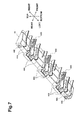
- FIG. 7 is a perspective view of an outer guide when viewed from an outer guiding portion
- FIG. 8 illustrates an operation procedure for removing an outer guiding portion
- FIG. 9 illustrates an operation procedure for removing an inner guiding portion
- FIG. 10 illustrates an operation procedure for removing a fixing unit
- FIG. 11 illustrates an operation procedure for removing the fixing unit
- FIG. 12 is a flowchart of attaching and removing the fixing unit.
- An image forming apparatus may be a multifunction apparatus 1 where a monochrome printer unit 3 and a flatbed-type scanner unit 5 are combined, as shown in FIG. 1 .
- the multifunction apparatus 1 may include the printer unit 3 , the scanner unit 5 disposed above the printer unit 3 , and a sheet ejection portion 7 provided between the printer unit 3 and the scanner unit 5 .
- a recording sheet (hereinafter referred to as a sheet), e.g., a plain, glossy, or transparency sheet, on which an image has been formed or printed in the printer portion, is ejected to the sheet ejection portion 7 .
- the printer unit 3 may be an electrophotographic image forming apparatus configured to form an image on a sheet by transferring a developer image onto the sheet.
- the scanner unit 5 may be a flatbed-type image reading apparatus configured to read an image on a document placed at rest.
- the printer unit 3 may include, in a housing 10 , an image forming section 20 , a feeder section 30 , and a conveyance unit 40 .
- the image forming section 20 may be configured to form an image on a sheet.
- the feeder portion 30 may be configured to supply a sheet to the image forming section 20 .
- the conveyance unit 40 constitutes a conveyance path L having generally a U-shape, through which a sheet on which an image has been completely formed at the image forming section 20 is conveyed toward an ejection opening 9 . By traveling the path, the sheet's orientation may be flipped, e.g., changed by approximately 180 degrees.
- An opening 12 may be provided on a rear side of the housing 10 and at a turn-around portion of the conveyance path L, which is a curved portion of the U-shape. Jammed sheets in the conveyance unit 40 or fixing unit 23 can be removed through the opening 12 .
- the opening 12 may be opened and closed by a rear cover 41 pivotally disposed on the rear side of the housing 10 .
- An ejection tray 11 may be disposed on an upper side of the housing 10 and above the fixing unit 23 .
- the ejection tray 11 may be configured to receive at least a sheet ejected from the ejection opening 9 thereon.
- the ejection tray 11 may be inclined with respect to a horizontal plane such that it is lower (e.g., closer to the fixing unit 23 ) at the ejection opening 9 .
- a lowermost end position 11 A of the ejection tray 11 is lower than an upper end position 23 D of the fixing unit 23 .
- the image forming unit 20 and the conveyance unit 40 may be attached to a frame (not shown), which may be a part of the apparatus body.
- the frame may include side frames (not shown) disposed on left and right sides of the housing 10 , a bottom frame (not shown) extending in a left-right direction to connect lower ends of the side frames, and a top frame (not shown) connecting upper ends of the side frames.
- the feeder section 30 may include a sheet supply tray 31 , a pickup roller 32 , a separation roller 33 , a separation pad 34 , a pair of conveying rollers 35 , and a pair of registration roller 36 .
- the sheet supply tray 20 may be disposed in a bottom portion in the housing 10 in a detachable manner.
- the pickup roller 32 , the separation roller 33 , and the separation pad 34 may be disposed above a front side of the sheet supply tray 31 .
- the pickup roller 32 may be configured to supply sheets toward the image forming unit 20 .
- the separation roller 33 , and the separation pad 34 may be configured to separate the sheets supplied by the pickup roller 32 one by one.
- the pair of conveying rollers 35 may be disposed downstream of the separation roller 33 with respect to a direction in which a sheet is conveyed (hereinafter referred to as a sheet conveyance direction), and may be configured to convey the sheet conveyed by the pickup roller 32 toward the image forming unit 20 .
- the pair of registration rollers 36 may be disposed downstream of the conveying rollers 35 and in front of an entrance to the image forming unit 20 .
- the registration rollers 36 may be configured to apply resistance to a sheet being conveyed to correct skewing.
- the image forming unit 20 may include a light exposure unit 21 , a developing unit 22 and the fixing unit 23 .
- the exposure unit 21 may be disposed in an upper portion in the housing 10 , and configured to form an electrostatic latent image on a surface of a photosensitive drum 22 A.
- the exposure unit 21 may mainly include a laser light source (not shown), a polygon mirror (not shown), f ⁇ lenses (not shown), and reflecting mirrors (not shown).
- the developing unit 22 may be stored below the light exposure unit 21 in the housing 10 in a detachable manner.
- the developing unit 22 may include a photosensitive drum 22 A, a charger 22 B, a developer storing portion 22 C, a supply roller 22 D, a developing roller 22 E, and a layer-thickness regulating blade 22 F.
- the photosensitive drum 22 A may be configured to carry thereon a developer to be transferred onto a sheet.
- the charger 22 B may be configured to charge the surface of the photosensitive drum 22 A.
- the developer storing portion 22 C may be configured to store a developer, e.g. toner.
- the supply roller 22 D and the developing roller 22 E may be disposed between the developer storing portion 22 C and the photosensitive drum 22 A, and configured to supply the developer from the developer storing portion 22 C to the photosensitive drum 22 A.
- the layer-thickness regulating blade 22 F may be configured to uniformly regulate the developer carried on the developing roller 22 E to a specified thickness as a thin layer.
- the developer in the developer storing portion 22 C may be supplied toward the developing roller 22 E by rotation of the supply roller 22 D, and carried on the developing roller 22 E.
- the developer carried on the developing roller 22 E may be supplied to the surface of the photosensitive drum 22 A, which may then be exposed to light by the light exposure unit 21 .
- a transfer roller 22 G may be disposed facing the photosensitive drum 22 A.
- the transfer roller 22 G may be given an electrical charge having a polarity (e.g., a negative electrical charge) opposite a polarity of an electrical charge applied to the photosensitive drum 22 A.
- a polarity e.g., a negative electrical charge
- the transfer roller 22 G rotates in synchronization with the photosensitive drum 22 A, the developer image carried on the surface of the photosensitive drum 22 A is transferred onto a print side of the sheet passing between the transfer roller 22 G and the photosensitive drum 22 A.
- the fixing unit 23 may be detachably attached to the frame (e.g., may be configured for easy removal).
- the fixing unit 23 may include a heat roller 23 A, a pressure roller 23 B, and a casing 23 C.
- the heat roller 23 A may be disposed to face the print side of a sheet and may be configured to apply heat to the developer image on the sheet.
- the pressure roller 23 B may be disposed facing the heat roller 23 A, and may be configured to press the sheet toward the heat roller 23 A.
- the heat roller 23 A and the pressure roller 23 B may be stored in the casing 23 C.
- the conveyance unit 40 may be disposed downstream of the fixing unit 23 in the sheet conveyance direction, and constitutes the conveyance path L from the fixing unit 23 to the ejection port 9 .
- a sheet ejected from the fixing unit 23 is conveyed to the ejection tray 11 through the conveyance path L.
- the conveyance unit 40 may be configured from the following elements.
- a pair of conveying rollers 42 A, 42 B may be configured to convey a sheet ejected from the fixing unit 23 while rotating in contact with the sheet.
- a lower conveying roller 42 A may be a drive roller configured to apply force to a sheet
- an upper conveying roller 42 B may be a driven roller configured to press the sheet toward the drive roller 42 A and be rotated by the sheet being conveyed.
- the drive rollers 42 A may be mounted around a shaft 42 C, and obtain power from an electric motor via a plurality of gears (not shown) to rotate.
- the driven rollers 42 B may be mounted to the apparatus body so as to move in a direction generally perpendicular to an axial direction of the shaft 42 C that drives the drive rollers 42 A.
- Each driven roller 42 B may be pressed toward its corresponding drive roller 42 A by an elastic member, e.g. a spring (not shown).
- a turning guide 43 may be disposed downstream of the conveying rollers 42 A, 42 B in the sheet conveyance direction.
- the turning guide 43 may be disposed in the turn-around portion of the conveyance path L, and configured to change the conveyance direction of the sheet passing between the conveying rollers 42 A, 42 B upward by approximately 180 degrees.
- the turning guide 43 may be pivotally mounted to a holding member 43 A to which the shaft 42 C of the drive rollers 42 A is mounted.
- the holding member 43 A is pivotally mounted to the frame. With this configuration, as the holding member 43 A pivots, the drive rollers 42 A shift towards, or away from, driven rollers 42 B.
- An outer guide 44 and an inner guide 45 may be disposed downstream of the turning guide 43 in the sheet conveyance direction, in other words, downstream of the turn-around portion of the conveyance path L.
- the outer guide 44 constitutes an outer guiding member in the conveyance path L and the inner guide 44 constitutes an inner guiding member in the conveyance path L.
- a pair of ejection rollers 46 A, 46 B may be disposed on the most downstream side of the conveyance path L, that is, in front of the ejection opening 9 .
- the ejection rollers 46 A, 46 B may be configured to cause the sheet to be ejected to the ejection tray 11 .
- An upper ejection roller 46 A may be configured to contact the print side of the sheet and apply force to the sheet, and a lower ejection roller 46 B may be configured to contact the lower side of the sheet, opposite the print side, and press the sheet toward the upper ejection roller 46 A, and can be rotated by the sheet being ejected.
- a rotation center 46 C of the upper ejection roller 46 A may be positioned further forward than a vertical phantom line L 1 that is tangent to an outer surface of the pressure roller 23 B.
- a leading end of the sheet ejected to the ejection tray 11 may be positioned toward the front side of the multifunction apparatus 1 .
- the inner guide 45 may be coupled to the lowermost end position 11 A of the ejection tray 11 , and may be configured to be attached to, and removed from, the ejection tray 11 that is a part of the housing 10 (See FIG. 10 , showing inner guide 45 removed).
- the inner guide 45 may be provided with inner guiding portions 45 A.
- the inner guide 45 may be inclined such that a distance between the inner and outer guides is smaller near the ejection opening than it is at the turnaround portion of the conveyance path L.
- the outer guide 44 may be attached to a top cover 13 forming a part of frame defining an upper end of the opening 12 in a detachable manner (e.g., so that it is easily removed).
- the outer guide 44 may be provided, close to the ejection roller 46 A, with an engaging portion 44 C, which may be stopped in an engaged state with a hook 13 A provided in the top cover 13 .
- Screws 44 B may be inserted into the outer guide 44 from the rear side toward the front side, and fixed to hold the outer guide 44 to the top cover 13 .
- the outer guide 44 When the screws 44 B are removed, the outer guide 44 may be moved horizontally toward the rear (toward the opening 12 ), so that the outer guide 44 can be easily removed from the top cover 13 .
- screw holes 44 E ( FIG. 7 ) for inserting the corresponding screws 44 B therein, and the engaging portion 44 C, may be disposed at least on a one-by-one basis on opposing sides of the outer guide 44 in a longitudinal direction (i.e., a left-right direction illustrated in FIG. 7 ).
- the top cover 13 may constitute a top wall portion of the housing 10 covering an upper surface of the outer guide 44 .
- the top cover 13 may also function as a joint member connecting the printer unit 3 and the scanner unit 5 .
- the outer guide 44 may be provided with outer guiding portions 44 A disposed facing the inner guide 45 .
- the outer guiding portions 44 A may extend in the front-to-rear direction (as shown in FIG. 7 ) from the opening 12 side toward the ejection rollers 46 A, 46 B, to guide a sheet toward the ejection rollers 46 A, 46 B.
- the outer guiding portions 44 A may protrude downward from the top cover 13 so as to cover the inner guide 45 from the rear. As shown in FIG. 7 , the outer guiding portions 44 A may be ribs protruding downward and extending from the rear toward the front and overlapping each other in the left-right direction.
- Lower ends of the outer guiding portions 44 A may be inclined relative to a horizontal direction such that their protruding dimension (H, in FIGS. 4 and 5 ) from the top cover 13 increases from the front side (e.g., the ejection rollers 46 A, 46 B) toward the rear (e.g., the opening 12 ).
- the protruding dimension (H) of each outer guiding portion 44 A may be measured with reference to a surface on which the outer guide 44 and the top cover 13 are attached to each other.
- the outer guide 44 may be positioned further toward the rear (e.g., closer to the opening 12 ) than the inner guide 45 is. When viewed from the rear side in FIG. 5 , the outer guide 44 overlaps at least part of the inner guide 45 . Thus, as illustrated in FIG. 5 , the outer guide 44 obstructs the removal of the inner guide 45 from the housing 10 .
- the outer guide 44 may first be removed from the housing 10 , and then the inner guide 45 may be removed, and then the fixing unit 23 can be removed from the housing 10 .
- the outer guide 44 includes a plurality of, e.g., eleven, outer guiding portions 44 A.
- POM Polyacetal
- the outer guiding portions 44 A may be integrally formed with the outer guide 44 , while the outer guiding portions 44 D may be manufactured separately from the outer guide 44 and then fixed to the outer guide 44 .
- the rear cover 41 may be removably and pivotally attached to the housing 10 , and may include a guide groove 41 A, which may be an elongated opening in which a guide pin (not shown) of the turning guide 43 may be slidably inserted.
- the turning guide 43 may be moved in connection with the rear cover 41 so that the turn-around portion of the conveyance path L is released.
- the outer guide 44 may first be removed, and then the inner guide 45 may be removed, with the fixing unit 23 being removed after the inner and outer guides 44 and 45 are removed.
- the rear cover 41 may be opened or removed from the housing 10 , the screws 44 B are unscrewed, and then the outer guide 44 is removed from the top cover 13 by moving the outer guide 44 toward the opening 12 as shown in a phantom line of FIG. 8 .
- the inner guide 45 may be removed from the ejection tray 11 by moving the inner guide 45 toward the opening 12 , and then the fixing unit 23 may be removed from the housing 10 by moving the fixing unit 23 toward the opening 12 as shown in a phantom line of FIG. 10 .
- the above removal procedure may be reversed. Specifically, the fixing unit 23 , the inner guide 45 , and the outer guide 44 may be sequentially installed in the housing 10 in this order, and then the rear cover 41 may be closed or attached to the housing 10 .
- the outer guide 44 may be attached to the top cover 13 in a detachable manner. After the outer guide 44 is removed from the housing 10 , the inner guide 45 can be easily removed from the housing 10 regardless of interference with the outer guide 44 . Thus, the workability of attaching and removing the inner guide 45 and the fixing unit 23 can be improved.
- the rotation center 46 C of the ejection roller 46 A configured to contact the upper surface of a sheet is positioned further forward than the phantom line L 1 , which increases the area where the inner guide 45 and the outer guide 44 face each other.
- the multifunction apparatus 1 may be applied to, but are not limited to, the multifunction apparatus 1 combining the printer unit 3 and the scanner unit 5 .
- the features may be applied to an image forming apparatus as a discrete apparatus such as a monochrome or color printer, or an image forming apparatus using LED as a light source of the exposure unit 21 .
- the outer guide 44 is attached to the top cover 13 .
- the outer guide 44 may be attached to any portion other than the top cover 13 , and may form a part of a frame defining the opening 12 therein.
- the inner guide 45 is attached to the housing 10 .
- this attachment may be made in a variety of ways.
- the inner guide 45 may be a separate unit that can be attached to or removed from the fixing unit 23 , or it may be integrally formed with the fixing unit 23 .
- the rear cover 41 may be opened or removed from the housing 10 (S 1 ).
- the outer guide 44 may be removed (S 2 ).
- the inner guide 45 may be removed (S 3 ).
- the fixing unit 23 may be removed (S 4 ).
- the above removal procedure may be reversed. Specifically, the fixing unit 23 may be attached to the housing 10 (S 5 ).
- the inner guide 45 may be attached to the housing 10 (S 6 ).
- the outer guide 44 may be attached to the housing 10 (S 7 ).
- the rear cover 41 may be closed or attached to the housing 10 (S 8 ).
Landscapes
- Physics & Mathematics (AREA)
- General Physics & Mathematics (AREA)
- Electrophotography Configuration And Component (AREA)
- Feeding Of Articles By Means Other Than Belts Or Rollers (AREA)
Abstract
Description
Claims (10)
Applications Claiming Priority (2)
| Application Number | Priority Date | Filing Date | Title |
|---|---|---|---|
| JP2007230411A JP4652384B2 (en) | 2007-09-05 | 2007-09-05 | Image forming apparatus |
| JP2007-230411 | 2007-09-05 |
Publications (2)
| Publication Number | Publication Date |
|---|---|
| US20090060573A1 US20090060573A1 (en) | 2009-03-05 |
| US8041254B2 true US8041254B2 (en) | 2011-10-18 |
Family
ID=40407741
Family Applications (1)
| Application Number | Title | Priority Date | Filing Date |
|---|---|---|---|
| US12/204,754 Expired - Fee Related US8041254B2 (en) | 2007-09-05 | 2008-09-04 | Image forming apparatus medium guide configuration and method |
Country Status (2)
| Country | Link |
|---|---|
| US (1) | US8041254B2 (en) |
| JP (1) | JP4652384B2 (en) |
Cited By (1)
| Publication number | Priority date | Publication date | Assignee | Title |
|---|---|---|---|---|
| US20130321882A1 (en) * | 2012-05-31 | 2013-12-05 | Kyocera Document Solutions Inc. | Image reading apparatus and image forming apparatus provided with same |
Families Citing this family (2)
| Publication number | Priority date | Publication date | Assignee | Title |
|---|---|---|---|---|
| JP6248752B2 (en) | 2014-03-28 | 2017-12-20 | ブラザー工業株式会社 | Image forming apparatus |
| JP7501204B2 (en) | 2020-07-29 | 2024-06-18 | ブラザー工業株式会社 | Image forming device |
Citations (5)
| Publication number | Priority date | Publication date | Assignee | Title |
|---|---|---|---|---|
| US20060008294A1 (en) * | 2004-07-12 | 2006-01-12 | Brother Kogyo Kabushiki Kaisha | Image forming device and fixing unit |
| JP2006053508A (en) | 2004-07-12 | 2006-02-23 | Brother Ind Ltd | Image forming apparatus and fixing unit |
| US20060083542A1 (en) * | 2004-10-20 | 2006-04-20 | Brother Kogyo Kabushiki Kaisha | Image-forming device |
| JP2006335489A (en) | 2005-05-31 | 2006-12-14 | Brother Ind Ltd | Image forming apparatus |
| JP2007017488A (en) | 2005-07-05 | 2007-01-25 | Brother Ind Ltd | Image forming apparatus |
-
2007
- 2007-09-05 JP JP2007230411A patent/JP4652384B2/en not_active Expired - Fee Related
-
2008
- 2008-09-04 US US12/204,754 patent/US8041254B2/en not_active Expired - Fee Related
Patent Citations (8)
| Publication number | Priority date | Publication date | Assignee | Title |
|---|---|---|---|---|
| US20060008294A1 (en) * | 2004-07-12 | 2006-01-12 | Brother Kogyo Kabushiki Kaisha | Image forming device and fixing unit |
| JP2006053508A (en) | 2004-07-12 | 2006-02-23 | Brother Ind Ltd | Image forming apparatus and fixing unit |
| US20090022515A1 (en) | 2004-07-12 | 2009-01-22 | Brother Kogyo Kabushiki Kaisha | Image Forming Device and Fixing Unit |
| US7555239B2 (en) | 2004-07-12 | 2009-06-30 | Brother Kogyo Kabushiki Kaisha | Image forming device and fixing unit |
| US20060083542A1 (en) * | 2004-10-20 | 2006-04-20 | Brother Kogyo Kabushiki Kaisha | Image-forming device |
| JP2006335489A (en) | 2005-05-31 | 2006-12-14 | Brother Ind Ltd | Image forming apparatus |
| US20070001368A1 (en) | 2005-05-31 | 2007-01-04 | Brother Kogyo Kabushiki Kaisha | Image forming apparatus |
| JP2007017488A (en) | 2005-07-05 | 2007-01-25 | Brother Ind Ltd | Image forming apparatus |
Non-Patent Citations (2)
| Title |
|---|
| JP Notice of Reasons for Rejection, Appeal No. Appeal 2010-005154, Appln. No. 2007-230411, mail date Nov. 9, 2010 (original JP language and translation of claims and reasons of rejection). |
| JP Office Action, Appln. No. 2007-230411, mail date Aug. 18, 2009. |
Cited By (2)
| Publication number | Priority date | Publication date | Assignee | Title |
|---|---|---|---|---|
| US20130321882A1 (en) * | 2012-05-31 | 2013-12-05 | Kyocera Document Solutions Inc. | Image reading apparatus and image forming apparatus provided with same |
| US8837020B2 (en) * | 2012-05-31 | 2014-09-16 | Kyocera Document Solutions Inc. | Image reading apparatus and image forming apparatus provided with same |
Also Published As
| Publication number | Publication date |
|---|---|
| US20090060573A1 (en) | 2009-03-05 |
| JP2009063749A (en) | 2009-03-26 |
| JP4652384B2 (en) | 2011-03-16 |
Similar Documents
| Publication | Publication Date | Title |
|---|---|---|
| CN2893753Y (en) | Recording medium transfer device, image forming apparatus and cartridge | |
| US7929881B2 (en) | Process cartridge and electrophotographic image forming apparatus | |
| US7606512B2 (en) | Image forming device with cover protrusions | |
| US9340378B2 (en) | Image forming apparatus | |
| US8160487B2 (en) | Image-forming device having first and second sheet guide pairs for guiding sheets of different sizes | |
| EP2624059B1 (en) | Image forming apparatus | |
| US8340565B2 (en) | Image forming device having detachable drum unit | |
| US8041254B2 (en) | Image forming apparatus medium guide configuration and method | |
| US7463848B2 (en) | Image forming apparatus having a state in which a conveying roller is pressed toward a recording medium | |
| JP5549543B2 (en) | Image forming apparatus | |
| US8081902B2 (en) | Image-forming device with detachable belt unit | |
| JP4569646B2 (en) | Image forming apparatus | |
| US8280288B2 (en) | Image forming device having protection member for protecting peeling claw | |
| JP5291027B2 (en) | Sheet material feeding apparatus and image forming apparatus | |
| JP4568354B2 (en) | Sheet transport device | |
| JP2006030418A (en) | Image forming apparatus | |
| JP5591572B2 (en) | Medium conveying apparatus and image forming apparatus | |
| US9141022B2 (en) | Image forming apparatus having an image forming unit arranged detachably to an apparatus body and having an image carrier, an exposure device, arranged in the apparatus body, for exposing the image carrier, and a cleaner for cleaning the exposure device | |
| US8306458B2 (en) | Image forming device including regulation member that regulates movement of flapper when rear cover is open | |
| US7583921B2 (en) | Image forming apparatus and transfer unit | |
| JP7432108B2 (en) | image forming device | |
| US20050070386A1 (en) | Belt device and image forming apparatus | |
| JP5625090B2 (en) | Sheet material feeding apparatus and image forming apparatus | |
| JP2009210902A (en) | Image forming apparatus | |
| JP2022048496A (en) | Image forming device |
Legal Events
| Date | Code | Title | Description |
|---|---|---|---|
| AS | Assignment |
Owner name: BROTHER KOGYO KABUSHIKI KAISHA, JAPAN Free format text: ASSIGNMENT OF ASSIGNORS INTEREST;ASSIGNOR:ITO, SAKAE;REEL/FRAME:021487/0697 Effective date: 20080903 |
|
| ZAAA | Notice of allowance and fees due |
Free format text: ORIGINAL CODE: NOA |
|
| ZAAB | Notice of allowance mailed |
Free format text: ORIGINAL CODE: MN/=. |
|
| STCF | Information on status: patent grant |
Free format text: PATENTED CASE |
|
| FPAY | Fee payment |
Year of fee payment: 4 |
|
| MAFP | Maintenance fee payment |
Free format text: PAYMENT OF MAINTENANCE FEE, 8TH YEAR, LARGE ENTITY (ORIGINAL EVENT CODE: M1552); ENTITY STATUS OF PATENT OWNER: LARGE ENTITY Year of fee payment: 8 |
|
| FEPP | Fee payment procedure |
Free format text: MAINTENANCE FEE REMINDER MAILED (ORIGINAL EVENT CODE: REM.); ENTITY STATUS OF PATENT OWNER: LARGE ENTITY |
|
| LAPS | Lapse for failure to pay maintenance fees |
Free format text: PATENT EXPIRED FOR FAILURE TO PAY MAINTENANCE FEES (ORIGINAL EVENT CODE: EXP.); ENTITY STATUS OF PATENT OWNER: LARGE ENTITY |
|
| STCH | Information on status: patent discontinuation |
Free format text: PATENT EXPIRED DUE TO NONPAYMENT OF MAINTENANCE FEES UNDER 37 CFR 1.362 |
|
| FP | Lapsed due to failure to pay maintenance fee |
Effective date: 20231018 |