US8033177B2 - MEMS pressure sensor and housing therefor - Google Patents
MEMS pressure sensor and housing therefor Download PDFInfo
- Publication number
- US8033177B2 US8033177B2 US12/367,689 US36768909A US8033177B2 US 8033177 B2 US8033177 B2 US 8033177B2 US 36768909 A US36768909 A US 36768909A US 8033177 B2 US8033177 B2 US 8033177B2
- Authority
- US
- United States
- Prior art keywords
- diaphragm
- fluid
- housing
- mems
- pressure sensor
- Prior art date
- Legal status (The legal status is an assumption and is not a legal conclusion. Google has not performed a legal analysis and makes no representation as to the accuracy of the status listed.)
- Active, expires
Links
Images


Classifications
-
- G—PHYSICS
- G01—MEASURING; TESTING
- G01L—MEASURING FORCE, STRESS, TORQUE, WORK, MECHANICAL POWER, MECHANICAL EFFICIENCY, OR FLUID PRESSURE
- G01L19/00—Details of, or accessories for, apparatus for measuring steady or quasi-steady pressure of a fluent medium insofar as such details or accessories are not special to particular types of pressure gauges
- G01L19/0061—Electrical connection means
- G01L19/0084—Electrical connection means to the outside of the housing
-
- G—PHYSICS
- G01—MEASURING; TESTING
- G01L—MEASURING FORCE, STRESS, TORQUE, WORK, MECHANICAL POWER, MECHANICAL EFFICIENCY, OR FLUID PRESSURE
- G01L19/00—Details of, or accessories for, apparatus for measuring steady or quasi-steady pressure of a fluent medium insofar as such details or accessories are not special to particular types of pressure gauges
- G01L19/06—Means for preventing overload or deleterious influence of the measured medium on the measuring device or vice versa
- G01L19/0627—Protection against aggressive medium in general
- G01L19/0645—Protection against aggressive medium in general using isolation membranes, specially adapted for protection
-
- G—PHYSICS
- G01—MEASURING; TESTING
- G01L—MEASURING FORCE, STRESS, TORQUE, WORK, MECHANICAL POWER, MECHANICAL EFFICIENCY, OR FLUID PRESSURE
- G01L9/00—Measuring steady of quasi-steady pressure of fluid or fluent solid material by electric or magnetic pressure-sensitive elements; Transmitting or indicating the displacement of mechanical pressure-sensitive elements, used to measure the steady or quasi-steady pressure of a fluid or fluent solid material, by electric or magnetic means
- G01L9/0041—Transmitting or indicating the displacement of flexible diaphragms
- G01L9/0072—Transmitting or indicating the displacement of flexible diaphragms using variations in capacitance
- G01L9/0073—Transmitting or indicating the displacement of flexible diaphragms using variations in capacitance using a semiconductive diaphragm
Definitions
- the present invention is directed generally to pressure sensors.
- MEMS pressure sensor dies typically have a MEMS diaphragm fabricated to be integrated in the MEMS die and are typically positioned to directly contact the fluid being measured. In some situations, a MEMS diaphragm may not be compatible with the particular environment and/or the fluid being measured. In other cases the MEMS pressure sensor die may be part of other components sharing a common package. These situations can reduce the desirability of the MEMS diaphragm directly contacting the fluid being measured.
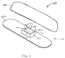
- FIG. 1 is a perspective view of a pressure sensing system with the cover removed.
- FIG. 2 is an exploded side elevational view of the pressure sensing system of FIG. 1 .
- FIG. 3 is an enlarged top plan view of the pressure sensing system of FIG. 1 without the cover.
- FIG. 4 is a cross-sectional view of the pressure sensing system taken substantially along line 4 - 4 of FIG. 3 .
- FIG. 5 is a top plan view of a MEMS pressure sensing die of the pressure sensing system of FIG. 1 .
- FIG. 6 is a top plan view of a sensor containment cover of the pressure sensing system of FIG. 1 .
- FIG. 7 is a cross-sectional view of the sensor containment cover taken substantially along line 7 - 7 of FIG. 6 .
- a pressure sensing system is used to position a MEMS diaphragm of a MEMS pressure sensor die in a housing to indirectly sample pressure state of a fluid being measured.
- a second housing diaphragm is used to make direct contact with the fluid being measured.
- Pressure state of the fluid being measured is transferred from the housing diaphragm in direct contact through an electrically insulating intermediary fluid to the MEMS diaphragm thereby allowing the MEMS pressure sensor die to indirectly sample pressure state of the fluid being measured.
- Electrically conductive support members and electrically conductive solid vias are used to electrically couple circuitry outside the housing.
- FIG. 1 An exemplary pressure sensing system 100 is depicted in FIG. 1 as having a pressure sensing assembly 102 enclosed by a component package 103 having a package base 104 and a cover 106 shaped to sealably coupled with the package base.
- the package base 104 can be made from a substrate material.
- the pressure sensing assembly 102 is integrally jointed with the package base 104 with a portion of the package base serving as a wall for the pressure sensing assembly 102 .
- the pressure sensing assembly 102 includes a housing 107 with a housing cover 108 having an exterior surface 108 a , an interior surface 108 b , and conductive solid vias 110 extending therebetween (better shown in FIG. 4 ).
- the housing 107 can be formed from ceramic and attached to the package base 104 with epoxy, silicone, brazing, or other attachment means. Alternatively, the housing 107 can be formed from metal and attached to the package base 104 with epoxy, silicone, brazing, laser welding, or other attachment means. As depicted, the housing cover 108 can be a hybrid printed circuit board formed from glass, ceramic, or other mechanically stable material compatible with technology involving printed circuitry. The housing cover 108 can be sealed to the housing 107 such as with epoxy, silicone, or braze. The housing 107 also includes a plug hole 112 sized to receive a plug 114 .
- the pressure sensing assembly 102 further includes a MEMS pressure sensor die 116 that is in electrical contact with electrically conductive support members 118 , which in turn are in electrical contact with the electrically conductive solid vias 110 further discussed below.
- the MEMS pressure sensor die 116 can be designed to determine fluid pressure levels either through capacitive or piezoresistive means.
- the conductive support members 118 also mechanically couple the MEMS pressure sensor die 116 to the housing cover 108 . In some implementations, portions of solder, such as solder bumps, are used for the conductive support members 118 . Also shown in FIG.
- a housing diaphragm 120 that is positioned to seal a housing aperture 121 shown in cross-section in FIG. 4 , in that portion of the package base 104 that serves as a wall of the pressure sensing assembly.
- the housing diaphragm 120 can be attached to the package base 104 by laser welding, epoxy, silicone, electrochemical bonding, electrochemical forming, brazing or other means.
- the housing diaphragm 120 has an exterior surface 120 a to contact a fluid being measured that has a pressure value that is desired to be known and an oppositely facing interior surface 120 b.
- FIG. 4 a cross-sectional view of the pressure sensing assembly 102 is found in FIG. 4 showing the package base 104 to have a plug aperture 122 communicating with the plug hole 112 .
- the MEMS pressure sensor die 116 has a MEMS diaphragm 123 in communication with a chamber 124 defined in part by the package base 104 , the housing 107 , and the housing cover 108 .
- the chamber 124 contains an intermediary fluid 125 , which is used to transfer pressure applied to the exterior surface 120 a of the housing diaphragm 120 to the MEMS diaphragm 123 .
- a fill port 126 is also in communication with the chamber 124 when the plug 114 is removed from the plug hole 112 to fill the chamber with the intermediary fluid 12 .
- the fill port 126 can be machined in the housing 107 and provides access to the chamber 124 .
- the plug hole 112 can be drilled in the housing 107 to receive the plug 114 , which is used to seal the fill port 126 and the chamber 124 after the chamber has been filled with the intermediary fluid.
- the plug 114 can be made as a stop cork or other device to seal the fill port 126 and the chamber 124 as long as the volume of the sealed chamber has the same value each time the chamber is sealed.
- the MEMS pressure sensor die 116 is shown in FIG. 5 to include electrical circuitry contacts 128 used for electrical communication with the MEMS pressure sensor die, such as to output pressure values or status information from the MEMS pressure sensor die or to input control signals to the MEMS pressure sensor die.
- the circuitry contacts 128 of the MEMS pressure sensor die 116 are aligned with the conductive solid vias 110 in the housing cover 108 , better shown in FIGS. 6 and 7 , to conduct the electrical communication with the MEMS pressure sensor die outside of the housing 107 .
- the conductive solid core vias 110 of the housing cover 108 act as sealed electrical feedthrough interconnects between the exterior surface 108 a and the interior surface 108 b , which is electrically coupled to the electrical circuitry contacts 128 of the MEMS pressure sensor die 116 through the conductive support members 118 .
- External wires 130 are attached to the external surface 108 a of the conductive vias 110 with solder, wire bond, conductive epoxy or other electrical bonding method.
- the chamber 124 is filled with an intermediary fluid that is electrically insulating, such as a silicone based fluid such as silicone oil or other insulator based fluid.
- an intermediary fluid that is electrically insulating, such as a silicone based fluid such as silicone oil or other insulator based fluid.
- the chamber 124 can be vacuum filled with silicone oil by immersing the entire pressure sensing assembly 102 in the silicone oil, placing the immersed pressure sensing assembly in a vacuum, and then drawing the air out of the chamber 124 .
- the plug 114 can then be inserted into the plug hole 112 to seal off the chamber 124 .
- an additional plug hole 112 and an additional fill port 126 can be used as a vent to introduce pressurized silicone oil or other pressurized fluid in the chamber 124 . After filling the chamber 124 , all of the plug holes 112 each would be sealed with one of the plugs 114 .
- External fluid pressure impinging upon the exterior surface 120 a of the housing diaphragm 120 sealing the housing aperture 121 of the package base 104 is transferred to the intermediary fluid in the chamber 124 through the housing diaphragm whereby the MEMS diaphragm is affected and the MEMS pressure sensor die senses a pressure level corresponding to the external fluid pressure.
- the sensor has an external diaphragm in contact with an test environment in which a measurement of the pressure of the test environment is desired.
- the sensor also has a MEMS device that translates pressure into something like a voltage to be measured.
- An incompressible internal fluid such as an oil is positioned between the diaphragm and the MEMS.
- the invention consists of methods to decrease the errors in pressure sensors due to thermal expansion differences between sensor components.
- a typical method for constructing a pressure sensor for use in corrosive or harsh environments utilizes a small sensing element such as a piezoresistive or capacitive micro-machined electromechanical (MEMS) die sealed into a larger housing containing an electrically insulating isolation fluid such as a silicone oil or other type of synthetic oil such as a hydraulic fluid.
- This housing is constructed with an isolation diaphragm or membrane to transmit pressure from the external environment, through the minimally compressible isolation fluid, to the sensing element.
- the isolation diaphragm must move freely over the operating pressure range and also over the operating temperature range so that it does not introduce a significant pressure differential, which would result in an error in the pressure reading.
- the diaphragm material must be maintained in a linear, elastic region, as opposed to a plastic region, as it is deformed, so that its behavior does not change over temperature and pressure cycles, altering the calibration of the sensor.
- the isolation fluid expands volumetrically with increasing temperature at a rate higher than the housing, resulting in an outward pressure on the diaphragm.
- the amount of fluid expansion is characterized by the coefficient of thermal expansion (CTE) for the fluid.
- CTE coefficient of thermal expansion
- the isolation diaphragm is typically constructed with a large area compared to the volume of the contained fluid, minimizing the deflection of the diaphragm and thereby minimizing the amount of strain within the diaphragm material.
- bellows or corrugated diaphragms are used on industrial sensors to allow the isolation diaphragm to move over a larger distance while keeping the diaphragm materials in a linear, purely elastic range and minimizing the developed differential pressure across the diaphragm. This in turn allows high operating and manufacturing temperatures without plastically deforming the isolation diaphragm.
- this technique does not scale well when the pressure sensor is miniaturized for uses in small transducer applications, for example when the pressure sensor is intended for implantation into the human body, or in industrial applications where it is often desirable to miniaturize the sensor. In these cases, the isolation diaphragm area becomes small compared to the volume of contained fluid.
- the temperature is then limited to below around 60° C.
- Many fabrication processes involve higher temperatures, such as the elevated temperature required to fully cure epoxy or other thermosets.
- standard methods for sterilizing medical devices also utilize process temperatures, exceeding 60° C.
- One method to mitigate this effect utilizes a zero-CTE fluid and is reportedly in development by Kavlico.
- the first category includes the concept under development by Kavlico, but also includes methods to keep the fluid cooler than the environment.
- a tiny heat-transfer device such as a Peltier cooler could be included to keep the local temperature (ie, the fluid) constant and keep the fluid from expanding.
- a Peltier cooler can either heat or cool, depending upon the direction of current flow, so it could provide a constant-temperature environment for the sensor in either high or low ambient temperature conditions.
- An active control loop, with a temperature sensor in the fluid, could maintain constant temperature.
- the second category utilizes a volume of negative CTE material (U.S. Pat. No. 6,066,585).
- This material could be implemented as either a powder scattered around in the fluid, as a 3D volumetric block, or as a coating on the walls of the housing.
- the CTE of the material and the amount of the material could be balanced with the fluid CTE to provide minimal or zero net volume expansion with temperature.
- An additional implementation could be a small block of piezoceramic (such as lead zirconate titanate, or PZT) or another material that is in an expanded state during the filling process.
- the material could be released back to its unexpanded state leaving a negative displacement on the diaphragm.
- the material could be mounted to the walls of the chamber.
- a temperature sensor in the fluid could be used to drive a control loop that would provide an output voltage to the piezoceramic element.
- the third category includes several mechanical or electromechanical methods for increasing the chamber volume to match the expanding fluid volume.
- One method employs a bilaminar diaphragm composed of two materials with different thermal expansion coefficients (like a thermostat element). The diaphragm would expand outward as the temperature increased.
- the expansion can also be activated with electromechancial force (ie, a piezoelectric bender element (unimorph or bimorph) or a NiTi (Nitinol) shape memory element).
- electromechancial force ie, a piezoelectric bender element (unimorph or bimorph) or a NiTi (Nitinol) shape memory element.
- This method could also be implemented by an arm or other micro-actuator attached to the diaphragm.
- a temperature sensor in the fluid could be used to drive a control loop that would provide an output voltage or current to control the active element.
- a first method could use a housing material with a higher CTE to expand with increasing temperature.
- a second method could use a NiTi or piezoelectric washer (i.e., an annular structure that is integral to the housing) placed in the wall of the housing expanding the overall height.
- a control signal would likely be required to expand the housing when the temperature rises.
- Yet another method might also be to use a bistable state diaphragm (like an oil can bottom). During filling the diaphragm could minimize the volume of the fluid, and could be pulled or snapped into a position that minimizes the volume when exposed to higher temperatures. The diaphragm could then be pushed back into its original state after exposure to the high fabrication process temperature. This could also be implemented with a plug or bellows rather than a diaphragm.
Abstract
Description
-
- a. keep cool (Peltier device)
- b. zero-CTE fluid (ref Kavlico conversation)
-
- a. Negative CTE material in volume (block, powder)
- b. Piezoelectric (fill with the PZT material expanded, then contract leaving negative displacement on diaphragm)
-
- a. Dual CTE bi-laminar diaphragm
- b. Thermally activated (CTE) expanding housing
- c. Electromechanically activated expanding housing (NiTi, PZT)
- d. Mechanical
- i. Bi-stable state mechanical diaphragm
- ii. Bellows
- 1) Minimize the fluid expansion with increasing environmental temperature
- 2) Enclose a separate material that decreases volume when the temperature increases, for instance with a material with a negative thermal expansion coefficient
- 3) Design the sensor housing to expand in volume with increasing temperature
Claims (5)
Priority Applications (1)
| Application Number | Priority Date | Filing Date | Title |
|---|---|---|---|
| US12/367,689 US8033177B2 (en) | 2008-02-15 | 2009-02-09 | MEMS pressure sensor and housing therefor |
Applications Claiming Priority (2)
| Application Number | Priority Date | Filing Date | Title |
|---|---|---|---|
| US2921108P | 2008-02-15 | 2008-02-15 | |
| US12/367,689 US8033177B2 (en) | 2008-02-15 | 2009-02-09 | MEMS pressure sensor and housing therefor |
Publications (2)
| Publication Number | Publication Date |
|---|---|
| US20090205432A1 US20090205432A1 (en) | 2009-08-20 |
| US8033177B2 true US8033177B2 (en) | 2011-10-11 |
Family
ID=40953870
Family Applications (1)
| Application Number | Title | Priority Date | Filing Date |
|---|---|---|---|
| US12/367,689 Active 2030-01-30 US8033177B2 (en) | 2008-02-15 | 2009-02-09 | MEMS pressure sensor and housing therefor |
Country Status (1)
| Country | Link |
|---|---|
| US (1) | US8033177B2 (en) |
Cited By (5)
| Publication number | Priority date | Publication date | Assignee | Title |
|---|---|---|---|---|
| US20090068795A1 (en) * | 2002-12-27 | 2009-03-12 | Shinko Electric Industries Co., Ltd. | Production methods of electronic devices |
| US20120022562A1 (en) * | 2010-07-23 | 2012-01-26 | Boston Scientific Scimed, Inc. | Device to detect internal bleeding |
| US20180058955A1 (en) * | 2016-08-30 | 2018-03-01 | Honeywell International Inc. | Overforce control through sense die design |
| USD816049S1 (en) * | 2016-03-31 | 2018-04-24 | Lg Innotek Co., Ltd. | Sensor housing |
| US11649717B2 (en) | 2018-09-17 | 2023-05-16 | Saudi Arabian Oil Company | Systems and methods for sensing downhole cement sheath parameters |
Families Citing this family (4)
| Publication number | Priority date | Publication date | Assignee | Title |
|---|---|---|---|---|
| US20110004076A1 (en) * | 2008-02-01 | 2011-01-06 | Smith & Nephew, Inc. | System and method for communicating with an implant |
| US8975107B2 (en) | 2011-06-16 | 2015-03-10 | Infineon Techologies Ag | Method of manufacturing a semiconductor device comprising a membrane over a substrate by forming a plurality of features using local oxidation regions |
| US20130054159A1 (en) | 2011-08-31 | 2013-02-28 | E. Strode Pennebaker | Wireless tank level monitoring system |
| US11177514B2 (en) * | 2019-04-16 | 2021-11-16 | Xing Power Inc. | Battery system with management module |
Citations (4)
| Publication number | Priority date | Publication date | Assignee | Title |
|---|---|---|---|---|
| US6869818B2 (en) * | 2002-11-18 | 2005-03-22 | Redwood Microsystems, Inc. | Method for producing and testing a corrosion-resistant channel in a silicon device |
| US7004034B2 (en) * | 2002-04-10 | 2006-02-28 | Hewlett-Packard Development Company, L.P. | Pressure sensor and method of making the same having membranes forming a capacitor |
| US7011288B1 (en) * | 2001-12-05 | 2006-03-14 | Microstar Technologies Llc | Microelectromechanical device with perpendicular motion |
| US7162926B1 (en) * | 2005-08-04 | 2007-01-16 | Kavlico Corporation | Lead embedded pressure sensor |
-
2009
- 2009-02-09 US US12/367,689 patent/US8033177B2/en active Active
Patent Citations (5)
| Publication number | Priority date | Publication date | Assignee | Title |
|---|---|---|---|---|
| US7011288B1 (en) * | 2001-12-05 | 2006-03-14 | Microstar Technologies Llc | Microelectromechanical device with perpendicular motion |
| US7004034B2 (en) * | 2002-04-10 | 2006-02-28 | Hewlett-Packard Development Company, L.P. | Pressure sensor and method of making the same having membranes forming a capacitor |
| US6869818B2 (en) * | 2002-11-18 | 2005-03-22 | Redwood Microsystems, Inc. | Method for producing and testing a corrosion-resistant channel in a silicon device |
| US7125739B2 (en) * | 2002-11-18 | 2006-10-24 | Harris James M | Method for producing and testing a corrosion-resistant channel in a silicon device |
| US7162926B1 (en) * | 2005-08-04 | 2007-01-16 | Kavlico Corporation | Lead embedded pressure sensor |
Cited By (7)
| Publication number | Priority date | Publication date | Assignee | Title |
|---|---|---|---|---|
| US20090068795A1 (en) * | 2002-12-27 | 2009-03-12 | Shinko Electric Industries Co., Ltd. | Production methods of electronic devices |
| US8216884B2 (en) * | 2002-12-27 | 2012-07-10 | Shinko Electric Industries Co., Ltd. | Production methods of electronic devices |
| US20120022562A1 (en) * | 2010-07-23 | 2012-01-26 | Boston Scientific Scimed, Inc. | Device to detect internal bleeding |
| USD816049S1 (en) * | 2016-03-31 | 2018-04-24 | Lg Innotek Co., Ltd. | Sensor housing |
| US20180058955A1 (en) * | 2016-08-30 | 2018-03-01 | Honeywell International Inc. | Overforce control through sense die design |
| US10571348B2 (en) * | 2016-08-30 | 2020-02-25 | Honeywell International Inc. | Overforce control through sense die design |
| US11649717B2 (en) | 2018-09-17 | 2023-05-16 | Saudi Arabian Oil Company | Systems and methods for sensing downhole cement sheath parameters |
Also Published As
| Publication number | Publication date |
|---|---|
| US20090205432A1 (en) | 2009-08-20 |
Similar Documents
| Publication | Publication Date | Title |
|---|---|---|
| US8033177B2 (en) | MEMS pressure sensor and housing therefor | |
| US7305890B2 (en) | Micro-electromechanical sensor | |
| JP4860043B2 (en) | Error sensor, pressure transmitter and error compensation method for differential pressure measurement | |
| CN107445133B (en) | Compact load cell device with low sensitivity to thermo-mechanical package stress | |
| US8806964B2 (en) | Force sensor | |
| US7568394B1 (en) | Enhanced diaphragm for pressure sensing system and method | |
| US9182308B2 (en) | Leadless oil filled pressure transducer | |
| US8142362B2 (en) | Enhanced pressure sensing system and method | |
| US20030150275A1 (en) | Isolation technique for pressure sensing structure | |
| JP6659834B2 (en) | Pressure transmitter with overpressure protection | |
| WO2000045143A1 (en) | Media compatible packages for pressure sensing devices | |
| KR20030003256A (en) | Pressure sensor module | |
| JP5547894B2 (en) | Pressure sensor with flexible diaphragm | |
| RU2740125C1 (en) | Pressure sensor assembly | |
| JP6748788B2 (en) | Pneumatic base tactile sensor | |
| CN104006914A (en) | Systems and methods for a pressure sensor having a two layer die structure | |
| US20190242772A1 (en) | Mems pressure sensor with multiple sensitivity and small dimensions | |
| US6577224B2 (en) | Ultra high pressure transducers | |
| US6591686B1 (en) | Oil filled pressure transducer | |
| JP6807486B2 (en) | Pressure sensor configuration and its manufacturing method | |
| US20150027224A1 (en) | Micromechanical Measuring Element and Method for Producing a Micromechanical Measuring Element | |
| EP3260831B1 (en) | Low cost small force sensor | |
| KR20060004773A (en) | Micro accelerometer | |
| US20200232865A1 (en) | Pressure sensor system, measuring device and method for the manufacture thereof | |
| CN112985682A (en) | Differential pressure measurer |
Legal Events
| Date | Code | Title | Description |
|---|---|---|---|
| AS | Assignment |
Owner name: CARDIOMETRIX, INC., WASHINGTON Free format text: ASSIGNMENT OF ASSIGNORS INTEREST;ASSIGNORS:KEILMAN, GEORGE W.;JOHNSON, TIM;REEL/FRAME:022625/0942 Effective date: 20090424 |
|
| AS | Assignment |
Owner name: PACESETTER, INC.,CALIFORNIA Free format text: ASSIGNMENT OF ASSIGNORS INTEREST;ASSIGNOR:CARDIOMETRIX, INC.;REEL/FRAME:024054/0083 Effective date: 20100112 Owner name: PACESETTER, INC., CALIFORNIA Free format text: ASSIGNMENT OF ASSIGNORS INTEREST;ASSIGNOR:CARDIOMETRIX, INC.;REEL/FRAME:024054/0083 Effective date: 20100112 |
|
| STCF | Information on status: patent grant |
Free format text: PATENTED CASE |
|
| FPAY | Fee payment |
Year of fee payment: 4 |
|
| FEPP | Fee payment procedure |
Free format text: MAINTENANCE FEE REMINDER MAILED (ORIGINAL EVENT CODE: REM.); ENTITY STATUS OF PATENT OWNER: SMALL ENTITY |
|
| FEPP | Fee payment procedure |
Free format text: ENTITY STATUS SET TO UNDISCOUNTED (ORIGINAL EVENT CODE: BIG.); ENTITY STATUS OF PATENT OWNER: LARGE ENTITY |
|
| FEPP | Fee payment procedure |
Free format text: 7.5 YR SURCHARGE - LATE PMT W/IN 6 MO, LARGE ENTITY (ORIGINAL EVENT CODE: M1555); ENTITY STATUS OF PATENT OWNER: LARGE ENTITY |
|
| MAFP | Maintenance fee payment |
Free format text: PAYMENT OF MAINTENANCE FEE, 8TH YEAR, LARGE ENTITY (ORIGINAL EVENT CODE: M1552); ENTITY STATUS OF PATENT OWNER: LARGE ENTITY Year of fee payment: 8 |
|
| MAFP | Maintenance fee payment |
Free format text: PAYMENT OF MAINTENANCE FEE, 12TH YEAR, LARGE ENTITY (ORIGINAL EVENT CODE: M1553); ENTITY STATUS OF PATENT OWNER: LARGE ENTITY Year of fee payment: 12 |