US8025383B2 - Fluidically damped printhead - Google Patents

Fluidically damped printhead Download PDF

Info

Publication number
US8025383B2
US8025383B2 US11/688,863 US68886307A US8025383B2 US 8025383 B2 US8025383 B2 US 8025383B2 US 68886307 A US68886307 A US 68886307A US 8025383 B2 US8025383 B2 US 8025383B2
Authority
US
United States
Prior art keywords
ink
printhead
cartridge
conduit
support structure
Prior art date
Legal status (The legal status is an assumption and is not a legal conclusion. Google has not performed a legal analysis and makes no representation as to the accuracy of the status listed.)
Active, expires
Application number
US11/688,863
Other versions
US20070206056A1 (en
Inventor
Brian Robert Brown
Norman Micheal Berry
Garry Raymond Jackson
Paul Timothy Sharp
John Douglas Peter Morgan
Kia Silverbrook
Akira Nakazawa
Michael John Hudson
Christopher Hibbard
Samuel George Mallinson
Paul Justin Reichl
Current Assignee (The listed assignees may be inaccurate. Google has not performed a legal analysis and makes no representation or warranty as to the accuracy of the list.)
Memjet Technology Ltd
Original Assignee
Silverbrook Research Pty Ltd
Priority date (The priority date is an assumption and is not a legal conclusion. Google has not performed a legal analysis and makes no representation as to the accuracy of the date listed.)
Filing date
Publication date
Priority claimed from AU2006901084A external-priority patent/AU2006901084A0/en
Priority claimed from AU2006201083A external-priority patent/AU2006201083B2/en
Assigned to SILVERBROOK RESEARCH PTY LTD reassignment SILVERBROOK RESEARCH PTY LTD ASSIGNMENT OF ASSIGNORS INTEREST (SEE DOCUMENT FOR DETAILS). Assignors: BERRY, NORMAN MICHEAL, BROWN, BRIAN ROBERT, HIBBARD, CHRISTOPHER, HUDSON, MICHAEL JOHN, JACKSON, GARRY RAYMOND, MALLINSON, SAMUEL GEORGE, MORGAN, JOHN DOUGLAS PETER, NAKAZAWA, AKIRA, REICHL, PAUL JUSTIN, SHARP, PAUL TIMOTHY, SILVERBROOK, KIA
Priority to US11/688,863 priority Critical patent/US8025383B2/en
Application filed by Silverbrook Research Pty Ltd filed Critical Silverbrook Research Pty Ltd
Priority to US11/741,766 priority patent/US7721441B2/en
Publication of US20070206056A1 publication Critical patent/US20070206056A1/en
Priority to US12/778,931 priority patent/US20100221671A1/en
Publication of US8025383B2 publication Critical patent/US8025383B2/en
Application granted granted Critical
Assigned to ZAMTEC LIMITED reassignment ZAMTEC LIMITED ASSIGNMENT OF ASSIGNORS INTEREST (SEE DOCUMENT FOR DETAILS). Assignors: SILVERBROOK RESEARCH PTY. LIMITED AND CLAMATE PTY LIMITED
Assigned to MEMJET TECHNOLOGY LIMITED reassignment MEMJET TECHNOLOGY LIMITED CHANGE OF NAME (SEE DOCUMENT FOR DETAILS). Assignors: ZAMTEC LIMITED
Active legal-status Critical Current
Adjusted expiration legal-status Critical

Links

Images

Classifications

    • BPERFORMING OPERATIONS; TRANSPORTING
    • B41PRINTING; LINING MACHINES; TYPEWRITERS; STAMPS
    • B41JTYPEWRITERS; SELECTIVE PRINTING MECHANISMS, i.e. MECHANISMS PRINTING OTHERWISE THAN FROM A FORME; CORRECTION OF TYPOGRAPHICAL ERRORS
    • B41J2/00Typewriters or selective printing mechanisms characterised by the printing or marking process for which they are designed
    • B41J2/005Typewriters or selective printing mechanisms characterised by the printing or marking process for which they are designed characterised by bringing liquid or particles selectively into contact with a printing material
    • B41J2/01Ink jet
    • B41J2/17Ink jet characterised by ink handling
    • B41J2/175Ink supply systems ; Circuit parts therefor
    • BPERFORMING OPERATIONS; TRANSPORTING
    • B41PRINTING; LINING MACHINES; TYPEWRITERS; STAMPS
    • B41JTYPEWRITERS; SELECTIVE PRINTING MECHANISMS, i.e. MECHANISMS PRINTING OTHERWISE THAN FROM A FORME; CORRECTION OF TYPOGRAPHICAL ERRORS
    • B41J2/00Typewriters or selective printing mechanisms characterised by the printing or marking process for which they are designed
    • B41J2/005Typewriters or selective printing mechanisms characterised by the printing or marking process for which they are designed characterised by bringing liquid or particles selectively into contact with a printing material
    • B41J2/01Ink jet
    • B41J2/135Nozzles
    • B41J2/14Structure thereof only for on-demand ink jet heads
    • BPERFORMING OPERATIONS; TRANSPORTING
    • B41PRINTING; LINING MACHINES; TYPEWRITERS; STAMPS
    • B41JTYPEWRITERS; SELECTIVE PRINTING MECHANISMS, i.e. MECHANISMS PRINTING OTHERWISE THAN FROM A FORME; CORRECTION OF TYPOGRAPHICAL ERRORS
    • B41J2/00Typewriters or selective printing mechanisms characterised by the printing or marking process for which they are designed
    • B41J2/005Typewriters or selective printing mechanisms characterised by the printing or marking process for which they are designed characterised by bringing liquid or particles selectively into contact with a printing material
    • B41J2/01Ink jet
    • B41J2/135Nozzles
    • B41J2/145Arrangement thereof
    • B41J2/155Arrangement thereof for line printing
    • BPERFORMING OPERATIONS; TRANSPORTING
    • B41PRINTING; LINING MACHINES; TYPEWRITERS; STAMPS
    • B41JTYPEWRITERS; SELECTIVE PRINTING MECHANISMS, i.e. MECHANISMS PRINTING OTHERWISE THAN FROM A FORME; CORRECTION OF TYPOGRAPHICAL ERRORS
    • B41J2/00Typewriters or selective printing mechanisms characterised by the printing or marking process for which they are designed
    • B41J2/005Typewriters or selective printing mechanisms characterised by the printing or marking process for which they are designed characterised by bringing liquid or particles selectively into contact with a printing material
    • B41J2/01Ink jet
    • B41J2/17Ink jet characterised by ink handling
    • B41J2/1707Conditioning of the inside of ink supply circuits, e.g. flushing during start-up or shut-down
    • BPERFORMING OPERATIONS; TRANSPORTING
    • B41PRINTING; LINING MACHINES; TYPEWRITERS; STAMPS
    • B41JTYPEWRITERS; SELECTIVE PRINTING MECHANISMS, i.e. MECHANISMS PRINTING OTHERWISE THAN FROM A FORME; CORRECTION OF TYPOGRAPHICAL ERRORS
    • B41J2/00Typewriters or selective printing mechanisms characterised by the printing or marking process for which they are designed
    • B41J2/005Typewriters or selective printing mechanisms characterised by the printing or marking process for which they are designed characterised by bringing liquid or particles selectively into contact with a printing material
    • B41J2/01Ink jet
    • B41J2/17Ink jet characterised by ink handling
    • B41J2/175Ink supply systems ; Circuit parts therefor
    • B41J2/17503Ink cartridges
    • B41J2/17556Means for regulating the pressure in the cartridge
    • BPERFORMING OPERATIONS; TRANSPORTING
    • B41PRINTING; LINING MACHINES; TYPEWRITERS; STAMPS
    • B41JTYPEWRITERS; SELECTIVE PRINTING MECHANISMS, i.e. MECHANISMS PRINTING OTHERWISE THAN FROM A FORME; CORRECTION OF TYPOGRAPHICAL ERRORS
    • B41J2/00Typewriters or selective printing mechanisms characterised by the printing or marking process for which they are designed
    • B41J2/005Typewriters or selective printing mechanisms characterised by the printing or marking process for which they are designed characterised by bringing liquid or particles selectively into contact with a printing material
    • B41J2/01Ink jet
    • B41J2/17Ink jet characterised by ink handling
    • B41J2/175Ink supply systems ; Circuit parts therefor
    • B41J2/17596Ink pumps, ink valves
    • BPERFORMING OPERATIONS; TRANSPORTING
    • B41PRINTING; LINING MACHINES; TYPEWRITERS; STAMPS
    • B41JTYPEWRITERS; SELECTIVE PRINTING MECHANISMS, i.e. MECHANISMS PRINTING OTHERWISE THAN FROM A FORME; CORRECTION OF TYPOGRAPHICAL ERRORS
    • B41J2/00Typewriters or selective printing mechanisms characterised by the printing or marking process for which they are designed
    • B41J2/005Typewriters or selective printing mechanisms characterised by the printing or marking process for which they are designed characterised by bringing liquid or particles selectively into contact with a printing material
    • B41J2/01Ink jet
    • B41J2/135Nozzles
    • B41J2/14Structure thereof only for on-demand ink jet heads
    • B41J2002/14419Manifold
    • BPERFORMING OPERATIONS; TRANSPORTING
    • B41PRINTING; LINING MACHINES; TYPEWRITERS; STAMPS
    • B41JTYPEWRITERS; SELECTIVE PRINTING MECHANISMS, i.e. MECHANISMS PRINTING OTHERWISE THAN FROM A FORME; CORRECTION OF TYPOGRAPHICAL ERRORS
    • B41J2/00Typewriters or selective printing mechanisms characterised by the printing or marking process for which they are designed
    • B41J2/005Typewriters or selective printing mechanisms characterised by the printing or marking process for which they are designed characterised by bringing liquid or particles selectively into contact with a printing material
    • B41J2/01Ink jet
    • B41J2/135Nozzles
    • B41J2/14Structure thereof only for on-demand ink jet heads
    • B41J2002/14491Electrical connection
    • BPERFORMING OPERATIONS; TRANSPORTING
    • B41PRINTING; LINING MACHINES; TYPEWRITERS; STAMPS
    • B41JTYPEWRITERS; SELECTIVE PRINTING MECHANISMS, i.e. MECHANISMS PRINTING OTHERWISE THAN FROM A FORME; CORRECTION OF TYPOGRAPHICAL ERRORS
    • B41J2202/00Embodiments of or processes related to ink-jet or thermal heads
    • B41J2202/01Embodiments of or processes related to ink-jet heads
    • B41J2202/19Assembling head units
    • BPERFORMING OPERATIONS; TRANSPORTING
    • B41PRINTING; LINING MACHINES; TYPEWRITERS; STAMPS
    • B41JTYPEWRITERS; SELECTIVE PRINTING MECHANISMS, i.e. MECHANISMS PRINTING OTHERWISE THAN FROM A FORME; CORRECTION OF TYPOGRAPHICAL ERRORS
    • B41J2202/00Embodiments of or processes related to ink-jet or thermal heads
    • B41J2202/01Embodiments of or processes related to ink-jet heads
    • B41J2202/20Modules

Definitions

  • the present invention relates to printers and in particular inkjet printers.
  • Pagewidth printheads increase print speeds as the printhead does not traverse back and forth across the page to deposit a line of an image.
  • the pagewidth printhead simply deposits the ink on the media as it moves past at high speeds.
  • Such printheads have made it possible to perform full colour 1600 dpi printing at speeds in the vicinity of 60 pages per minute, speeds previously unattainable with conventional inkjet printers.
  • the high print speeds require a relatively large ink supply flow rate. This mass of ink is moving relatively quickly through the supply line. Abruptly ending a print job, or simply at the end of a printed page, means that this relatively high volume of ink that is flowing relatively quickly must also come to an immediate stop. However, suddenly arresting the ink momentum gives rise to a shock wave in the ink line.
  • the components making up the printhead are typically stiff and provide almost no flex as the column of ink in the line is brought to rest. Without any compliance in the ink line, the shock wave can exceed the Laplace pressure (the pressure provided by the surface tension of the ink at the nozzles openings to retain ink in the nozzle chambers) and flood the front surface of the printhead nozzles. If the nozzles flood, ink may not eject and artifacts appear in the printing.
  • Resonant pulses in the ink occur when the nozzle firing rate matches a resonant frequency of the ink line. Again, because of the stiff structure that define the ink line, a large proportion of nozzles for one color, firing simultaneously, can create a standing wave or resonant pulse in the ink line. This can result in nozzle flooding, or conversely nozzle deprime because of the sudden pressure drop after the spike, if the Laplace pressure is exceeded.
  • the present invention provides a printhead for an inkjet printer, the printhead comprising:
  • a printhead integrated circuit with an array of nozzles for ejecting ink
  • a support structure for supporting the printhead IC having ink conduits for supplying the array of nozzles with ink
  • a fluidic damper containing gas for compression by pressure pulses in the ink within the ink conduits to dissipate the pressure pulse.
  • Damping pressure pulses using gas compression can be achieved with small volumes of gas. This preserves a compact design while avoiding any nozzle flooding from transient spikes in the ink pressure.
  • the fluidic damper has an array of cavities for holding the gas such that each cavity is a separate pocket of the gas.
  • each of the cavities is partially defined by an ink meniscus when the ink conduits of the support structure are primed with ink.
  • each of the cavities is a blind recess with an opening facing one or more of the ink conduits.
  • the opening of each of the blind recesses faces one of the ink conduits only.
  • the opening of each of the blind recesses of configured to inhibit ink filling the recess by capillary action.
  • the support structure has an inlet for connecting the ink conduits to an ink supply and an outlet for connecting the ink conduits to a waste ink outlet.
  • the openings to each respective cavity have an upstream edge and a downstream edge, the upstream edge contacting the ink before the downstream edge during initial priming of the ink conduits from the ink supply, and the upstream edge having a transition face between the conduit and the cavity interior, the transition face being configured to inhibit from filling the cavity and purging the gas by capillary action during initial priming of the ink conduit.
  • the printhead is a pagewidth printhead and the support structure is elongate with the inlet at one end and the outlet at the other end, and the ink conduits have channels extending longitudinally along the support structure between the inlet and the outlet, and each of the channels have a series ink feed passages spaced along it to provide fluid communication between the channel and the printhead IC.
  • the ink feed passages join to the channel along a wall of the channel that is opposite the wall including the openings to the cavities.
  • the support structure is a liquid crystal polymer (LCP).
  • LCP liquid crystal polymer
  • the support structure is a two-part LCP molding with the channels and the feed passages formed in one part and the cavities formed in the other part.
  • the support structure has a plurality of printhead ICs mounted end to end along one side face.
  • the printhead ICs are mounted to the side face via an interposed adhesive film having holes for fluid communication between the ink feed passages and the printhead ICs.
  • the printhead for an inkjet printer, the printhead comprising:
  • a printhead integrated circuit having an array of nozzles for ejecting ink
  • a support structure for mounting the printhead IC within the printer, the support structure having ink conduits for supplying the array of nozzles with ink, the ink conduits have a weir formation to partially obstruct ink flow;
  • the weir formation preferentially primes an upstream section the ink conduit.
  • the weir formation has a top profile configured to provide an anchor point for the meniscus of an advancing ink flow.
  • the upstream section has cavities in its uppermost surface that are intended to hold pockets of air after the printhead has been primed.
  • the cavities have openings defined in the uppermost surface of the upstream section, the upstream edge of each opening being curved and the downstream edge being relatively sharp so that ink flowing from the upstream direction does get drawn into the cavity by capillary action.
  • the weir is positioned to momentarily anchor the meniscus of the advancing ink flow and divert it from contact the relatively sharp edge of the opening for one of the cavities.
  • the printhead is a cartridge configured for user removal replacement.
  • the cartridge is unprimed when installed and subsequently primed by a pump in the printer.
  • the present invention provides a printhead for an inkjet printer, the printhead comprising:
  • the pulse dampers are distributed along the length of the elongate array.
  • a pressure pulse moving through an elongate printheads can be damped at any point in the ink flow line.
  • the pulse will cause nozzle flooding as it passes the nozzles in the printhead integrated circuit, regardless of whether it is subsequently dissipated at the damper.
  • any pressure spikes are damped at the site where they would otherwise cause detrimental flooding.
  • the plurality of pulse dampers are a series of cavities open at one side to the ink conduits.
  • each the cavities has an opening in only one of the ink conduits, each of the ink conduits connect to a corresponding ink supply and the openings are configured such that the cavities do not prime with ink when the ink conduits are primed from the corresponding ink supply.
  • each of the cavities is a blind recess such that the opening defines an area substantially equal to that of the blind end.
  • the openings each face one of the ink conduits only.
  • the openings are configured to inhibit ink filling the recess by capillary action.
  • the openings to each respective cavity have an upstream edge and a downstream edge, the upstream edge contacting the ink before the downstream edge during initial priming of the ink conduits from the ink supply, and the upstream edge having a transition face between the conduit and the cavity interior, the transition face being configured to inhibit from filling the cavity and purging the gas by capillary action during initial priming of the ink conduit.
  • the array of nozzles is formed in at least one printhead IC mounted to a support structure in which the ink conduits are formed.
  • the printhead is a pagewidth printhead and the support structure is elongate with the inlet at one end and the outlet at the other end, and the ink conduits have channels extending longitudinally along the support structure between the inlet and the outlet, and each of the channels have a series ink feed passages spaced along it to provide fluid communication between the channel and the printhead IC.
  • the ink feed passages join to the channel along a wall of the channel that is opposite the wall including the openings to the cavities.
  • the support structure is a liquid crystal polymer (LCP).
  • LCP liquid crystal polymer
  • the support structure is a two-part LCP molding with the channels and the feed passages formed in one part and the cavities formed in the other part.
  • the support structure has a plurality of printhead ICs mounted end to end along one side face.
  • the printhead ICs are mounted to the side face via an interposed adhesive film having holes for fluid communication between the ink feed passages and the printhead ICs.
  • the present invention provides a printhead for an inkjet printer, the printhead comprising:
  • a printhead integrated circuit IC
  • the printhead IC being elongate and having an array of nozzles for ejecting ink
  • a support structure for supporting the printhead IC and having ink outlets for supplying the array of nozzles with ink;
  • the ink outlets are spaced along the printhead IC such that the ink outlet spacing decreases at the ends of the printhead IC.
  • the ink supply is enhanced to compensate for the slower priming of the end nozzles. This, in turn, makes the whole nozzle array prime more consistently to avoid flooding and ink wastage from early priming nozzles (or alternatively, unprimed end nozzles).
  • the support structure supports a plurality of the printhead ICs configured in an end to end relationship, the support structure having a plurality of ink feed passages for supplying ink to the ink outlets such that at least some of the ink feed passages near a junction between ends of two of the printhead ICs, supplies ink to two of the ink outlets, the two ink outlets being on different sides of the junction.
  • the support structure has a molded ink manifold in which the ink feed passages are formed and a polymer film in which the ink outlets are formed, such that the polymer film is mounted to the molded ink manifold and the printhead ICs are mounted to the other side of the polymer film.
  • the printhead IC's have ink inlet channels on one side of a wafer substrate and the array of nozzles formed on the other side of the wafer substrate such that each of the ink inlet channels connects to at least one of the ink outlets.
  • the support structure has a fluidic damper for damping pressure pulses in the ink being supplied to the printhead ICs.
  • the fluidic damper has an array of cavities for holding a volume of gas such that each cavity is a separate pocket of the gas.
  • each of the cavities is partially defined by an ink meniscus formed when the ink conduits of the support structure are primed with ink.
  • the ink manifold has a series in main channels extending parallel to the printhead ICs, the main channels supplying ink to the ink feed passages, and each of the cavities is a blind recess with an opening facing one or more of the main channels.
  • the opening of each of the blind recesses faces one of the main channels only.
  • the opening of each of the blind recesses of configured to inhibit ink filling the recess by capillary action.
  • the support structure has an inlet for connecting the ink conduits to an ink supply and an outlet for connecting the ink conduits to a waste ink outlet.
  • the openings to each respective cavity have an upstream edge and a downstream edge, the upstream edge contacting the ink before the downstream edge during initial priming of the main channels from the ink supply, and the upstream edge having a transition face between the conduit and the cavity interior, the transition face being configured to inhibit from filling the cavity and purging the gas by capillary action during initial priming of the ink conduit.
  • the printhead is a pagewidth printhead and the support structure is elongate with the inlet at one end and the outlet at the other end, and the main channels extend longitudinally along the support structure between the inlet and the outlet, and the ink feed passages join to one of the main channels along a wall of the main channel that is opposite the wall including the openings to the cavities.
  • the support structure is a liquid crystal polymer (LCP).
  • LCP liquid crystal polymer
  • the support structure is a two-part LCP molding with the channels and the feed passages formed in one part and the cavities formed in the other part.
  • the present invention provides a detachable fluid coupling for establishing sealed fluid communication between an inkjet printhead and an ink supply; the detachable coupling comprising:
  • a resilient sleeve having one annular end fixed relative to the fixed valve member, and the other annular end engaging the sealing collar to bias it into sealing engagement with the valve seat;
  • the diameter of the coupling is smaller that the conventional couplings that use an annular resilient element that biases the valve shut remaining residual tension.
  • the couplings for all the different ink colors can be positioned in a smaller more compact interface.
  • the intermediate section of the resilient sleeve is an annular fold to expand outwardly when the sleeve is axially compressed.
  • the resilient sleeve applies a restorative force to the sealing collar when the conduit opening is withdrawn such that the restorative force increases as the axial length increases such that a maximum restorative force is applied to the sealing collar when it is sealed against the valve seat.
  • the resilient sleeve connects to an inner diameter of the sealing collar.
  • both of the annular ends of the resilient sleeve are substantially the same size.
  • the sealing collar has resilient material where the conduit opening engages it so that a fluid tight seal forms upon such engagement.
  • the fluid tight seal between the conduit opening and the sealing collar forms before the sealing collar unseals from the valve seat.
  • the fixed valve member has a hollow section that forms part of a fluid flow path through the coupling when the coupling is open.
  • the fixed valve member and the resilient sleeve are on a downstream side of the coupling and the conduit opening is on an upstream side.
  • the downstream side is part of a cartridge with a replaceable printhead and the upstream side is part of a printer in which the cartridge can be installed.
  • the present invention provides a filter for an inkjet printer, the filter comprising:
  • a chamber divided into an upstream section and a downstream section by a filter membrane
  • At least part of the inlet conduit is elevated relative to the filter membrane.
  • the chamber has an internal height and width corresponding to the dimensions of the filter membrane and a thickness that is substantially less that height and width dimensions.
  • the outlet conduit connects to the downstream section at its point with the lowest elevation during use. If bubbles do start to obstruct the filter, they will obstruct the lowest areas of the chamber last.
  • the filter membrane is rectangular and the inlet connects to the upstream section at one corner and the outlet conduit connects to the diagonally opposed corner.
  • the downstream section has a support formation for the filter membrane to bear against such that it remains spaced from an opposing wall of the downstream section.
  • the opposing wall is also a wall that partially defines the upstream section of a like chamber housing a like filter member, such that a number of filters are configured side-by-side.
  • the filter is installed in a component of the inkjet printer that is intended to be periodically replaced.
  • the filter is installed in a cartridge with a pagewidth printhead.
  • the cartridge has a detachable ink coupling upstream of the filter for connection to an ink supply.
  • the present invention provides an ink coupling for establishing fluid communication between an inkjet printer and a replaceable cartridge for installation in the printer, the coupling comprising:
  • the cartridge valve is biased closed and configured to open when brought into engagement with the printer conduit; such that,
  • the coupling seal breaks after the cartridge valve closes, and an ink meniscus forms and recedes from the complementary formations as they separate, the cartridge valve having external surfaces configured so that the meniscus cleanly detaches from the printer conduit and only pins to the printer conduit surfaces.
  • the invention keeps residual ink off the exterior of the cartridge valve by careful design of the external surfaces with respect to known receding contact angle of the ink meniscus. As the coupling seal breaks and the meniscus forms, the ink properties and hydrophilicity of the respective valve materials will determine where the meniscus stops moving and eventually pins itself. Knowing the ink properties and that the direction of disengagement, the valve materials and exterior design can make the meniscus pin to the printer conduits only.
  • the cartridge valve has less hydrophilicity than at least one of the external surfaces on the printer conduit.
  • the cartridge engages from the printer by moving vertically downwards and disengages by moving vertically upwards.
  • the coupling seal forms before the cartridge valve and the printer valve opens.
  • the cartridge valve has a fixed valve member defining a valve seat and a sealing collar for sealing engagement with the valve seat, and a resilient sleeve having one annular end fixed relative to the fixed valve member, and the other annular end engaging the sealing collar to bias it into sealing engagement with the valve seat; and,
  • the printer conduit has a conduit opening; such that,
  • an axial end of the conduit opening and the sealing collar provide the complementary formations on the printer conduit and the cartridge valve respectively.
  • the conduit opening seals against the sealing collar before opening the cartridge valve.
  • the resilient sleeve and the sealing collar are integrally formed.
  • the resilient sleeve and sealing collar are silicone.
  • the fixed valve member is formed from poly(ethylene terephthalate) (PET).
  • the conduit opening is formed from poly(ethylene terephthalate) (PET).
  • the cartridge has a pagewidth printhead and the printer has an ink reservoir for supplying the printhead via the coupling.
  • the present invention provides a printhead for an inkjet printer, the printhead comprising:
  • a printhead integrated circuit having an array of nozzles for ejecting ink
  • a support structure for mounting the printhead IC within the printer, the support structure having ink conduits for supplying the array of nozzles with ink, the ink conduits have a weir formation to partially obstruct ink flow;
  • the weir formation preferentially primes an upstream section the ink conduit.
  • the weir formation has a top profile configured to provide an anchor point for the meniscus of an advancing ink flow.
  • the upstream section has cavities in its uppermost surface that are intended to hold pockets of air after the printhead has been primed.
  • the cavities have openings defined in the uppermost surface of the upstream section, the upstream edge of each opening being curved and the downstream edge being relatively sharp so that ink flowing from the upstream direction does get drawn into the cavity by capillary action.
  • the weir is positioned to momentarily anchor the meniscus of the advancing ink flow and divert it from contact the relatively sharp edge of the opening for one of the cavities.
  • the printhead is a cartridge configured for user removal replacement.
  • the cartridge is unprimed when installed and subsequently primed by a pump in the printer.
  • the present invention provides a printhead for an inkjet printer, the printhead comprising:
  • a printhead integrated circuit having an array of nozzles for ejecting ink
  • a support structure for mounting the printhead IC within the printer, the support structure having ink conduits for supplying the array of nozzles with ink, the ink conduits have a meniscus anchor for pinning part of an advancing meniscus of ink to divert the advancing meniscus from a path it would otherwise take.
  • a printhead consistently fails to prime correctly because a meniscus pins at one or more points, then the advancing meniscus can be directed so that it does not contact these critical points.
  • incorporating a discontinuity into an ink conduit immediately upstream of the problem area can temporarily pin to the meniscus and skew it to one side of the conduit and away from the undesirable pinning point. Once flow has been initiated into the side branch or downstream of the undesirable pinning point, it is not necessary for the anchor to hold the ink meniscus any longer and priming can continue.
  • the meniscus anchor is an abrupt protrusion into the ink conduit.
  • the meniscus anchor is a weir formation to partially obstruct ink flow such that, when priming the printhead, the weir formation preferentially primes an upstream section the ink conduit.
  • the upstream section has cavities in its uppermost surface that are intended to hold pockets of air after the printhead has been primed.
  • the cavities have openings defined in the uppermost surface of the upstream section, the upstream edge of each opening being curved and the downstream edge being relatively sharp so that ink flowing from the upstream direction does get drawn into the cavity by capillary action.
  • the weir is positioned to momentarily anchor the meniscus of the advancing ink flow and divert it from contact the relatively sharp edge of the opening for one of the cavities.
  • the printhead is a cartridge configured for user removal replacement.
  • the cartridge is unprimed when installed and subsequently primed by a pump in the printer.
  • the present invention provides a printhead for an inkjet printer, the inkjet printer having a print engine controller for receiving print data and sending it to the printhead, the printhead comprising:
  • a printhead IC with an array of nozzles for ejecting ink
  • a support structure for mounting the printhead IC in the printer adjacent a paper path, the printhead IC being mounted on a face of the support structure that, in use, faces the paper path;
  • flex PCB flexible printed circuit board
  • the drive circuitry having circuit components connected by traces in the flex PCB
  • the flex PCB also having contacts for receiving print data from the print engine controller, the flex PCB at the contacts being mounted to the support structure on a face that does not face the paper path such that the flex PCB extends through a bent section between the printhead IC and the contacts;
  • the printhead IC and the circuit components are adjacent each other and separated from the contacts by the bent section of the flex PCB.
  • the support structure has a curved surface to support the bent section of the flex PCB.
  • the curved surface reduces the likelihood of trace cracking by holding the flex PCB at a set radius rather than allowing the flex to follow an irregular curve in the bent section, and thereby risking localized points of high stress on the traces.
  • the flex PCB is anchored to the support structure at the circuit components.
  • the circuit components include capacitors that discharge during a firing sequence of the nozzles on the printhead IC.
  • the support structure is a liquid crystal polymer (LCP) molding. LCP can be molded such that its coefficient of thermal expansion (CTE) is roughly the same as that of the silicon substrate in the printhead IC.
  • the LCP molding has ink conduits for supplying ink to the printhead IC.
  • the ink conduits lead to outlets in the face of the LCP molding on which the printhead IC is mounted.
  • the printhead is a pagewidth printhead.
  • the support structure has a cartridge bearing section located opposite the contacts, and a force transfer member extending from the contacts to cartridge bearing section such that when installed in the printer, pressure from the printer's complementary contacts is transferred directly to the cartridge bearing section via the force transfer member.
  • the bearing section includes a locating formation for engagement with a complementary formation on the printer.
  • the locating formation is a ridge with a rounded distal end such that the cartridge can be rotated into position once the ridge has engaged the printer.
  • FIG. 1 is a front and side perspective of a printer embodying the present invention
  • FIG. 2 shows the printer of FIG. 1 with the front face in the open position
  • FIG. 3 shows the printer of FIG. 2 with the printhead cartridge removed
  • FIG. 5 shows the printer of FIG. 3 with the outer housing removed and printhead cartridge installed
  • FIG. 6 is a schematic representation of the printer's fluidic system
  • FIG. 7 is a top and front perspective of the printhead cartridge
  • FIG. 8 is a top and front perspective of the printhead cartridge in its protective cover
  • FIG. 10 is a bottom and front perspective of the printhead cartridge
  • FIG. 11 is a bottom and rear perspective of the printhead cartridge
  • FIG. 12 shows the elevations of all sides of the printhead cartridge
  • FIG. 13 is an exploded perspective of the printhead cartridge
  • FIG. 14 is a transverse section through the ink inlet coupling of the printhead cartridge
  • FIG. 16 is a section view of the cartridge valve engaged with the printer valve
  • FIG. 17 is a perspective of the LCP molding and flex PCB
  • FIG. 18 is an enlargement of inset A shown in FIG. 17 ;
  • FIG. 19 is an exploded bottom perspective of the LCP/flex PCB/printhead IC assembly
  • FIG. 20 is an exploded top perspective of the LCP/flex PCB/printhead IC assembly
  • FIG. 21 is an enlarged view of the underside of the LCP/flex PCB/printhead IC assembly
  • FIG. 22 shows the enlargement of FIG. 21 with the printhead ICs and the flex PCB removed;
  • FIG. 23 shows the enlargement of FIG. 22 with the printhead IC attach film removed
  • FIG. 24 shows the enlargement of FIG. 23 with the LCP channel molding removed
  • FIG. 25 shows the printhead ICs with back channels and nozzles superimposed on the ink supply passages
  • FIG. 26 in an enlarged transverse perspective of the LCP/flex PCB/printhead IC assembly
  • FIG. 27 is a plan view of the LCP channel molding
  • FIGS. 28A and 28B are schematic section views of the LCP channel molding priming without a weir
  • FIGS. 29A , 29 B and 29 C are schematic section views of the LCP channel molding priming with a weir
  • FIG. 30 in an enlarged transverse perspective of the LCP molding with the position of the contact force and the reaction force;
  • FIG. 31 shows a reel of the IC attachment film
  • FIG. 32 shows a section of the IC attach film between liners
  • FIG. 33 is a partial section view showing the laminate structure of the attachment film.
  • FIG. 1 shows a printer 2 embodying the present invention.
  • the main body 4 of the printer supports a media feed tray 14 at the back and a pivoting face 6 at the front.
  • FIG. 1 shows the pivoting face 6 closed such that the display screen 8 is its upright viewing position.
  • Control buttons 10 extend from the sides of the screen 8 for convenient operator input while viewing the screen.
  • To print a single sheet is drawn from the media stack 12 in the feed tray 14 and fed past the printhead (concealed within the printer). The printed sheet 16 is delivered through the printed media outlet slot 18 .
  • FIG. 2 shows the pivoting front face 6 open to reveal the interior of the printer 2 . Opening the front face of the printer exposes the printhead cartridge 96 installed within.
  • the printhead cartridge 96 is secured in position by the cartridge engagement cams 20 that push it down to ensure that the ink coupling (described later) is fully engaged and the printhead ICs (described later) are correctly positioned adjacent the paper feed path.
  • the cams 20 are manually actuated by the release lever 24 .
  • the front face 6 will not close, and hence the printer will not operate, until the release lever 24 is pushed down to fully engage the cams. Closing the pivoting face 6 engages the printer contacts 22 with the cartridge contacts 104 .
  • FIG. 3 shows the printer 2 with the pivoting face 6 open and the printhead cartridge 96 removed.
  • the user pulls the cartridge release lever 24 up to disengage the cams 20 .
  • This allows the handle 26 on the cartridge 96 to be gripped and pulled upwards.
  • the upstream and downstream ink couplings 112 A and 112 B disengage from the printer conduits 142 . This is described in greater detail below.
  • To install a fresh cartridge the process is reversed. New cartridges are shipped and sold in an unprimed condition. So to ready the printer for printing, the active fluidics system (described below) uses a downstream pump to prime the cartridge and printhead with ink.
  • FIG. 4 the outer casing of the printer 2 has been removed to reveal the internals.
  • a large ink tank 60 has separate reservoirs for all four different inks.
  • the ink tank 60 is itself a replaceable cartridge that couples to the printer upstream of the shut off valve 66 (see FIG. 6 ).
  • the printer fluidics system is described in detail with reference to FIG. 6 . Briefly, ink from the tank 60 flows through the upstream ink lines 84 to the shut off valves 66 and on to the printer conduits 142 . As shown in FIG.
  • the pump 62 (driven by motor 196 ) can draw ink into the LCP molding 64 (see FIGS. 6 and 17 to 20 ) so that the printhead ICs 68 (again, see FIGS. 6 and 17 to 20 ) prime by capillary action. Excess ink drawn by the pump 62 is fed to a sump 92 housed with the ink tanks 60 .
  • the fluidic architecture shown in FIG. 6 is a single ink line for one color only.
  • a color printer would have separate lines (and of course separate ink tanks 60 ) for each ink color.
  • this architecture has a single pump 62 downstream of the LCP molding 64 , and a shut off valve 66 upstream of the LCP molding.
  • the LCP molding supports the printhead IC's 68 via the adhesive IC attach film 174 (see FIG. 25 ).
  • the shut off valve 66 isolates the ink in the ink tank 60 from the printhead IC's 66 whenever the printer is powered down. This prevents any color mixing at the printhead IC's 68 from reaching the ink tank 60 during periods of inactivity.
  • the ink tank 60 has a venting bubble point pressure regulator 72 for maintaining a relatively constant negative hydrostatic pressure in the ink at the nozzles.
  • Bubble point pressure regulators within ink reservoirs are comprehensively described in co-pending U.S. Ser. No. 11/640,355 incorporated herein by reference.
  • the regulator 72 is shown as a bubble outlet 74 submerged in the ink of the tank 60 and vented to atmosphere via sealed conduit 76 extending to an air inlet 78 .
  • the pressure in the tank 60 drops until the pressure difference at the bubble outlet 74 sucks air into the tank. This air forms a forms a bubble in the ink which rises to the tank's headspace.
  • This pressure difference is the bubble point pressure and will depend on the diameter (or smallest dimension) of the bubble outlet 74 and the Laplace pressure of the ink meniscus at the outlet which is resisting the ingress of the air.
  • the bubble point regulator uses the bubble point pressure needed to generate a bubble at the submerged bubble outlet 74 to keep the hydrostatic pressure at the outlet substantially constant (there are slight fluctuations when the bulging meniscus of air forms a bubble and rises to the headspace in the ink tank). If the hydrostatic pressure at the outlet is at the bubble point, then the hydrostatic pressure profile in the ink tank is also known regardless of how much ink has been consumed from the tank. The pressure at the surface of the ink in the tank will decrease towards the bubble point pressure as the ink level drops to the outlet. Of course, once the outlet 74 is exposed, the head space vents to atmosphere and negative pressure is lost. The ink tank should be refilled, or replaced (if it is a cartridge) before the ink level reaches the bubble outlet 74 .
  • the pump 62 feeds into a sump 92 (when pumping in the forward direction).
  • the sump 92 is physically positioned in the printer so that it is less elevated than the printhead ICs 68 . This allows the column of ink in the downstream ink line 86 to ‘hang’ from the LCP 64 during standby periods, thereby creating a negative hydrostatic pressure at the printhead ICs 68 . A negative pressure at the nozzles draws the ink meniscus inwards and inhibits color mixing.
  • the peristaltic pump 62 needs to be stopped in an open condition so that there is fluid communication between the LCP 64 and the ink outlet in the sump 92 .
  • the capper 94 is a printhead maintenance station that seals the nozzles during standby periods to avoid dehydration of the printhead ICs 68 as well as shield the nozzle plate from paper dust and other particulates.
  • the capper 94 is also configured to wipe the nozzle plate to remove dried ink and other contaminants. Dehydration of the printhead ICs 68 occurs when the ink solvent, typically water, evaporates and increases the viscosity of the ink. If the ink viscosity is too high, the ink ejection actuators fail to eject ink drops. Should the capper seal be compromised, dehydrated nozzles can be a problem when reactivating the printer after a power down or standby period.
  • FIGS. 7 to 16A The printhead cartridge 96 is shown in FIGS. 7 to 16A .
  • FIG. 7 shows the cartridge 96 in its assembled and complete form. The bulk of the cartridge is encased in the cartridge chassis 100 and the chassis lid 102 . A window in the chassis 100 exposes the cartridge contacts 104 that receive data from the print engine controller in the printer.
  • FIGS. 8 and 9 show the cartridge 96 with its snap on protective cover 98 .
  • the protective cover 98 prevents damaging contact with the electrical contacts 104 and the printhead IC's 68 (see FIG. 10 ). The user can hold the top of the cartridge 96 and remove the protective cover 98 immediately prior to installation in the printer.
  • FIG. 10 shows the underside and ‘back’ (with respect to the paper feed direction) of the printhead cartridge 96 .
  • the printhead contacts 104 are conductive pads on a flexible printed circuit board 108 that wraps around a curved support surface (discussed below in the description relating to the LCP moulding) to a line of wire bonds 110 at one side if the printhead IC's 68 .
  • a paper shield 106 On the other side of the printhead IC's 68 is a paper shield 106 to prevent direct contact with the media substrate.
  • FIG. 11 shows the underside and the ‘front’ of the printhead cartridge 96 .
  • the front of the cartridge has two ink couplings 112 A and 112 B at either end.
  • Each ink coupling has four cartridge valves 114 .
  • the ink couplings 112 A and 112 B engage complementary ink supply interfaces (described in more detail below).
  • the ink supply interfaces have printer conduits 142 which engage and open the cartridge valves 114 .
  • One of the ink couplings 112 A is the upstream ink coupling and the other is the downstream coupling 112 B.
  • the upstream coupling 112 A establishes fluid communication between the printhead IC's 68 and the ink supply 60 (see FIG. 6 ) and the downstream coupling 112 B connects to the sump 92 (refer FIG. 6 again).
  • the various elevations of the printhead cartridge 96 are shown in FIG. 12 .
  • the plan view of the cartridge 96 also shows the location of the section views shown in FIGS. 14 , 15 and 16 .
  • FIG. 13 is an exploded perspective of the cartridge 96 .
  • the LCP molding 64 attaches to the underside of the cartridge chassis 100 .
  • the flex PCB 108 attaches to the underside of the LCP molding 64 and wraps around one side to expose the printhead contacts 104 .
  • An inlet manifold and filter 116 and outlet manifold 118 attach to the top of the chassis 100 .
  • the inlet manifold and filter 116 connects to the LCP inlets 122 via elastomeric connectors 120 .
  • the LCP outlets 124 connect to the outlet manifold 118 via another set of elastomeric connectors 120 .
  • the chassis lid 102 encases the inlet and outlet manifolds in the chassis 100 from the top and the removable protective cover 98 snaps over the bottom to protect the contacts 104 and the printhead IC's (see FIG. 11 ).
  • FIG. 14 is an enlarged section view taken along line 14 - 14 of FIG. 12 . It shows the fluid path through one of the cartridge valves 114 of the upstream coupling 112 A to the LCP molding 64 .
  • the cartridge valve 114 has an elastomeric sleeve 126 that is biased into sealing engagement with a fixed valve member 128 .
  • the cartridge valve 114 is opened by the printer conduit 142 (see FIG. 16 ) by compressing the elastomeric sleeve 126 such that it unseats from the fixed valve member 128 and allows ink to flow up to a roof channel 138 along the top of the inlet and filter manifold 116 .
  • the roof channel 138 leads to an upstream filter chamber 132 that has one wall defined by a filter membrane 130 .
  • Ink passes through the filter membrane 130 into the downstream filter chamber 134 and out to the LCP inlet 122 . From there filtered ink flows along the LCP main channels 136 to feed into the printhead IC's (not shown).
  • FIG. 15 The exploded perspective of FIG. 15 best illustrates the compact design of the inlet and filter manifold 116 .
  • the cartridge valves are spaced close together. This is achieved by departing from the traditional configuration of self-sealing ink valves.
  • Previous designs also used an elastomeric member biased into sealing engagement with a fixed member. However, the elastomeric member was either a solid shape that the ink would flow around, or in the form of a diaphragm if the ink flowed through it.
  • a cartridge coupling In a cartridge coupling, it is highly convenient for the cartridge valves to automatically open upon installation. This is most easily and cheaply provided by a coupling in which one valve has an elastomeric member which is engaged by a rigid member on the other valve. If the elastomeric member is in a diaphragm form, it usually holds itself against the central rigid member under tension. This provides an effective seal and requires relatively low tolerances. However, it also requires the elastomer element to have a wide peripheral mounting. The width of the elastomer will be a trade-off between the desired coupling force, the integrity of the seal and the material properties of the elastomer used.
  • the cartridge valves 114 of the present invention use elastomeric sleeves 126 that seal against the fixed valve member 128 under residual compression.
  • the valve 114 opens when the cartridge is installed in the printer and the conduit end 148 of the printer valve 142 further compresses the sleeve 126 .
  • the collar 146 unseals from the fixed valve member 128 to connect the LCP 64 into the printer fluidic system (see FIG. 6 ) via the upstream and downstream ink coupling 112 A and 112 B.
  • the sidewall of the sleeve is configured to bulge outwardly as collapsing inwardly can create a flow obstruction. As shown in FIG.
  • the sleeve 126 has a line of relative weakness around its mid-section that promotes and directs the buckling process. This reduces the force necessary to engage the cartridge with the printer, and ensures that the sleeve buckles outwardly.
  • the coupling is configured for ‘no-drip’ disengagement of the cartridge from the printer.
  • the elastomeric sleeve 126 pushes the collar 146 to seal against the fixed valve member 128 .
  • the sealing collar 146 lifts together with the cartridge. This unseals the collar 146 from the end of the conduit 148 .
  • the shape of the end of the fixed valve member 128 directs the meniscus to travel towards the middles of its bottom surface instead of pinning to a point.
  • the meniscus is driven to detach itself from the now almost horizontal bottom surface.
  • the surface tension drives the detachment of the meniscus from the fixed valve member 128 .
  • the bias to minimize meniscus surface area is strong and so the detachment is complete with very little, if any, ink remaining on the cartridge valve 114 . Any remaining ink is not enough a drop that can drip and stain prior to disposal of the cartridge.
  • the air in conduit 150 When a fresh cartridge is installed in the printer, the air in conduit 150 will be entrained into the ink flow 152 and ingested by the cartridge. In light of this, the inlet manifold and filter assembly have a high bubble tolerance. Referring back to FIG. 15 , the ink flows through the top of the fixed valve member 128 and into the roof channel 138 . Being the most elevated point of the inlet manifold 116 , the roof channels can trap the bubbles. However, bubbles may still flow into the filter inlets 158 . In this case, the filter assembly itself is bubble tolerant.
  • Bubbles on the upstream side of the filter member 130 can affect the flow rate—they effectively reduce the wetted surface area on the dirty side of the filter membrane 130 .
  • the filter membranes have a long rectangular shape so even if an appreciable number of bubbles are drawn into the dirty side of the filter, the wetted surface area remains large enough to filter ink at the required flow rate. This is crucial for the high speed operation offered by the present invention.
  • the filter outlet 156 is positioned at the bottom of the downstream filter chamber 134 and diagonally opposite the inlet 158 in the upstream chamber 132 to minimize the effects of bubbles in either chamber on the flow rate.
  • the filters 130 for each color are vertically stacked closely side-by-side.
  • the partition wall 162 partially defines the upstream filter chamber 132 on one side, and partially defines the downstream chamber 134 of the adjacent color on the other side.
  • the filter membrane 130 can be pushed against the opposing wall of the downstream filter chamber 134 . This effectively reduces the surface are of the filter membrane 130 . Hence it is detrimental to maximum flowrate.
  • the opposing wall of the downstream chamber 134 has a series of spacer ribs 160 to keep the membrane 130 separated from the wall.
  • Positioning the filter inlet and outlet at diagonally opposed corners also helps to purge the system of air during the initial prime of the system.
  • the filter membrane 130 is welded to the downstream side of a first partition wall before the next partition wall 162 is welded to the first partition wall. In this way, any small pieces of filter membrane 130 that break off during the welding process, will be on the ‘dirty’ side of the filter 130 .
  • FIGS. 17 to 33 The LCP molding 64 , flex PCB 108 and printhead ICs 68 assembly are shown in FIGS. 17 to 33 .
  • FIG. 17 is a perspective of the underside of the LCP molding 64 with the flex PCB and printhead ICs 68 attached.
  • the LCP molding 64 is secured to the cartridge chassis 100 through countersunk holes 166 and 168 .
  • Hole 168 is an obround hole to accommodate any miss match in coefficients of thermal expansion (CTE) without bending the LCP.
  • the printhead ICs 68 are arranged end to end in a line down the longitudinal extent of the LCP molding 64 .
  • the flex PCB 108 is wire bonded at one edge to the printhead ICs 68 .
  • the flex PCB 108 also secures to the LCP molding at the printhead IC edge as well as at the cartridge contacts 104 edge. Securing the flex PCB at both edges keeps it tightly held to the curved support surface 170 (see FIG. 19 ). This ensures that the flex PCB does not bend to a radius that is tighter than specified minimum, thereby reducing the risk that the conductive tracks through the flex PCB will fracture.
  • FIG. 18 is an enlarged view of Inset A shown in FIG. 17 . It shows the line of wire bonding contacts 164 along the side if the flex PCB 108 and the line of printhead ICs 68 .
  • FIG. 19 is an exploded perspective of the LCP/flex/printhead IC assembly showing the underside of each component.
  • FIG. 20 is another exploded perspective, this time showing the topside of the components.
  • the LCP molding 64 has an LCP channel molding 176 sealed to its underside.
  • the printhead ICs 68 are attached to the underside of the channel molding 176 by adhesive IC attach film 174 .
  • On the topside of the LCP channel molding 176 are the LCP main channels 184 . These are open to the ink inlet 122 and ink outlet 124 in the LCP molding 64 .
  • At the bottom of the LCP main channels 184 are a series of ink supply passages 182 leading to the printhead ICs 68 .
  • the adhesive IC attach film 174 has a series of laser drilled supply holes 186 so that the attachment side of each printhead IC 68 is in fluid communication with the ink supply passages 182 .
  • the features of the adhesive IC attach film are described in detail below with reference to FIGS. 31 to 33 .
  • the LCP molding 64 has recesses 178 to accommodate electronic components 180 in the drive circuitry on the flex PCB 108 .
  • the cartridge contacts 104 on the PCB 108 should be close to the printhead ICs 68 .
  • the cartridge contacts 104 need to be on the side of the cartridge 96 .
  • the conductive paths in the flex PCB are known as traces. As the flex PCB must bend around a corner, the traces can crack and break the connection. To combat this, the trace can be bifurcated prior to the bend and then reunited after the bend. If one branch of the bifurcated section cracks, the other branch maintains the connection. Unfortunately, splitting the trace into two and then joining it together again can give rise to electromagnetic interference problems that create noise in the circuitry.
  • Pagewidth printheads present additional complications because of the large array of nozzles that must fire in a relatively short time. Firing many nozzles at once places a large current load on the system. This can generate high levels of inductance through the circuits which can cause voltage dips that are detrimental to operation. To avoid this, the flex PCB has a series of capacitors that discharge during a nozzle firing sequence to relieve the current load on the rest of the circuitry. Because of the need to keep a straight paper path past the printhead ICs, the capacitors are traditionally attached to the flex PCB near the contacts on the side of the cartridge. Unfortunately, they create additional traces that risk cracking in the bent section of the flex PCB.
  • the contacts can be larger as there are no traces from the components running in between and around the contacts. With larger contacts, the connection is more reliable and better able to cope with fabrication inaccuracies between the cartridge contacts and the printer-side contacts. This is particularly important in this case, as the mating contacts rely on users to accurately insert the cartridge.
  • the edge of the flex PCB that wire bonds to the side of the printhead IC is not under residual stress and trying to peel away from the bend radius.
  • the flex can be fixed to the support structure at the capacitors and other components so that the wire bonding to the printhead IC is easier to form during fabrication and less prone to cracking as it is not also being used to anchor the flex.
  • the capacitors are much closer to the nozzles of the printhead IC and so the electro-magnetic interference generated by the discharging capacitors is minimized.
  • FIG. 21 is an enlargement of the underside of the printhead cartridge 96 showing the flex PCB 108 and the printhead ICs 68 .
  • the wire bonding contacts 164 of the flex PCB 108 run parallel to the contact pads of the printhead ICs 68 on the underside of the adhesive IC attach film 174 .
  • FIG. 22 shows FIG. 21 with the printhead ICs 68 and the flex PCB removed to reveal the supply holes 186 .
  • the holes are arranged in four longitudinal rows. Each row delivers ink of one particular color and each row aligns with a single channel in the back of each printhead IC.
  • FIG. 23 shows the underside of the LCP channel molding 176 with the adhesive IC attach film 174 removed. This exposes the ink supply passages 182 that connect to the LCP main channels 184 (see FIG. 20 ) formed in the other side of the channel molding 176 . It will be appreciated that the adhesive IC attach film 174 partly defines the supply passages 182 when it is stuck in place. It will also be appreciated that the attach film must be accurately positioned, as the individual supply passages 182 must align with the supply holes 186 laser drilled through the film 174 .
  • FIG. 24 shows the underside of the LCP molding with the LCP channel molding removed. This exposes the array of blind cavities 200 that contain air when the cartridge is primed with ink in order to damp any pressure pulses. This is discussed in greater detail below.
  • the film 174 is laser drilled and wound into a reel 198 for convenient incorporation in the printhead cartridge 96 .
  • the film 174 is two protective liners on either side.
  • One is the existing liner 188 that is attached to the film prior to laser drilling.
  • the other is a replacement liner 192 added after the drilling operation.
  • the section of film 174 shown in FIG. 32 has some of the existing liner 188 removed to expose the supply holes 186 .
  • the replacement liner 192 on the other side of the film is added after the supply holes 186 have been laser drilled.
  • FIG. 33 shows the laminate structure of the film 174 .
  • the central web 190 provides the strength for the laminate.
  • On either side is an adhesive layer 194 .
  • the adhesive layers 194 are covered with liners.
  • the laser drilling forms holes 186 that extend from a first side of the film 174 and terminate somewhere in the liner 188 in the second side.
  • the foraminous liner on the first side is removed and replaced with a replacement liner 192 .
  • the strip of film is then wound into a reel 198 (see FIG. 31 ) for storage and handling prior to attachment.
  • suitable lengths are drawn from the reel 198 , the liners removed and adhered to the underside of the LCP molding 64 such that the holes 186 are in registration with the correct ink supply passages 182 (see FIG. 25 ).
  • FIG. 25 shows the printhead ICs 68 , superimposed on the ink supply holes 186 through the adhesive IC attach film 174 , which are in turn superimposed on the ink supply passages 182 in the underside of the LCP channel molding 176 .
  • Adjacent printhead ICs 68 are positioned end to end on the bottom of the LCP channel molding 176 via the attach film 174 .
  • one of the ICs 68 has a ‘drop triangle’ 206 portion of nozzles in rows that are laterally displaced from the corresponding row in the rest of the nozzle array 220 . This allows the edge of the printing from one printhead IC to be contiguous with the printing from the adjacent printhead IC.
  • the spacing (in a direction perpendicular to media feed) between adjacent nozzles remains unchanged regardless of whether the nozzles are on the same IC or either side of the junction on different ICs.
  • the nozzles 222 can be supplied with ink from two ink supply holes. Ink supply hole 224 is the closest. However, if there is an obstruction or particularly heavy demand from nozzles to the left of the hole 224 , the supply hole 226 is also proximate to the nozzles at 222 , so there is little chance of these nozzles depriming from ink starvation.
  • the nozzles 214 at the end of the printhead IC 68 would only be in fluid communication with the ink supply hole 216 were it not for the ‘additional’ ink supply hole 210 placed at the junction between the adjacent ICs 68 . Having the additional ink supply hole 210 means that none of the nozzles are so remote from an ink supply hole that they risk ink starvation.
  • Ink supply holes 208 and 210 are both fed from a common ink supply passage 212 .
  • the ink supply passage 212 has the capacity to supply both holes as supply hole 208 only has nozzles to its left, and supply hole 210 only has nozzles to its right. Therefore, the total flowrate through supply passage 212 is roughly equivalent to a supply passage that feeds one hole only.
  • FIG. 25 also highlights the discrepancy between the number of channels (colors) in the ink supply—four channels—and the five channels 218 in the printhead IC 68 .
  • the third and fourth channels 218 in the back of the printhead IC 68 are fed from the same ink supply holes 186 . These supply holes are somewhat enlarged to span two channels 218 .
  • the printhead IC 68 is fabricated for use in a wide range of printers and printhead configurations. These may have five color channels—CMYK and IR (infrared)—but other printers, such this design, may only be four channel printers, and others still may only be three channel (CC, MM and Y). In light of this, a single color channel may be fed to two of the printhead IC channels.
  • the print engine controller (PEC) microprocessor can easily accommodate this into the print data sent to the printhead IC. Furthermore, supplying the same color to two nozzle rows in the IC provides a degree of nozzle redundancy that can used for dead nozzle compensation.
  • Sharp spikes in the ink pressure occur when the ink flowing to the printhead is stopped suddenly. This can happen at the end of a print job or a page.
  • the Assignee's high speed, pagewidth printheads need a high flow rate of supply ink during operation. Therefore, the mass of ink in the ink line to the nozzles is relatively large and moving at an appreciable rate.
  • Resonant pulses in the ink occur when the nozzle firing rate matches a resonant frequency of the ink line. Again, because of the stiff structure that define the ink line, a large proportion of nozzles for one color, firing simultaneously, can create a standing wave or resonant pulse in the ink line. This can result in nozzle flooding, or conversely nozzle deprime because of the sudden pressure drop after the spike, if the Laplace pressure is exceeded.
  • the LCP molding 64 incorporates a pulse damper to remove pressure spikes from the ink line.
  • the damper may be an enclosed volume of gas that can be compressed by the ink.
  • the damper may be a compliant section of the ink line that can elastically flex and absorb pressure pulses.
  • the invention uses compressible volumes of gas to damp pressure pulses. Damping pressure pulses using gas compression can be achieved with small volumes of gas. This preserves a compact design while avoiding any nozzle flooding from transient spikes in the ink pressure.
  • the pulse damper is not a single volume of gas for compression by pulses in the ink. Rather the damper is an array of cavities 200 distributed along the length of the LCP molding 64 .
  • a pressure pulse moving through an elongate printhead, such as a pagewidth printhead, can be damped at any point in the ink flow line.
  • the pulse will cause nozzle flooding as it passes the nozzles in the printhead integrated circuit, regardless of whether it is subsequently dissipated at the damper.
  • any pressure spikes are damped at the site where they would otherwise cause detrimental flooding.
  • the air damping cavities 200 are arranged in four rows. Each row of cavities sits directly above the LCP main channels 184 in the LCP channel molding 176 . Any pressure pulses in the ink in the main channels 184 act directly on the air in the cavities 200 and quickly dissipate.
  • the LCP channel molding 176 is primed with ink by suction applied to the main channel outlets 232 from the pump of the fluidic system (see FIG. 6 ).
  • the main channels 184 are filled with ink and then the ink supply passages 182 and printhead ICs 68 self prime by capillary action.
  • the main channels 184 are relatively long and thin. Furthermore the air cavities 200 must remain unprimed if they are to damp pressure pulses in the ink. This can be problematic for the priming process which can easily fill cavities 200 by capillary action or the main channel 184 can fail to fully prime because of trapped air. To ensure that the LCP channel molding 176 fully primes, the main channels 184 have a weir 228 at the downstream end prior to the outlet 232 . To ensure that the air cavities 200 in the LCP molding 64 do not prime, they have openings with upstream edges shaped to direct the ink meniscus from traveling up the wall of the cavity.
  • FIGS. 28A , 28 B and 29 A to 29 C These aspects of the cartridge are best described with reference FIGS. 28A , 28 B and 29 A to 29 C. These figures schematically illustrate the priming process. FIGS. 28A and 28B show the problems that can occur if there is no weir in the main channels, whereas FIGS. 29A to 29C show the function of the weir 228 .
  • FIGS. 28A and 28B are schematic section views through one of the main channels 184 of the LCP channel molding 176 and the line of air cavities 200 in the roof of the channel.
  • Ink 238 is drawn through the inlet 230 and flows along the floor of the main channel 184 . It is important to note that the advancing meniscus has a steeper contact angle with the floor of the channel 184 . This gives the leading portion of the ink flow 238 a slightly bulbous shape.
  • the ink rises and the bulbous front contacts the top of the channel before the rest of the ink flow.
  • the channel 184 has failed to fully prime, and the air is now trapped. This air pocket will remain and interfere with the operation of the printhead.
  • the ink damping characteristics are altered and the air can be an ink obstruction.
  • the channel 184 has a weir 228 at the downstream end.
  • the ink flow 238 pools behind the weir 228 and rises toward the top of the channel.
  • the weir 228 has a sharp edge 240 at the top to act as a meniscus anchor point. The advancing meniscus pins to this anchor 240 so that the ink does not simply flow over the weir 228 as soon as the ink level is above the top edge.
  • the bulging meniscus makes the ink rise until it has filled the channel 184 to the top.
  • the bulging ink meniscus at the weir 228 breaks from the sharp top edge 240 and fills the end of the channel 184 and the ink outlet 232 (see FIG. 29C ).
  • the sharp to edge 240 is precisely positioned so that the ink meniscus will bulge until the ink fills to the top of the channel 184 , but does not allow the ink to bulge so much that it contacts part of the end air cavity 242 . If the meniscus touches and pins to the interior of the end air cavity 242 , it may prime with ink. Accordingly, the height of the weir and its position under the cavity is closely controlled.
  • the curved downstream surface of the weir 228 ensures that there are no further anchor points that might allow the ink meniscus to bridge the gap to the cavity 242 .
  • Another mechanism that the LCP uses to keep the cavities 200 unprimed is the shape of the upstream and downstream edges of the cavity openings. As shown in FIGS. 28A , 28 B and 29 A to 29 C, all the upstream edges have a curved transition face 234 while the downstream edges 236 are sharp. An ink meniscus progressing along the roof of the channel 184 can pin to a sharp upstream edge and subsequently move upwards into the cavity by capillary action. A transition surface, and in particular a curved transition surface 234 at the upstream edge removes the strong anchor point that a sharp edge provides.
  • a sharp downstream edge 236 will promote depriming if the cavity 200 has inadvertently filled with some ink. If the printer is bumped, jarred or tilted, or if the fluidic system has had to reverse flow for any reason, the cavities 200 may fully of partially prime. When the ink flows in its normal direction again, a sharp downstream edge 236 helps to draw the meniscus back to the natural anchor point (i.e. the sharp corner). In this way, management of the ink meniscus movement through the LCP channel molding 176 is a mechanism for correctly priming the cartridge.

Abstract

A printhead for an inkjet printer that has a printhead integrated circuit with nozzles for ejecting ink, and a support structure for supporting the printhead IC. The support structure has ink conduits for supplying the nozzles with ink and a fluidic damper containing gas for compression by pressure pulses in the ink within the ink conduits to dissipate the pressure pulse. Damping pressure pulses using gas compression can be achieved with small volumes of gas. This preserves a compact design while avoiding any nozzle flooding from transient spikes in the ink pressure.

Description

CROSS REFERENCE TO RELATED APPLICATIONS
This application is a Continuation-in-part of 11/677,049, filed Feb. 21, 2007, now issued U.S. Pat. No. 7,771,029, all of which is incorporated herein by reference.
CO-PENDING APPLICATIONS
The following applications have been filed by the Applicant simultaneously with the present application:
7,837,297 7,475,976 7,364,265 11/688,867 7,758,177
7,780,278 11/688,871 7,819,507 7,654,640
The disclosures of these co-pending applications are incorporated herein by reference.
CROSS REFERENCES
The following patents or patent applications filed by the applicant or assignee of the present invention are hereby incorporated by cross-reference.
6,405,055 6,628,430 7,136,186 10/920,372 7,145,689 7,130,075 7,081,974
7,177,055 10/919,243 7,161,715 7,154,632 7,158,258 7,148,993 7,075,684
11/635,526 11/650,545 11/653,241 11/653,240 10/503,924 7,108,437 6,915,140
6,999,206 7,136,198 7,092,130 6,750,901 6,476,863 6,788,336 09/517,539
6,566,858 6,331,946 6,246,970 6,442,525 09/517,384 09/505,951 6,374,354
09/517,608 6,816,968 6,757,832 6,334,190 6,745,331 09/517,541 10/203,559
10/203,560 7,093,139 10/636,263 10/636,283 10/866,608 10/902,889 10/902,833
10/940,653 10/942,858 11/706,329 7,170,652 6,967,750 6,995,876 7,099,051
11/107,942 11/107,943 11/209,711 11/599,336 7,095,533 6,914,686 7,161,709
7,099,033 11/003,786 11/003,616 11/003,418 11/003,334 11/003,600 11/003,404
11/003,419 11/003,700 11/003,601 11/003,618 11/003,615 11/003,337 11/003,698
11/003,420 6,984,017 11/003,699 11/071,473 11/003,463 11/003,701 11/003,683
11/003,614 11/003,702 11/003,684 11/003,619 11/003,617 11/293,800 11/293,802
11/293,801 11/293,808 11/293,809 11/482,975 11/482,970 11/482,968 11/482,972
11/482,971 11/482,969 11/097,266 11/097,267 11,685,084 11,685,086 11,685,090
11/518,238 11/518,280 11/518,244 11/518,243 11/518,242 11/084,237 11/084,240
11/084,238 11/357,296 11/357,298 11/357,297 11/246,676 11/246,677 11/246,678
11/246,679 11/246,680 11/246,681 11/246,714 11/246,713 11/246,689 11/246,671
11/246,670 11/246,669 11/246,704 11/246,710 11/246,688 11/246,716 11/246,715
11/246,707 11/246,706 11/246,705 11/246,708 11/246,693 11/246,692 11/246,696
11/246,695 11/246,694 11/482,958 11/482,955 11/482,962 11/482,963 11/482,956
11/482,954 11/482,974 11/482,957 11/482,987 11/482,959 11/482,960 11/482,961
11/482,964 11/482,965 11/482,976 11/482,973 11/495,815 11/495,816 11/495,817
6,227,652 6,213,588 6,213,589 6,231,163 6,247,795 6,394,581 6,244,691
6,257,704 6,416,168 6,220,694 6,257,705 6,247,794 6,234,610 6,247,793
6,264,306 6,241,342 6,247,792 6,264,307 6,254,220 6,234,611 6,302,528
6,283,582 6,239,821 6,338,547 6,247,796 6,557,977 6,390,603 6,362,843
6,293,653 6,312,107 6,227,653 6,234,609 6,238,040 6,188,415 6,227,654
6,209,989 6,247,791 6,336,710 6,217,153 6,416,167 6,243,113 6,283,581
6,247,790 6,260,953 6,267,469 6,588,882 6,742,873 6,918,655 6,547,371
6,938,989 6,598,964 6,923,526 09/835,448 6,273,544 6,309,048 6,420,196
6,443,558 6,439,689 6,378,989 6,848,181 6,634,735 6,299,289 6,299,290
6,425,654 6,902,255 6,623,101 6,406,129 6,505,916 6,457,809 6,550,895
6,457,812 7,152,962 6,428,133 11/144,778 7,080,895 11/144,844 7,182,437
11/599,341 11/635,533 11/607,976 11/607,975 11/607,999 11/607,980 11/607,979
11/607,978 11/685,074 10/407,212 10/407,207 10/683,064 10/683,041 11/482,980
11/563,684 11/482,967 11/482,966 11/482,988 11/482,989 11/293,832 11/293,838
11/293,825 11/293,841 11/293,799 11/293,796 11/293,797 11/293,798 11/124,158
11/124,196 11/124,199 11/124,162 11/124,202 11/124,197 11/124,154 11/124,198
11/124,153 11/124,151 11/124,160 11/124,192 11/124,175 11/124,163 11/124,149
11/124,152 11/124,173 11/124,155 11/124,157 11/124,174 11/124,194 11/124,164
11/124,200 11/124,195 11/124,166 11/124,150 11/124,172 11/124,165 11/124,186
11/124,185 11/124,184 11/124,182 11/124,201 11/124,171 11/124,181 11/124,161
11/124,156 11/124,191 11/124,159 11/124,176 11/124,188 11/124,170 11/124,187
11/124,189 11/124,190 11/124,180 11/124,193 11/124,183 11/124,178 11/124,177
11/124,148 11/124,168 11/124,167 11/124,179 11/124,169 11/187,976 11/188,011
11/188,014 11/482,979 11/228,540 11/228,500 11/228,501 11/228,530 11/228,490
11/228,531 11/228,504 11/228,533 11/228,502 11/228,507 11/228,482 11/228,505
11/228,497 11/228,487 11/228,529 11/228,484 11/228,489 11/228,518 11/228,536
11/228,496 11/228,488 11/228,506 11/228,516 11/228,526 11/228,539 11/228,538
11/228,524 11/228,523 11/228,519 11/228,528 11/228,527 11/228,525 11/228,520
11/228,498 11/228,511 11/228,522 11/228,515 11/228,537 11/228,534 11/228,491
11/228,499 11/228,509 11/228,492 11/228,493 11/228,510 11/228,508 11/228,512
11/228,514 11/228,494 11/228,495 11/228,486 11/228,481 11/228,477 11/228,485
11/228,483 11/228,521 11/228,517 11/228,532 11/228,513 11/228,503 11/228,480
11/228,535 11/228,478 11/228,479 6,238,115 6,386,535 6,398,344 6,612,240
6,752,549 6,805,049 6,971,313 6,899,480 6,860,664 6,925,935 6,966,636
7,024,995 10/636,245 6,926,455 7,056,038 6,869,172 7,021,843 6,988,845
6,964,533 6,981,809 11/060,804 11/065,146 11/155,544 11/203,241 11/206,805
11/281,421 11/281,422 6,087,638 6,340,222 6,041,600 6,299,300 6,067,797
6,286,935 6,044,646 6,382,769 10/868,866 6,787,051 6,938,990 11/242,916
11/242,917 11/144,799 11/198,235 7,152,972 11/592,996 6,746,105 11/246,687
11/246,718 11/246,685 11/246,686 11/246,703 11/246,691 11/246,711 11/246,690
11/246,712 11/246,717 11/246,709 11/246,700 11/246,701 11/246,702 11/246,668
11/246,697 11/246,698 11/246,699 11/246,675 11/246,674 11/246,667 7,156,508
7,159,972 7,083,271 7,165,834 7,080,894 10/760,218 7,090,336 7,156,489
10/760,233 10/760,246 7,083,257 10/760,243 10/760,201 10/760,185 10/760,253
10/760,255 10/760,209 7,118,192 10/760,194 10/760,238 7,077,505 10/760,235
7,077,504 10/760,189 10/760,262 10/760,232 10/760,231 7,152,959 10/760,190
7,178,901 10/760,227 7,108,353 7,104,629 11/446,227 11/454,904 11/472,345
11/474,273 11/478,594 11/474,279 11/482,939 11/482,950 11/499,709 11/592,984
11/601,668 11/603,824 11/601,756 11/601,672 11/650,546 11/653,253 11/706,328
11/706,299 11/706,965 11/246,684 11/246,672 11/246,673 11/246,683 11/246,682
10/728,804 7,128,400 7,108,355 6,991,322 10/728,790 7,118,197 10/728,970
10/728,784 10/728,783 7,077,493 6,962,402 10/728,803 7,147,308 10/728,779
7,118,198 7,168,790 7,172,270 10/773,199 6,830,318 10/773,201 10/773,191
10/773,183 7,108,356 7,118,202 10/773,186 7,134,744 10/773,185 7,134,743
10/773,197 10/773,203 10/773,187 7,134,745 7,156,484 7,118,201 7,111,926
10/773,184 7,018,021 11/060,751 11/060,805 11/188,017 7,128,402 11/298,774
11/329,157 11/490,041 11/501,767 11/499,736 11/505,935 11/506,172 11/505,846
11/505,857 11/505,856 11/524,908 11/524,938 11/524,900 11/524,912 11/592,999
11/592,995 11/603,825 11/649,773 11/650,549 11/653,237 11/097,308 11/097,309
11/097,335 11/097,299 11/097,310 11/097,213 11/210,687 11/097,212 7,147,306
11/545,509 11/482,953 11/482,977 11/544,778 11/544,779 09/575,197 7,079,712
09/575,123 6,825,945 09/575,165 6,813,039 6,987,506 7,038,797 6,980,318
6,816,274 7,102,772 09/575,186 6,681,045 6,728,000 7,173,722 7,088,459
09/575,181 7,068,382 7,062,651 6,789,194 6,789,191 6,644,642 6,502,614
6,622,999 6,669,385 6,549,935 6,987,573 6,727,996 6,591,884 6,439,706
6,760,119 09/575,198 6,290,349 6,428,155 6,785,016 6,870,966 6,822,639
6,737,591 7,055,739 09/575,129 6,830,196 6,832,717 6,957,768 09/575,162
09/575,172 7,170,499 7,106,888 7,123,239 11/066,161 11/066,160 11/066,159
11/066,158 11/066,165 10/727,181 10/727,162 10/727,163 10/727,245 7,121,639
7,165,824 7,152,942 10/727,157 7,181,572 7,096,137 10/727,257 10/727,238
7,188,282 10/727,159 10/727,180 10/727,179 10/727,192 10/727,274 10/727,164
10/727,161 10/727,198 10/727,158 10/754,536 10/754,938 10/727,227 10/727,160
10/934,720 7,171,323 11/272,491 11/474,278 11/488,853 11/488,841 10/296,522
6,795,215 7,070,098 7,154,638 68,054,196 859,289 6,977,751 6,398,332
6,394,573 6,622,923 6,747,760 6,921,144 10/884,881 7,092,112 10/949,294
11/039,866 7,173,739 6,986,560 7,008,033 11/148,237 11/248,435 11/248,426
11/478,599 11/499,749 11/482,981 10/922,846 7,182,422 11/650,537 11/712,540
10/854,521 10/854,522 10/854,488 10/854,487 10/854,503 10/854,504 10/854,509
10/854,510 7,093,989 10/854,497 10/854,495 10/854,498 10/854,511 10/854,512
10/854,525 10/854,526 10/854,516 10/854,508 10/854,507 10/854,515 10/854,506
10/854,505 10/854,493 10/854,494 10/854,489 10/854,490 10/854,492 10/854,491
10/854,528 10/854,523 10/854,527 10/854,524 10/854,520 10/854,514 10/854,519
10/854,513 10/854,499 10/854,501 10/854,500 10/854,502 10/854,518 10/854,517
10/934,628 7,163,345 11/499,803 11/601,757 11/706,295 11/014,731 11/544,764
11/544,765 11/544,772 11/544,773 11/544,774 11/544,775 11/544,776 11/544,766
11/544,767 11/544,771 11/544,770 11/544,769 11/544,777 11/544,768 11/544,763
11/293,804 11/293,840 11/293,803 11/293,833 11/293,834 11/293,835 11/293,836
11/293,837 11/293,792 11/293,794 11/293,839 11/293,826 11/293,829 11/293,830
11/293,827 11/293,828 11/293,795 11/293,823 11/293,824 11/293,831 11/293,815
11/293,819 11/293,818 11/293,817 11/293,816 11/482,978 11/640,356 11/640,357
11/640,358 11/640,359 11/640,360 11/640,355 11/679,786 10/760,254 10/760,210
10/760,202 10/760,197 10/760,198 10/760,249 10/760,263 10/760,196 10/760,247
7,156,511 10/760,264 10/760,244 7,097,291 10/760,222 10/760,248 7,083,273
10/760,192 10/760,203 10/760,204 10/760,205 10/760,206 10/760,267 10/760,270
10/760,259 10/760,271 10/760,275 10/760,274 7,121,655 10/760,184 10/760,195
10/760,186 10/760,261 7,083,272 11/501,771 11/583,874 11/650,554 11/706,322
11/706,968 11/014,764 11/014,763 11/014,748 11/014,747 11/014,761 11/014,760
11/014,757 11/014,714 11/014,713 11/014,762 11/014,724 11/014,723 11/014,756
11/014,736 11/014,759 11/014,758 11/014,725 11/014,739 11/014,738 11/014,737
11/014,726 11/014,745 11/014,712 11/014,715 11/014,751 11/014,735 11/014,734
11/014,719 11/014,750 11/014,749 11/014,746 11/014,769 11/014,729 11/014,743
11/014,733 11/014,754 11/014,755 11/014,765 11/014,766 11/014,740 11/014,720
11/014,753 11/014,752 11/014,744 11/014,741 11/014,768 11/014,767 11/014,718
11/014,717 11/014,716 11/014,732 11/014,742 11/097,268 11/097,185 11/097,184
11/293,820 11/293,813 11/293,822 11/293,812 11/293,821 11/293,814 11/293,793
11/293,842 11/293,811 11/293,807 11/293,806 11/293,805 11/293,810 11/482,982
11/482,983 11/482,984 11/495,818 11/495,819 11,677,049 11,677,050 11,677,051
11/014,722 10/760,180 7,111,935 10/760,213 10/760,219 10/760,237 10/760,221
10/760,220 7,002,664 10/760,252 10/760,265 7,088,420 11/446,233 11/503,083
11/503,081 11/516,487 11/599,312 11/014,728 11/014,727 10/760,230 7,168,654
10/760,224 6,991,098 10/760,228 6,944,970 10/760,215 7,108,434 10/760,257
10/760,240 7,186,042 10/760,266 6,920,704 10/760,193 10/760,214 10/760,260
7,147,102 10/760,269 10/760,199 10/760,241 10/962,413 10/962,427 10/962,418
10/962,511 10/962,402 10/962,425 10/962,428 10/962,416 10/962,426 10/962,409
10/962,417 10/962,403 7,163,287 10/962,522 10/962,523 10/962,524 10/962,410
11/123,114 11/154,654 11/282,768 11/472,404 11/474,267 11/544,547 11/585,925
11/593,000 11/706,298 11/706,296 11/706,327 11/223,262 11/223,018 11/223,114
11/223,022 11/223,021 11/223,020 11/223,019 11/014,730 7,079,292
Some applications have been listed by docket numbers. These will be replaced when application numbers are known.
FIELD OF THE INVENTION
The present invention relates to printers and in particular inkjet printers.
BACKGROUND OF THE INVENTION
The Applicant has developed a wide range of printers that employ pagewidth printheads instead of traditional reciprocating printhead designs. Pagewidth designs increase print speeds as the printhead does not traverse back and forth across the page to deposit a line of an image. The pagewidth printhead simply deposits the ink on the media as it moves past at high speeds. Such printheads have made it possible to perform full colour 1600 dpi printing at speeds in the vicinity of 60 pages per minute, speeds previously unattainable with conventional inkjet printers.
Printing at these speeds consumes ink quickly and this gives rise to problems with supplying the printhead with enough ink. Not only are the flow rates higher but distributing the ink along the entire length of a pagewidth printhead is more complex than feeding ink to a relatively small reciprocating printhead.
The high print speeds require a relatively large ink supply flow rate. This mass of ink is moving relatively quickly through the supply line. Abruptly ending a print job, or simply at the end of a printed page, means that this relatively high volume of ink that is flowing relatively quickly must also come to an immediate stop. However, suddenly arresting the ink momentum gives rise to a shock wave in the ink line. The components making up the printhead are typically stiff and provide almost no flex as the column of ink in the line is brought to rest. Without any compliance in the ink line, the shock wave can exceed the Laplace pressure (the pressure provided by the surface tension of the ink at the nozzles openings to retain ink in the nozzle chambers) and flood the front surface of the printhead nozzles. If the nozzles flood, ink may not eject and artifacts appear in the printing.
Resonant pulses in the ink occur when the nozzle firing rate matches a resonant frequency of the ink line. Again, because of the stiff structure that define the ink line, a large proportion of nozzles for one color, firing simultaneously, can create a standing wave or resonant pulse in the ink line. This can result in nozzle flooding, or conversely nozzle deprime because of the sudden pressure drop after the spike, if the Laplace pressure is exceeded.
SUMMARY OF THE INVENTION
Accordingly, in a first aspect the present invention provides a printhead for an inkjet printer, the printhead comprising:
a printhead integrated circuit (IC) with an array of nozzles for ejecting ink;
a support structure for supporting the printhead IC, the support structure having ink conduits for supplying the array of nozzles with ink; and,
a fluidic damper containing gas for compression by pressure pulses in the ink within the ink conduits to dissipate the pressure pulse.
Damping pressure pulses using gas compression can be achieved with small volumes of gas. This preserves a compact design while avoiding any nozzle flooding from transient spikes in the ink pressure.
Optionally, the fluidic damper has an array of cavities for holding the gas such that each cavity is a separate pocket of the gas. Optionally, each of the cavities is partially defined by an ink meniscus when the ink conduits of the support structure are primed with ink.
Optionally, each of the cavities is a blind recess with an opening facing one or more of the ink conduits. Optionally, the opening of each of the blind recesses faces one of the ink conduits only. Optionally, the opening of each of the blind recesses of configured to inhibit ink filling the recess by capillary action.
Optionally, the support structure has an inlet for connecting the ink conduits to an ink supply and an outlet for connecting the ink conduits to a waste ink outlet. Optionally, the openings to each respective cavity have an upstream edge and a downstream edge, the upstream edge contacting the ink before the downstream edge during initial priming of the ink conduits from the ink supply, and the upstream edge having a transition face between the conduit and the cavity interior, the transition face being configured to inhibit from filling the cavity and purging the gas by capillary action during initial priming of the ink conduit.
Optionally, the printhead is a pagewidth printhead and the support structure is elongate with the inlet at one end and the outlet at the other end, and the ink conduits have channels extending longitudinally along the support structure between the inlet and the outlet, and each of the channels have a series ink feed passages spaced along it to provide fluid communication between the channel and the printhead IC. Optionally, the ink feed passages join to the channel along a wall of the channel that is opposite the wall including the openings to the cavities.
Optionally, the support structure is a liquid crystal polymer (LCP). Optionally the support structure is a two-part LCP molding with the channels and the feed passages formed in one part and the cavities formed in the other part.
Optionally, the support structure has a plurality of printhead ICs mounted end to end along one side face. Optionally the printhead ICs are mounted to the side face via an interposed adhesive film having holes for fluid communication between the ink feed passages and the printhead ICs.
Accordingly, in a second the present invention provides a printhead for an inkjet printer, the printhead comprising:
a printhead integrated circuit (IC) having an array of nozzles for ejecting ink; and,
a support structure for mounting the printhead IC within the printer, the support structure having ink conduits for supplying the array of nozzles with ink, the ink conduits have a weir formation to partially obstruct ink flow; wherein,
when priming the printhead, the weir formation preferentially primes an upstream section the ink conduit.
Using a weir downstream of areas that have a propensity to prime incorrectly can force them to prime more quickly or in preference to downstream sections. As long as the downstream section is one that reliably primes, albeit delayed by the weir, there is no disadvantage to priming the upstream section in preference.
Optionally, the weir formation has a top profile configured to provide an anchor point for the meniscus of an advancing ink flow. Optionally, the upstream section has cavities in its uppermost surface that are intended to hold pockets of air after the printhead has been primed. Optionally, the cavities have openings defined in the uppermost surface of the upstream section, the upstream edge of each opening being curved and the downstream edge being relatively sharp so that ink flowing from the upstream direction does get drawn into the cavity by capillary action. Optionally the weir is positioned to momentarily anchor the meniscus of the advancing ink flow and divert it from contact the relatively sharp edge of the opening for one of the cavities. Optionally, the printhead is a cartridge configured for user removal replacement. Optionally, the cartridge is unprimed when installed and subsequently primed by a pump in the printer.
Accordingly, in a third aspect the present invention provides a printhead for an inkjet printer, the printhead comprising:
an elongate array of nozzles for ejecting ink;
a plurality of ink conduits for supplying the array of nozzles with ink, the ink conduits extending adjacent the elongate array; and,
a plurality of pulse dampers, each containing a volume of gas for compression by pressure pulses in the ink conduits, and each being individually in fluid communication with the ink conduits; wherein,
the pulse dampers are distributed along the length of the elongate array.
A pressure pulse moving through an elongate printheads, such as a pagewidth printhead, can be damped at any point in the ink flow line. However, the pulse will cause nozzle flooding as it passes the nozzles in the printhead integrated circuit, regardless of whether it is subsequently dissipated at the damper. By incorporating a number of pulse dampers into the ink supply conduits immediately next to the nozzle array, any pressure spikes are damped at the site where they would otherwise cause detrimental flooding.
Optionally, the plurality of pulse dampers are a series of cavities open at one side to the ink conduits. Optionally, each the cavities has an opening in only one of the ink conduits, each of the ink conduits connect to a corresponding ink supply and the openings are configured such that the cavities do not prime with ink when the ink conduits are primed from the corresponding ink supply.
Optionally, each of the cavities is a blind recess such that the opening defines an area substantially equal to that of the blind end. Optionally, the openings each face one of the ink conduits only. Optionally, the openings are configured to inhibit ink filling the recess by capillary action.
Optionally, the openings to each respective cavity have an upstream edge and a downstream edge, the upstream edge contacting the ink before the downstream edge during initial priming of the ink conduits from the ink supply, and the upstream edge having a transition face between the conduit and the cavity interior, the transition face being configured to inhibit from filling the cavity and purging the gas by capillary action during initial priming of the ink conduit.
Optionally, the array of nozzles is formed in at least one printhead IC mounted to a support structure in which the ink conduits are formed. Optionally, the printhead is a pagewidth printhead and the support structure is elongate with the inlet at one end and the outlet at the other end, and the ink conduits have channels extending longitudinally along the support structure between the inlet and the outlet, and each of the channels have a series ink feed passages spaced along it to provide fluid communication between the channel and the printhead IC. Optionally, the ink feed passages join to the channel along a wall of the channel that is opposite the wall including the openings to the cavities.
Optionally, the support structure is a liquid crystal polymer (LCP). Optionally the support structure is a two-part LCP molding with the channels and the feed passages formed in one part and the cavities formed in the other part.
Optionally, the support structure has a plurality of printhead ICs mounted end to end along one side face. Optionally the printhead ICs are mounted to the side face via an interposed adhesive film having holes for fluid communication between the ink feed passages and the printhead ICs.
Accordingly, in a fourth aspect the present invention provides a printhead for an inkjet printer, the printhead comprising:
a printhead integrated circuit (IC), the printhead IC being elongate and having an array of nozzles for ejecting ink;
a support structure for supporting the printhead IC and having ink outlets for supplying the array of nozzles with ink; wherein,
the ink outlets are spaced along the printhead IC such that the ink outlet spacing decreases at the ends of the printhead IC.
By increasing the number of ink outlets near the end regions, the ink supply is enhanced to compensate for the slower priming of the end nozzles. This, in turn, makes the whole nozzle array prime more consistently to avoid flooding and ink wastage from early priming nozzles (or alternatively, unprimed end nozzles).
Optionally, the support structure supports a plurality of the printhead ICs configured in an end to end relationship, the support structure having a plurality of ink feed passages for supplying ink to the ink outlets such that at least some of the ink feed passages near a junction between ends of two of the printhead ICs, supplies ink to two of the ink outlets, the two ink outlets being on different sides of the junction. Optionally, the support structure has a molded ink manifold in which the ink feed passages are formed and a polymer film in which the ink outlets are formed, such that the polymer film is mounted to the molded ink manifold and the printhead ICs are mounted to the other side of the polymer film. Optionally, the printhead IC's have ink inlet channels on one side of a wafer substrate and the array of nozzles formed on the other side of the wafer substrate such that each of the ink inlet channels connects to at least one of the ink outlets.
Optionally the support structure has a fluidic damper for damping pressure pulses in the ink being supplied to the printhead ICs. Optionally, the fluidic damper has an array of cavities for holding a volume of gas such that each cavity is a separate pocket of the gas. Optionally, each of the cavities is partially defined by an ink meniscus formed when the ink conduits of the support structure are primed with ink.
Optionally, the ink manifold has a series in main channels extending parallel to the printhead ICs, the main channels supplying ink to the ink feed passages, and each of the cavities is a blind recess with an opening facing one or more of the main channels. Optionally, the opening of each of the blind recesses faces one of the main channels only. Optionally, the opening of each of the blind recesses of configured to inhibit ink filling the recess by capillary action.
Optionally, the support structure has an inlet for connecting the ink conduits to an ink supply and an outlet for connecting the ink conduits to a waste ink outlet. Optionally, the openings to each respective cavity have an upstream edge and a downstream edge, the upstream edge contacting the ink before the downstream edge during initial priming of the main channels from the ink supply, and the upstream edge having a transition face between the conduit and the cavity interior, the transition face being configured to inhibit from filling the cavity and purging the gas by capillary action during initial priming of the ink conduit.
Optionally, the printhead is a pagewidth printhead and the support structure is elongate with the inlet at one end and the outlet at the other end, and the main channels extend longitudinally along the support structure between the inlet and the outlet, and the ink feed passages join to one of the main channels along a wall of the main channel that is opposite the wall including the openings to the cavities.
Optionally, the support structure is a liquid crystal polymer (LCP). Optionally the support structure is a two-part LCP molding with the channels and the feed passages formed in one part and the cavities formed in the other part.
Accordingly, in a fifth aspect the present invention provides a detachable fluid coupling for establishing sealed fluid communication between an inkjet printhead and an ink supply; the detachable coupling comprising:
a fixed valve member defining a valve seat;
a sealing collar for sealing engagement with the valve seat;
a resilient sleeve having one annular end fixed relative to the fixed valve member, and the other annular end engaging the sealing collar to bias it into sealing engagement with the valve seat; and,
a conduit opening that is movable relative to the fixed valve member for engaging the sealing collar to unseal it from the valve seat; wherein,
unsealing the sealing collar from the valve seat compresses the resilient sleeve such that an intermediate section of the sleeve displaces outwardly relative to the annular ends.
With a resilient sleeve that buckles or folds outwardly, the diameter of the coupling is smaller that the conventional couplings that use an annular resilient element that biases the valve shut remaining residual tension. With a smaller outer diameter, the couplings for all the different ink colors can be positioned in a smaller more compact interface.
Optionally, the intermediate section of the resilient sleeve is an annular fold to expand outwardly when the sleeve is axially compressed. Optionally, the resilient sleeve applies a restorative force to the sealing collar when the conduit opening is withdrawn such that the restorative force increases as the axial length increases such that a maximum restorative force is applied to the sealing collar when it is sealed against the valve seat. Optionally, the resilient sleeve connects to an inner diameter of the sealing collar. Optionally, both of the annular ends of the resilient sleeve are substantially the same size.
Optionally, the sealing collar has resilient material where the conduit opening engages it so that a fluid tight seal forms upon such engagement. Optionally, the fluid tight seal between the conduit opening and the sealing collar forms before the sealing collar unseals from the valve seat.
Optionally, the fixed valve member has a hollow section that forms part of a fluid flow path through the coupling when the coupling is open. Optionally the fixed valve member and the resilient sleeve are on a downstream side of the coupling and the conduit opening is on an upstream side. Optionally, the downstream side is part of a cartridge with a replaceable printhead and the upstream side is part of a printer in which the cartridge can be installed.
Accordingly, in a sixth aspect the present invention provides a filter for an inkjet printer, the filter comprising:
a chamber divided into an upstream section and a downstream section by a filter membrane;
an inlet conduit for establishing fluid communication between an ink supply and the upstream section; and,
an outlet conduit for establishing fluid communication between the downstream section and a printhead; wherein during use,
at least part of the inlet conduit is elevated relative to the filter membrane.
By elevating the inlet conduit relative to the filter membrane, it acts as a bubble trap to retain bubbles that would otherwise obstruct the filter. This allows the filter size to be reduced for a more compact overall design.
Optionally, the chamber has an internal height and width corresponding to the dimensions of the filter membrane and a thickness that is substantially less that height and width dimensions.
Configuring the chamber in this way keeps the overall volume to a minimum and places the filter membrane in a generally vertical plane. The buoyancy of any bubbles in the chamber will urge them closer to the top of the chamber and possibly back into the inlet conduit. This discourages bubbles from pinning to the upstream face of the filter membrane.
Optionally, the outlet conduit connects to the downstream section at its point with the lowest elevation during use. If bubbles do start to obstruct the filter, they will obstruct the lowest areas of the chamber last. Optionally the filter membrane is rectangular and the inlet connects to the upstream section at one corner and the outlet conduit connects to the diagonally opposed corner.
Optionally, the downstream section has a support formation for the filter membrane to bear against such that it remains spaced from an opposing wall of the downstream section. Optionally the opposing wall is also a wall that partially defines the upstream section of a like chamber housing a like filter member, such that a number of filters are configured side-by-side.
Optionally, the filter is installed in a component of the inkjet printer that is intended to be periodically replaced.
Optionally, the filter is installed in a cartridge with a pagewidth printhead. Optionally the cartridge has a detachable ink coupling upstream of the filter for connection to an ink supply.
Accordingly, in a seventh aspect the present invention provides an ink coupling for establishing fluid communication between an inkjet printer and a replaceable cartridge for installation in the printer, the coupling comprising:
a cartridge valve on the cartridge side of the coupling; and,
a printer conduit on the printer side of the coupling, the cartridge valve and the printer conduit having complementary formations configured to form a coupling seal when brought into engagement; wherein,
the cartridge valve is biased closed and configured to open when brought into engagement with the printer conduit; such that,
upon disengagement, the coupling seal breaks after the cartridge valve closes, and an ink meniscus forms and recedes from the complementary formations as they separate, the cartridge valve having external surfaces configured so that the meniscus cleanly detaches from the printer conduit and only pins to the printer conduit surfaces.
The invention keeps residual ink off the exterior of the cartridge valve by careful design of the external surfaces with respect to known receding contact angle of the ink meniscus. As the coupling seal breaks and the meniscus forms, the ink properties and hydrophilicity of the respective valve materials will determine where the meniscus stops moving and eventually pins itself. Knowing the ink properties and that the direction of disengagement, the valve materials and exterior design can make the meniscus pin to the printer conduits only.
Optionally, at least one of the external surfaces of the cartridge valve has less hydrophilicity than at least one of the external surfaces on the printer conduit. Optionally, the cartridge engages from the printer by moving vertically downwards and disengages by moving vertically upwards. Optionally, upon engagement, the coupling seal forms before the cartridge valve and the printer valve opens. Optionally, the cartridge valve has a fixed valve member defining a valve seat and a sealing collar for sealing engagement with the valve seat, and a resilient sleeve having one annular end fixed relative to the fixed valve member, and the other annular end engaging the sealing collar to bias it into sealing engagement with the valve seat; and,
the printer conduit has a conduit opening; such that,
an axial end of the conduit opening and the sealing collar provide the complementary formations on the printer conduit and the cartridge valve respectively.
Optionally, the conduit opening seals against the sealing collar before opening the cartridge valve. Optionally, the resilient sleeve and the sealing collar are integrally formed. Optionally, the resilient sleeve and sealing collar are silicone. Optionally, the fixed valve member is formed from poly(ethylene terephthalate) (PET). Optionally, the conduit opening is formed from poly(ethylene terephthalate) (PET).
Optionally, the cartridge has a pagewidth printhead and the printer has an ink reservoir for supplying the printhead via the coupling.
Accordingly, in an eighth aspect the present invention provides a printhead for an inkjet printer, the printhead comprising:
a printhead integrated circuit (IC) having an array of nozzles for ejecting ink; and,
a support structure for mounting the printhead IC within the printer, the support structure having ink conduits for supplying the array of nozzles with ink, the ink conduits have a weir formation to partially obstruct ink flow; wherein,
when priming the printhead, the weir formation preferentially primes an upstream section the ink conduit.
Using a weir downstream of areas that have a propensity to prime incorrectly can force them to prime more quickly or in preference to downstream sections. As long as the downstream section is one that reliably primes, albeit delayed by the weir, there is no disadvantage to priming the upstream section in preference.
Optionally, the weir formation has a top profile configured to provide an anchor point for the meniscus of an advancing ink flow. Optionally, the upstream section has cavities in its uppermost surface that are intended to hold pockets of air after the printhead has been primed. Optionally, the cavities have openings defined in the uppermost surface of the upstream section, the upstream edge of each opening being curved and the downstream edge being relatively sharp so that ink flowing from the upstream direction does get drawn into the cavity by capillary action. Optionally the weir is positioned to momentarily anchor the meniscus of the advancing ink flow and divert it from contact the relatively sharp edge of the opening for one of the cavities. Optionally, the printhead is a cartridge configured for user removal replacement. Optionally, the cartridge is unprimed when installed and subsequently primed by a pump in the printer.
Accordingly, in a ninth aspect the present invention provides a printhead for an inkjet printer, the printhead comprising:
a printhead integrated circuit (IC) having an array of nozzles for ejecting ink; and,
a support structure for mounting the printhead IC within the printer, the support structure having ink conduits for supplying the array of nozzles with ink, the ink conduits have a meniscus anchor for pinning part of an advancing meniscus of ink to divert the advancing meniscus from a path it would otherwise take.
If a printhead consistently fails to prime correctly because a meniscus pins at one or more points, then the advancing meniscus can be directed so that it does not contact these critical points. Deliberately incorporating a discontinuity into an ink conduit immediately upstream of the problem area can temporarily pin to the meniscus and skew it to one side of the conduit and away from the undesirable pinning point. Once flow has been initiated into the side branch or downstream of the undesirable pinning point, it is not necessary for the anchor to hold the ink meniscus any longer and priming can continue.
Optionally, the meniscus anchor is an abrupt protrusion into the ink conduit. Optionally, the meniscus anchor is a weir formation to partially obstruct ink flow such that, when priming the printhead, the weir formation preferentially primes an upstream section the ink conduit.
Optionally, the upstream section has cavities in its uppermost surface that are intended to hold pockets of air after the printhead has been primed. Optionally, the cavities have openings defined in the uppermost surface of the upstream section, the upstream edge of each opening being curved and the downstream edge being relatively sharp so that ink flowing from the upstream direction does get drawn into the cavity by capillary action. Optionally the weir is positioned to momentarily anchor the meniscus of the advancing ink flow and divert it from contact the relatively sharp edge of the opening for one of the cavities. Optionally, the printhead is a cartridge configured for user removal replacement. Optionally, the cartridge is unprimed when installed and subsequently primed by a pump in the printer.
Accordingly, in a tenth aspect the present invention provides a printhead for an inkjet printer, the inkjet printer having a print engine controller for receiving print data and sending it to the printhead, the printhead comprising:
a printhead IC with an array of nozzles for ejecting ink;
a support structure for mounting the printhead IC in the printer adjacent a paper path, the printhead IC being mounted on a face of the support structure that, in use, faces the paper path;
a flexible printed circuit board (flex PCB) having drive circuitry for operating the array of nozzles on the printhead IC, the drive circuitry having circuit components connected by traces in the flex PCB, the flex PCB also having contacts for receiving print data from the print engine controller, the flex PCB at the contacts being mounted to the support structure on a face that does not face the paper path such that the flex PCB extends through a bent section between the printhead IC and the contacts; wherein,
the printhead IC and the circuit components are adjacent each other and separated from the contacts by the bent section of the flex PCB.
Optionally, the support structure has a curved surface to support the bent section of the flex PCB. The curved surface reduces the likelihood of trace cracking by holding the flex PCB at a set radius rather than allowing the flex to follow an irregular curve in the bent section, and thereby risking localized points of high stress on the traces.
Optionally the flex PCB is anchored to the support structure at the circuit components. Optionally the circuit components include capacitors that discharge during a firing sequence of the nozzles on the printhead IC. Optionally the support structure is a liquid crystal polymer (LCP) molding. LCP can be molded such that its coefficient of thermal expansion (CTE) is roughly the same as that of the silicon substrate in the printhead IC.
Optionally the LCP molding has ink conduits for supplying ink to the printhead IC. Optionally the ink conduits lead to outlets in the face of the LCP molding on which the printhead IC is mounted.
Optionally the printhead is a pagewidth printhead. Optionally the support structure has a cartridge bearing section located opposite the contacts, and a force transfer member extending from the contacts to cartridge bearing section such that when installed in the printer, pressure from the printer's complementary contacts is transferred directly to the cartridge bearing section via the force transfer member. Optionally the bearing section includes a locating formation for engagement with a complementary formation on the printer. Optionally, the locating formation is a ridge with a rounded distal end such that the cartridge can be rotated into position once the ridge has engaged the printer.
BRIEF DESCRIPTION OF THE DRAWINGS
Embodiments of the invention will now be described by way of example only with reference to the accompanying drawings, in which:
FIG. 1 is a front and side perspective of a printer embodying the present invention;
FIG. 2 shows the printer of FIG. 1 with the front face in the open position;
FIG. 3 shows the printer of FIG. 2 with the printhead cartridge removed;
FIG. 4 shows the printer of FIG. 3 with the outer housing removed;
FIG. 5 shows the printer of FIG. 3 with the outer housing removed and printhead cartridge installed;
FIG. 6 is a schematic representation of the printer's fluidic system;
FIG. 7 is a top and front perspective of the printhead cartridge;
FIG. 8 is a top and front perspective of the printhead cartridge in its protective cover;
FIG. 9 is a top and front perspective of the printhead cartridge removed from its protective cover;
FIG. 10 is a bottom and front perspective of the printhead cartridge;
FIG. 11 is a bottom and rear perspective of the printhead cartridge;
FIG. 12 shows the elevations of all sides of the printhead cartridge;
FIG. 13 is an exploded perspective of the printhead cartridge;
FIG. 14 is a transverse section through the ink inlet coupling of the printhead cartridge;
FIG. 15 is an exploded perspective of the ink inlet and filter assembly;
FIG. 16 is a section view of the cartridge valve engaged with the printer valve;
FIG. 17 is a perspective of the LCP molding and flex PCB;
FIG. 18 is an enlargement of inset A shown in FIG. 17;
FIG. 19 is an exploded bottom perspective of the LCP/flex PCB/printhead IC assembly;
FIG. 20 is an exploded top perspective of the LCP/flex PCB/printhead IC assembly;
FIG. 21 is an enlarged view of the underside of the LCP/flex PCB/printhead IC assembly;
FIG. 22 shows the enlargement of FIG. 21 with the printhead ICs and the flex PCB removed;
FIG. 23 shows the enlargement of FIG. 22 with the printhead IC attach film removed;
FIG. 24 shows the enlargement of FIG. 23 with the LCP channel molding removed;
FIG. 25 shows the printhead ICs with back channels and nozzles superimposed on the ink supply passages;
FIG. 26 in an enlarged transverse perspective of the LCP/flex PCB/printhead IC assembly;
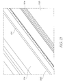
FIG. 27 is a plan view of the LCP channel molding;
FIGS. 28A and 28B are schematic section views of the LCP channel molding priming without a weir;
FIGS. 29A, 29B and 29C are schematic section views of the LCP channel molding priming with a weir;
FIG. 30 in an enlarged transverse perspective of the LCP molding with the position of the contact force and the reaction force;
FIG. 31 shows a reel of the IC attachment film;
FIG. 32 shows a section of the IC attach film between liners; and
FIG. 33 is a partial section view showing the laminate structure of the attachment film.
DETAILED DESCRIPTION OF THE PREFERRED EMBODIMENTS
Overview
FIG. 1 shows a printer 2 embodying the present invention. The main body 4 of the printer supports a media feed tray 14 at the back and a pivoting face 6 at the front. FIG. 1 shows the pivoting face 6 closed such that the display screen 8 is its upright viewing position. Control buttons 10 extend from the sides of the screen 8 for convenient operator input while viewing the screen. To print, a single sheet is drawn from the media stack 12 in the feed tray 14 and fed past the printhead (concealed within the printer). The printed sheet 16 is delivered through the printed media outlet slot 18.
FIG. 2 shows the pivoting front face 6 open to reveal the interior of the printer 2. Opening the front face of the printer exposes the printhead cartridge 96 installed within. The printhead cartridge 96 is secured in position by the cartridge engagement cams 20 that push it down to ensure that the ink coupling (described later) is fully engaged and the printhead ICs (described later) are correctly positioned adjacent the paper feed path. The cams 20 are manually actuated by the release lever 24. The front face 6 will not close, and hence the printer will not operate, until the release lever 24 is pushed down to fully engage the cams. Closing the pivoting face 6 engages the printer contacts 22 with the cartridge contacts 104.
FIG. 3 shows the printer 2 with the pivoting face 6 open and the printhead cartridge 96 removed. With the pivoting face 6 tilted forward, the user pulls the cartridge release lever 24 up to disengage the cams 20. This allows the handle 26 on the cartridge 96 to be gripped and pulled upwards. The upstream and downstream ink couplings 112A and 112B disengage from the printer conduits 142. This is described in greater detail below. To install a fresh cartridge, the process is reversed. New cartridges are shipped and sold in an unprimed condition. So to ready the printer for printing, the active fluidics system (described below) uses a downstream pump to prime the cartridge and printhead with ink.
In FIG. 4, the outer casing of the printer 2 has been removed to reveal the internals. A large ink tank 60 has separate reservoirs for all four different inks. The ink tank 60 is itself a replaceable cartridge that couples to the printer upstream of the shut off valve 66 (see FIG. 6). There is also a sump 92 for ink drawn out of the cartridge 96 by the pump 62. The printer fluidics system is described in detail with reference to FIG. 6. Briefly, ink from the tank 60 flows through the upstream ink lines 84 to the shut off valves 66 and on to the printer conduits 142. As shown in FIG. 5, when the cartridge 96 is installed, the pump 62 (driven by motor 196) can draw ink into the LCP molding 64 (see FIGS. 6 and 17 to 20) so that the printhead ICs 68 (again, see FIGS. 6 and 17 to 20) prime by capillary action. Excess ink drawn by the pump 62 is fed to a sump 92 housed with the ink tanks 60.
The total connector force between the cartridge contacts 104 and the printer contacts 22 is relatively high because of the number of contacts used. In the embodiment shown, the total contact force is 45 Newtons. This load is enough to flex and deform the cartridge. Turning briefly to FIG. 30, the internal structure of the chassis molding 100 is shown. The bearing surface 28 shown in FIG. 3 is schematically shown in FIG. 30. The compressive load of the printer contacts on the cartridge contacts 104 is represented with arrows. The reaction force at the bearing surface 28 is likewise represented with arrows. To maintain the structural integrity of the cartridge 96, the chassis molding 100 has a structural member 30 that extends in the plane of the connector force. To keep the reaction force acting in the plane of the connector force, the chassis also has a contact rib 32 that bears against the bearing surface 28. This keeps the load on the structural member 30 completely compressive to maximize the stiffness of the cartridge and minimize any flex.
Print Engine Pipeline
The print engine pipeline is a reference to the printer's processing of print data received from an external source and outputted to the printhead for printing. The print engine pipeline is described in detail in U.S. Ser. No. 11/014,769 filed Dec. 20, 2004, the disclosure of which is incorporated herein by reference.
Fluidic System
Traditionally printers have relied on the structure and components within the printhead, cartridge and ink lines to avoid fluidic problems. Some common fluidic problems are deprimed or dried nozzles, outgassing bubble artifacts and color mixing from cross contamination. Optimizing the design of the printer components to avoid these problems is a passive approach to fluidic control. Typically, the only active component used to correct these were the nozzle actuators themselves. However, this is often insufficient and or wastes a lot of ink in the attempt to correct the problem. The problem is exacerbated in pagewidth printheads because of the length and complexity of the ink conduits supplying the printhead ICs.
The Applicant has addressed this by developing an active fluidic system for the printer. Several such systems are described in detail in U.S. Ser. No. 11/677,049 the contents of which are incorporated herein by reference. FIG. 6 shows one of the single pump implementations of the active fluidic system which would be suitable for use with the printhead described in the present specification.
The fluidic architecture shown in FIG. 6 is a single ink line for one color only. A color printer would have separate lines (and of course separate ink tanks 60) for each ink color. As shown in FIG. 6, this architecture has a single pump 62 downstream of the LCP molding 64, and a shut off valve 66 upstream of the LCP molding. The LCP molding supports the printhead IC's 68 via the adhesive IC attach film 174 (see FIG. 25). The shut off valve 66 isolates the ink in the ink tank 60 from the printhead IC's 66 whenever the printer is powered down. This prevents any color mixing at the printhead IC's 68 from reaching the ink tank 60 during periods of inactivity. These issues are discussed in more detail in the cross referenced specification U.S. Ser. No. 11/677,049.
The ink tank 60 has a venting bubble point pressure regulator 72 for maintaining a relatively constant negative hydrostatic pressure in the ink at the nozzles. Bubble point pressure regulators within ink reservoirs are comprehensively described in co-pending U.S. Ser. No. 11/640,355 incorporated herein by reference. However, for the purposes of this description the regulator 72 is shown as a bubble outlet 74 submerged in the ink of the tank 60 and vented to atmosphere via sealed conduit 76 extending to an air inlet 78. As the printhead IC's 68 consume ink, the pressure in the tank 60 drops until the pressure difference at the bubble outlet 74 sucks air into the tank. This air forms a forms a bubble in the ink which rises to the tank's headspace. This pressure difference is the bubble point pressure and will depend on the diameter (or smallest dimension) of the bubble outlet 74 and the Laplace pressure of the ink meniscus at the outlet which is resisting the ingress of the air.
The bubble point regulator uses the bubble point pressure needed to generate a bubble at the submerged bubble outlet 74 to keep the hydrostatic pressure at the outlet substantially constant (there are slight fluctuations when the bulging meniscus of air forms a bubble and rises to the headspace in the ink tank). If the hydrostatic pressure at the outlet is at the bubble point, then the hydrostatic pressure profile in the ink tank is also known regardless of how much ink has been consumed from the tank. The pressure at the surface of the ink in the tank will decrease towards the bubble point pressure as the ink level drops to the outlet. Of course, once the outlet 74 is exposed, the head space vents to atmosphere and negative pressure is lost. The ink tank should be refilled, or replaced (if it is a cartridge) before the ink level reaches the bubble outlet 74.
The ink tank 60 can be a fixed reservoir that can be refilled, a replaceable cartridge or (as disclosed in 11/014,769 incorporated by reference) a refillable cartridge. To guard against particulate fouling, the outlet 80 of the ink tank 60 has a coarse filter 82. The system also uses a fine filter at the coupling to the printhead cartridge. As filters have a finite life, replacing old filters by simply replacing the ink cartridge or the printhead cartridge is particularly convenient for the user. If the filters are separate consumable items, regular replacement relies on the user's diligence.
When the bubble outlet 74 is at the bubble point pressure, and the shut off valve 66 is open, the hydrostatic pressure at the nozzles is also constant and less than atmospheric. However, if the shut off valve 66 has been closed for a period of time, outgassing bubbles may form in the LCP molding 64 or the printhead IC's 68 that change the pressure at the nozzles. Likewise, expansion and contraction of the bubbles from diurnal temperature variations can change the pressure in the ink line 84 downstream of the shut off valve 66. Similarly, the pressure in the ink tank can vary during periods of inactivity because of dissolved gases coming out of solution.
The downstream ink line 86 leading from the LCP 64 to the pump 62 can include an ink sensor 88 linked to an electronic controller 90 for the pump. The sensor 88 senses the presence or absence of ink in the downstream ink line 86. Alternatively, the system can dispense with the sensor 88, and the pump 62 can be configured so that it runs for an appropriate period of time for each of the various operations. This may adversely affect the operating costs because of increased ink wastage.
The pump 62 feeds into a sump 92 (when pumping in the forward direction). The sump 92 is physically positioned in the printer so that it is less elevated than the printhead ICs 68. This allows the column of ink in the downstream ink line 86 to ‘hang’ from the LCP 64 during standby periods, thereby creating a negative hydrostatic pressure at the printhead ICs 68. A negative pressure at the nozzles draws the ink meniscus inwards and inhibits color mixing. Of course, the peristaltic pump 62 needs to be stopped in an open condition so that there is fluid communication between the LCP 64 and the ink outlet in the sump 92.
Pressure differences between the ink lines of different colors can occur during periods of inactivity. Furthermore, paper dust or other particulates on the nozzle plate can wick ink from one nozzle to another. Driven by the slight pressure differences between each ink line, color mixing can occur while the printer is inactive. The shut off valve 66 isolates the ink tank 60 from the nozzle of the printhead IC's 68 to prevent color mixing extending up to the ink tank 60. Once the ink in the tank has been contaminated with a different color, it is irretrievable and has to be replaced.
The capper 94 is a printhead maintenance station that seals the nozzles during standby periods to avoid dehydration of the printhead ICs 68 as well as shield the nozzle plate from paper dust and other particulates. The capper 94 is also configured to wipe the nozzle plate to remove dried ink and other contaminants. Dehydration of the printhead ICs 68 occurs when the ink solvent, typically water, evaporates and increases the viscosity of the ink. If the ink viscosity is too high, the ink ejection actuators fail to eject ink drops. Should the capper seal be compromised, dehydrated nozzles can be a problem when reactivating the printer after a power down or standby period.
The problems outlined above are not uncommon during the operative life of a printer and can be effectively corrected with the relatively simple fluidic architecture shown in FIG. 6. It also allows the user to initially prime the printer, deprime the printer prior to moving it, or restore the printer to a known print ready state using simple trouble-shooting protocols. Several examples of these situations are described in detail in the above referenced U.S. Ser. No. 11/677,049.
Printhead Cartridge
The printhead cartridge 96 is shown in FIGS. 7 to 16A. FIG. 7 shows the cartridge 96 in its assembled and complete form. The bulk of the cartridge is encased in the cartridge chassis 100 and the chassis lid 102. A window in the chassis 100 exposes the cartridge contacts 104 that receive data from the print engine controller in the printer.
FIGS. 8 and 9 show the cartridge 96 with its snap on protective cover 98. The protective cover 98 prevents damaging contact with the electrical contacts 104 and the printhead IC's 68 (see FIG. 10). The user can hold the top of the cartridge 96 and remove the protective cover 98 immediately prior to installation in the printer.
FIG. 10 shows the underside and ‘back’ (with respect to the paper feed direction) of the printhead cartridge 96. The printhead contacts 104 are conductive pads on a flexible printed circuit board 108 that wraps around a curved support surface (discussed below in the description relating to the LCP moulding) to a line of wire bonds 110 at one side if the printhead IC's 68. On the other side of the printhead IC's 68 is a paper shield 106 to prevent direct contact with the media substrate.
FIG. 11 shows the underside and the ‘front’ of the printhead cartridge 96. The front of the cartridge has two ink couplings 112A and 112B at either end. Each ink coupling has four cartridge valves 114. When the cartridge is installed in the printer, the ink couplings 112A and 112B engage complementary ink supply interfaces (described in more detail below). The ink supply interfaces have printer conduits 142 which engage and open the cartridge valves 114. One of the ink couplings 112A is the upstream ink coupling and the other is the downstream coupling 112B. The upstream coupling 112A establishes fluid communication between the printhead IC's 68 and the ink supply 60 (see FIG. 6) and the downstream coupling 112B connects to the sump 92 (refer FIG. 6 again).
The various elevations of the printhead cartridge 96 are shown in FIG. 12. The plan view of the cartridge 96 also shows the location of the section views shown in FIGS. 14, 15 and 16.
FIG. 13 is an exploded perspective of the cartridge 96. The LCP molding 64 attaches to the underside of the cartridge chassis 100. In turn the flex PCB 108 attaches to the underside of the LCP molding 64 and wraps around one side to expose the printhead contacts 104. An inlet manifold and filter 116 and outlet manifold 118 attach to the top of the chassis 100. The inlet manifold and filter 116 connects to the LCP inlets 122 via elastomeric connectors 120. Likewise the LCP outlets 124 connect to the outlet manifold 118 via another set of elastomeric connectors 120. The chassis lid 102 encases the inlet and outlet manifolds in the chassis 100 from the top and the removable protective cover 98 snaps over the bottom to protect the contacts 104 and the printhead IC's (see FIG. 11).
Inlet and Filter Manifold
FIG. 14 is an enlarged section view taken along line 14-14 of FIG. 12. It shows the fluid path through one of the cartridge valves 114 of the upstream coupling 112A to the LCP molding 64. The cartridge valve 114 has an elastomeric sleeve 126 that is biased into sealing engagement with a fixed valve member 128. The cartridge valve 114 is opened by the printer conduit 142 (see FIG. 16) by compressing the elastomeric sleeve 126 such that it unseats from the fixed valve member 128 and allows ink to flow up to a roof channel 138 along the top of the inlet and filter manifold 116. The roof channel 138 leads to an upstream filter chamber 132 that has one wall defined by a filter membrane 130. Ink passes through the filter membrane 130 into the downstream filter chamber 134 and out to the LCP inlet 122. From there filtered ink flows along the LCP main channels 136 to feed into the printhead IC's (not shown).
Particular features and advantages of the inlet and filter manifold 116 will now be described with reference to FIG. 15. The exploded perspective of FIG. 15 best illustrates the compact design of the inlet and filter manifold 116. There are several aspects of the design that contribute to its compact form. Firstly, the cartridge valves are spaced close together. This is achieved by departing from the traditional configuration of self-sealing ink valves. Previous designs also used an elastomeric member biased into sealing engagement with a fixed member. However, the elastomeric member was either a solid shape that the ink would flow around, or in the form of a diaphragm if the ink flowed through it.
In a cartridge coupling, it is highly convenient for the cartridge valves to automatically open upon installation. This is most easily and cheaply provided by a coupling in which one valve has an elastomeric member which is engaged by a rigid member on the other valve. If the elastomeric member is in a diaphragm form, it usually holds itself against the central rigid member under tension. This provides an effective seal and requires relatively low tolerances. However, it also requires the elastomer element to have a wide peripheral mounting. The width of the elastomer will be a trade-off between the desired coupling force, the integrity of the seal and the material properties of the elastomer used.
As best shown in FIG. 16, the cartridge valves 114 of the present invention use elastomeric sleeves 126 that seal against the fixed valve member 128 under residual compression. The valve 114 opens when the cartridge is installed in the printer and the conduit end 148 of the printer valve 142 further compresses the sleeve 126. The collar 146 unseals from the fixed valve member 128 to connect the LCP 64 into the printer fluidic system (see FIG. 6) via the upstream and downstream ink coupling 112A and 112B. The sidewall of the sleeve is configured to bulge outwardly as collapsing inwardly can create a flow obstruction. As shown in FIG. 16, the sleeve 126 has a line of relative weakness around its mid-section that promotes and directs the buckling process. This reduces the force necessary to engage the cartridge with the printer, and ensures that the sleeve buckles outwardly.
The coupling is configured for ‘no-drip’ disengagement of the cartridge from the printer. As the cartridge is pulled upwards from the printer the elastomeric sleeve 126 pushes the collar 146 to seal against the fixed valve member 128. Once the sleeve 126 has sealed against the valve member 128 (thereby sealing the cartridge side of the coupling), the sealing collar 146 lifts together with the cartridge. This unseals the collar 146 from the end of the conduit 148. As the seal breaks an ink meniscus forms across the gap between the collar and the end of the conduit 148. The shape of the end of the fixed valve member 128 directs the meniscus to travel towards the middles of its bottom surface instead of pinning to a point. At the middle of the rounded bottom of the fixed valve member 128, the meniscus is driven to detach itself from the now almost horizontal bottom surface. To achieve the lowest possible energy state, the surface tension drives the detachment of the meniscus from the fixed valve member 128. The bias to minimize meniscus surface area is strong and so the detachment is complete with very little, if any, ink remaining on the cartridge valve 114. Any remaining ink is not enough a drop that can drip and stain prior to disposal of the cartridge.
When a fresh cartridge is installed in the printer, the air in conduit 150 will be entrained into the ink flow 152 and ingested by the cartridge. In light of this, the inlet manifold and filter assembly have a high bubble tolerance. Referring back to FIG. 15, the ink flows through the top of the fixed valve member 128 and into the roof channel 138. Being the most elevated point of the inlet manifold 116, the roof channels can trap the bubbles. However, bubbles may still flow into the filter inlets 158. In this case, the filter assembly itself is bubble tolerant.
Bubbles on the upstream side of the filter member 130 can affect the flow rate—they effectively reduce the wetted surface area on the dirty side of the filter membrane 130. The filter membranes have a long rectangular shape so even if an appreciable number of bubbles are drawn into the dirty side of the filter, the wetted surface area remains large enough to filter ink at the required flow rate. This is crucial for the high speed operation offered by the present invention.
While the bubbles in the upstream filter chamber 132 can not cross the filter membrane 130, bubbles from outgassing may generate bubbles in the downstream filter chamber 134. The filter outlet 156 is positioned at the bottom of the downstream filter chamber 134 and diagonally opposite the inlet 158 in the upstream chamber 132 to minimize the effects of bubbles in either chamber on the flow rate.
The filters 130 for each color are vertically stacked closely side-by-side. The partition wall 162 partially defines the upstream filter chamber 132 on one side, and partially defines the downstream chamber 134 of the adjacent color on the other side. As the filter chambers are so thin (for compact design), the filter membrane 130 can be pushed against the opposing wall of the downstream filter chamber 134. This effectively reduces the surface are of the filter membrane 130. Hence it is detrimental to maximum flowrate. To prevent this, the opposing wall of the downstream chamber 134 has a series of spacer ribs 160 to keep the membrane 130 separated from the wall.
Positioning the filter inlet and outlet at diagonally opposed corners also helps to purge the system of air during the initial prime of the system.
To reduce the risk of particulate contamination of the printhead, the filter membrane 130 is welded to the downstream side of a first partition wall before the next partition wall 162 is welded to the first partition wall. In this way, any small pieces of filter membrane 130 that break off during the welding process, will be on the ‘dirty’ side of the filter 130.
LCP Molding/Flex PCB/Printhead ICs
The LCP molding 64, flex PCB 108 and printhead ICs 68 assembly are shown in FIGS. 17 to 33. FIG. 17 is a perspective of the underside of the LCP molding 64 with the flex PCB and printhead ICs 68 attached. The LCP molding 64 is secured to the cartridge chassis 100 through countersunk holes 166 and 168. Hole 168 is an obround hole to accommodate any miss match in coefficients of thermal expansion (CTE) without bending the LCP. The printhead ICs 68 are arranged end to end in a line down the longitudinal extent of the LCP molding 64. The flex PCB 108 is wire bonded at one edge to the printhead ICs 68. The flex PCB 108 also secures to the LCP molding at the printhead IC edge as well as at the cartridge contacts 104 edge. Securing the flex PCB at both edges keeps it tightly held to the curved support surface 170 (see FIG. 19). This ensures that the flex PCB does not bend to a radius that is tighter than specified minimum, thereby reducing the risk that the conductive tracks through the flex PCB will fracture.
FIG. 18 is an enlarged view of Inset A shown in FIG. 17. It shows the line of wire bonding contacts 164 along the side if the flex PCB 108 and the line of printhead ICs 68.
FIG. 19 is an exploded perspective of the LCP/flex/printhead IC assembly showing the underside of each component. FIG. 20 is another exploded perspective, this time showing the topside of the components. The LCP molding 64 has an LCP channel molding 176 sealed to its underside. The printhead ICs 68 are attached to the underside of the channel molding 176 by adhesive IC attach film 174. On the topside of the LCP channel molding 176 are the LCP main channels 184. These are open to the ink inlet 122 and ink outlet 124 in the LCP molding 64. At the bottom of the LCP main channels 184 are a series of ink supply passages 182 leading to the printhead ICs 68. The adhesive IC attach film 174 has a series of laser drilled supply holes 186 so that the attachment side of each printhead IC 68 is in fluid communication with the ink supply passages 182. The features of the adhesive IC attach film are described in detail below with reference to FIGS. 31 to 33.
The LCP molding 64 has recesses 178 to accommodate electronic components 180 in the drive circuitry on the flex PCB 108. For optimal electrical efficiency and operation, the cartridge contacts 104 on the PCB 108 should be close to the printhead ICs 68. However, to keep the paper path adjacent the printhead straight instead of curved or angled, the cartridge contacts 104 need to be on the side of the cartridge 96. The conductive paths in the flex PCB are known as traces. As the flex PCB must bend around a corner, the traces can crack and break the connection. To combat this, the trace can be bifurcated prior to the bend and then reunited after the bend. If one branch of the bifurcated section cracks, the other branch maintains the connection. Unfortunately, splitting the trace into two and then joining it together again can give rise to electromagnetic interference problems that create noise in the circuitry.
Making the traces wider is not an effective solution as wider traces are not significantly more crack resistant. Once the crack has initiated in the trace, it will propagate across the entire width relatively quickly and easily. Careful control of the bend radius is more effective at minimizing trace cracking, as is minimizing the number of traces that cross the bend in the flex PCB.
Pagewidth printheads present additional complications because of the large array of nozzles that must fire in a relatively short time. Firing many nozzles at once places a large current load on the system. This can generate high levels of inductance through the circuits which can cause voltage dips that are detrimental to operation. To avoid this, the flex PCB has a series of capacitors that discharge during a nozzle firing sequence to relieve the current load on the rest of the circuitry. Because of the need to keep a straight paper path past the printhead ICs, the capacitors are traditionally attached to the flex PCB near the contacts on the side of the cartridge. Unfortunately, they create additional traces that risk cracking in the bent section of the flex PCB.
This is addressed by mounting the capacitors 180 (see FIG. 20) closely adjacent the printhead ICs 68 to reduce the chance of trace fracture. The paper path remains linear by recessing the capacitors and other components into the LCP molding 64. The relatively flat surface of the flex PCB 108 downstream of the printhead ICs 68 and the paper shield 172 mounted to the ‘front’ (with respect to the feed direction) of the cartridge 96 minimize the risk of paper jams.
Isolating the contacts from the rest of the components of the flex PCB minimizes the number of traces that extend through the bent section. This affords greater reliability as the chances of cracking reduce. Placing the circuit components next to the printhead IC means that the cartridge needs to be marginally wider and this is detrimental to compact design. However, the advantages provided by this configuration outweigh any drawbacks of a slightly wider cartridge. Firstly, the contacts can be larger as there are no traces from the components running in between and around the contacts. With larger contacts, the connection is more reliable and better able to cope with fabrication inaccuracies between the cartridge contacts and the printer-side contacts. This is particularly important in this case, as the mating contacts rely on users to accurately insert the cartridge.
Secondly, the edge of the flex PCB that wire bonds to the side of the printhead IC is not under residual stress and trying to peel away from the bend radius. The flex can be fixed to the support structure at the capacitors and other components so that the wire bonding to the printhead IC is easier to form during fabrication and less prone to cracking as it is not also being used to anchor the flex.
Thirdly, the capacitors are much closer to the nozzles of the printhead IC and so the electro-magnetic interference generated by the discharging capacitors is minimized.
FIG. 21 is an enlargement of the underside of the printhead cartridge 96 showing the flex PCB 108 and the printhead ICs 68. The wire bonding contacts 164 of the flex PCB 108 run parallel to the contact pads of the printhead ICs 68 on the underside of the adhesive IC attach film 174. FIG. 22 shows FIG. 21 with the printhead ICs 68 and the flex PCB removed to reveal the supply holes 186. The holes are arranged in four longitudinal rows. Each row delivers ink of one particular color and each row aligns with a single channel in the back of each printhead IC.
FIG. 23 shows the underside of the LCP channel molding 176 with the adhesive IC attach film 174 removed. This exposes the ink supply passages 182 that connect to the LCP main channels 184 (see FIG. 20) formed in the other side of the channel molding 176. It will be appreciated that the adhesive IC attach film 174 partly defines the supply passages 182 when it is stuck in place. It will also be appreciated that the attach film must be accurately positioned, as the individual supply passages 182 must align with the supply holes 186 laser drilled through the film 174.
FIG. 24 shows the underside of the LCP molding with the LCP channel molding removed. This exposes the array of blind cavities 200 that contain air when the cartridge is primed with ink in order to damp any pressure pulses. This is discussed in greater detail below.
Printhead IC Attach Film
Turning briefly to FIGS. 31 to 33, the adhesive IC attachment film is described in more detail. The film 174 is laser drilled and wound into a reel 198 for convenient incorporation in the printhead cartridge 96. For the purposes of handling and storage, the film 174 is two protective liners on either side. One is the existing liner 188 that is attached to the film prior to laser drilling. The other is a replacement liner 192 added after the drilling operation. The section of film 174 shown in FIG. 32 has some of the existing liner 188 removed to expose the supply holes 186. The replacement liner 192 on the other side of the film is added after the supply holes 186 have been laser drilled.
FIG. 33 shows the laminate structure of the film 174. The central web 190 provides the strength for the laminate. On either side is an adhesive layer 194. The adhesive layers 194 are covered with liners. The laser drilling forms holes 186 that extend from a first side of the film 174 and terminate somewhere in the liner 188 in the second side. The foraminous liner on the first side is removed and replaced with a replacement liner 192. The strip of film is then wound into a reel 198 (see FIG. 31) for storage and handling prior to attachment. When the printhead cartridge is assembled, suitable lengths are drawn from the reel 198, the liners removed and adhered to the underside of the LCP molding 64 such that the holes 186 are in registration with the correct ink supply passages 182 (see FIG. 25).
Enhanced Ink Supply to Printhead IC Ends
FIG. 25 shows the printhead ICs 68, superimposed on the ink supply holes 186 through the adhesive IC attach film 174, which are in turn superimposed on the ink supply passages 182 in the underside of the LCP channel molding 176. Adjacent printhead ICs 68 are positioned end to end on the bottom of the LCP channel molding 176 via the attach film 174. At the junction between adjacent printhead ICs 68, one of the ICs 68 has a ‘drop triangle’ 206 portion of nozzles in rows that are laterally displaced from the corresponding row in the rest of the nozzle array 220. This allows the edge of the printing from one printhead IC to be contiguous with the printing from the adjacent printhead IC. By displacing the drop triangle 206 of nozzles, the spacing (in a direction perpendicular to media feed) between adjacent nozzles remains unchanged regardless of whether the nozzles are on the same IC or either side of the junction on different ICs. This requires precise relative positioning of the adjacent printhead ICs 68, and the fiducial marks 204 are used to achieve this. The process can be time consuming but avoids artifacts in the printed image.
Unfortunately, some of the nozzles at the ends of a printhead IC 68 can be starved of ink relative to the bulk of the nozzles in the rest of the array 220. For example, the nozzles 222 can be supplied with ink from two ink supply holes. Ink supply hole 224 is the closest. However, if there is an obstruction or particularly heavy demand from nozzles to the left of the hole 224, the supply hole 226 is also proximate to the nozzles at 222, so there is little chance of these nozzles depriming from ink starvation.
In contrast, the nozzles 214 at the end of the printhead IC 68 would only be in fluid communication with the ink supply hole 216 were it not for the ‘additional’ ink supply hole 210 placed at the junction between the adjacent ICs 68. Having the additional ink supply hole 210 means that none of the nozzles are so remote from an ink supply hole that they risk ink starvation.
Ink supply holes 208 and 210 are both fed from a common ink supply passage 212. The ink supply passage 212 has the capacity to supply both holes as supply hole 208 only has nozzles to its left, and supply hole 210 only has nozzles to its right. Therefore, the total flowrate through supply passage 212 is roughly equivalent to a supply passage that feeds one hole only.
FIG. 25 also highlights the discrepancy between the number of channels (colors) in the ink supply—four channels—and the five channels 218 in the printhead IC 68. The third and fourth channels 218 in the back of the printhead IC 68 are fed from the same ink supply holes 186. These supply holes are somewhat enlarged to span two channels 218.
The reason for this is that the printhead IC 68 is fabricated for use in a wide range of printers and printhead configurations. These may have five color channels—CMYK and IR (infrared)—but other printers, such this design, may only be four channel printers, and others still may only be three channel (CC, MM and Y). In light of this, a single color channel may be fed to two of the printhead IC channels. The print engine controller (PEC) microprocessor can easily accommodate this into the print data sent to the printhead IC. Furthermore, supplying the same color to two nozzle rows in the IC provides a degree of nozzle redundancy that can used for dead nozzle compensation.
Pressure Pulses
Sharp spikes in the ink pressure occur when the ink flowing to the printhead is stopped suddenly. This can happen at the end of a print job or a page. The Assignee's high speed, pagewidth printheads need a high flow rate of supply ink during operation. Therefore, the mass of ink in the ink line to the nozzles is relatively large and moving at an appreciable rate.
Abruptly ending a print job, or simply at the end of a printed page, requires this relatively high volume of ink that is flowing relatively quickly to come to an immediate stop. However, suddenly arresting the ink momentum gives rise to a shock wave in the ink line. The LCP molding 64 (see FIG. 19) is particularly stiff and provides almost no flex as the column of ink in the line is brought to rest. Without any compliance in the ink line, the shock wave can exceed the Laplace pressure (the pressure provided by the surface tension of the ink at the nozzles openings to retain ink in the nozzle chambers) and flood the front surface of the printhead IC 68. If the nozzles flood, ink may not eject and artifacts appear in the printing.
Resonant pulses in the ink occur when the nozzle firing rate matches a resonant frequency of the ink line. Again, because of the stiff structure that define the ink line, a large proportion of nozzles for one color, firing simultaneously, can create a standing wave or resonant pulse in the ink line. This can result in nozzle flooding, or conversely nozzle deprime because of the sudden pressure drop after the spike, if the Laplace pressure is exceeded.
To address this, the LCP molding 64 incorporates a pulse damper to remove pressure spikes from the ink line. The damper may be an enclosed volume of gas that can be compressed by the ink. Alternatively, the damper may be a compliant section of the ink line that can elastically flex and absorb pressure pulses.
To minimize design complexity and retain a compact form, the invention uses compressible volumes of gas to damp pressure pulses. Damping pressure pulses using gas compression can be achieved with small volumes of gas. This preserves a compact design while avoiding any nozzle flooding from transient spikes in the ink pressure.
As shown in FIGS. 24 and 26, the pulse damper is not a single volume of gas for compression by pulses in the ink. Rather the damper is an array of cavities 200 distributed along the length of the LCP molding 64. A pressure pulse moving through an elongate printhead, such as a pagewidth printhead, can be damped at any point in the ink flow line. However, the pulse will cause nozzle flooding as it passes the nozzles in the printhead integrated circuit, regardless of whether it is subsequently dissipated at the damper. By incorporating a number of pulse dampers into the ink supply conduits immediately next to the nozzle array, any pressure spikes are damped at the site where they would otherwise cause detrimental flooding.
It can be seen in FIG. 26, that the air damping cavities 200 are arranged in four rows. Each row of cavities sits directly above the LCP main channels 184 in the LCP channel molding 176. Any pressure pulses in the ink in the main channels 184 act directly on the air in the cavities 200 and quickly dissipate.
Printhead Priming
Priming the cartridge will now be described with particular reference to the LCP channel molding 176 shown in FIG. 27. The LCP channel molding 176 is primed with ink by suction applied to the main channel outlets 232 from the pump of the fluidic system (see FIG. 6). The main channels 184 are filled with ink and then the ink supply passages 182 and printhead ICs 68 self prime by capillary action.
The main channels 184 are relatively long and thin. Furthermore the air cavities 200 must remain unprimed if they are to damp pressure pulses in the ink. This can be problematic for the priming process which can easily fill cavities 200 by capillary action or the main channel 184 can fail to fully prime because of trapped air. To ensure that the LCP channel molding 176 fully primes, the main channels 184 have a weir 228 at the downstream end prior to the outlet 232. To ensure that the air cavities 200 in the LCP molding 64 do not prime, they have openings with upstream edges shaped to direct the ink meniscus from traveling up the wall of the cavity.
These aspects of the cartridge are best described with reference FIGS. 28A, 28B and 29A to 29C. These figures schematically illustrate the priming process. FIGS. 28A and 28B show the problems that can occur if there is no weir in the main channels, whereas FIGS. 29A to 29C show the function of the weir 228.
FIGS. 28A and 28B are schematic section views through one of the main channels 184 of the LCP channel molding 176 and the line of air cavities 200 in the roof of the channel. Ink 238 is drawn through the inlet 230 and flows along the floor of the main channel 184. It is important to note that the advancing meniscus has a steeper contact angle with the floor of the channel 184. This gives the leading portion of the ink flow 238 a slightly bulbous shape. When the ink reaches the end of the channel 184, the ink level rises and the bulbous front contacts the top of the channel before the rest of the ink flow. As shown in FIG. 28B, the channel 184 has failed to fully prime, and the air is now trapped. This air pocket will remain and interfere with the operation of the printhead. The ink damping characteristics are altered and the air can be an ink obstruction.
In FIGS. 29A to 29C, the channel 184 has a weir 228 at the downstream end. As shown in FIG. 29A, the ink flow 238 pools behind the weir 228 and rises toward the top of the channel. The weir 228 has a sharp edge 240 at the top to act as a meniscus anchor point. The advancing meniscus pins to this anchor 240 so that the ink does not simply flow over the weir 228 as soon as the ink level is above the top edge.
As shown in FIG. 29B, the bulging meniscus makes the ink rise until it has filled the channel 184 to the top. With the ink sealing the cavities 200 into separate air pockets, the bulging ink meniscus at the weir 228 breaks from the sharp top edge 240 and fills the end of the channel 184 and the ink outlet 232 (see FIG. 29C). The sharp to edge 240 is precisely positioned so that the ink meniscus will bulge until the ink fills to the top of the channel 184, but does not allow the ink to bulge so much that it contacts part of the end air cavity 242. If the meniscus touches and pins to the interior of the end air cavity 242, it may prime with ink. Accordingly, the height of the weir and its position under the cavity is closely controlled. The curved downstream surface of the weir 228 ensures that there are no further anchor points that might allow the ink meniscus to bridge the gap to the cavity 242.
Another mechanism that the LCP uses to keep the cavities 200 unprimed is the shape of the upstream and downstream edges of the cavity openings. As shown in FIGS. 28A, 28B and 29A to 29C, all the upstream edges have a curved transition face 234 while the downstream edges 236 are sharp. An ink meniscus progressing along the roof of the channel 184 can pin to a sharp upstream edge and subsequently move upwards into the cavity by capillary action. A transition surface, and in particular a curved transition surface 234 at the upstream edge removes the strong anchor point that a sharp edge provides.
Similarly, the Applicant's work has found that a sharp downstream edge 236 will promote depriming if the cavity 200 has inadvertently filled with some ink. If the printer is bumped, jarred or tilted, or if the fluidic system has had to reverse flow for any reason, the cavities 200 may fully of partially prime. When the ink flows in its normal direction again, a sharp downstream edge 236 helps to draw the meniscus back to the natural anchor point (i.e. the sharp corner). In this way, management of the ink meniscus movement through the LCP channel molding 176 is a mechanism for correctly priming the cartridge.
The invention has been described here by way of example only. Skilled workers in this field will recognize many variations and modification which do not depart from the spirit and scope of the broad inventive concept. Accordingly, the embodiments described and shown in the accompanying figures are to be considered strictly illustrative and in no way restrictive on the invention.

Claims (12)

1. A printhead for an inkjet printer, the printhead comprising:
a printhead integrated circuit (IC) with a plurality of arrays of nozzles for ejecting ink; and
a support structure for supporting the printhead IC, the support structure having ink conduits formed therein, each ink conduit supplying one of the plurality of arrays of nozzles with ink, an upstream end of each ink conduit is supplied with ink from an ink supply and a downstream end of each ink conduit feeds to a waste ink outlet, a roof of each ink conduit having an array of cavities defined therein distributed along the length of each ink conduit, each ink conduit further having a weir proximal to the downstream end of the ink conduit for damming ink in the ink conduit, wherein a separate pocket of gas is captured in each cavity when the ink is dammed by the weir, the pockets of gas being compressed by pressure pulses in the ink within the ink conduits to dissipate the pressure pulses.
2. A printhead according to claim 1 wherein each of the cavities is partially defined by an ink meniscus when the ink conduits of the support structure are primed with ink.
3. A printhead according to claim 2 wherein each of the cavities is a blind recess with an opening facing one or more of the ink conduits.
4. A printhead according to claim 3 wherein the opening of each of the blind recesses faces one of the ink conduits only.
5. A printhead according to claim 4 wherein the opening of each of the blind recesses is configured to inhibit ink filling the recess by capillary action.
6. A printhead according to claim 1 wherein the openings to each respective cavity have an upstream edge and a downstream edge, the upstream edge contacting the ink before the downstream edge during initial priming of the ink conduits from the ink supply, and the upstream edge having a transition face between the conduit and the cavity interior, the transition face being configured to inhibit ink from filling the cavity and purging the gas by capillary action during initial priming of the ink conduit.
7. A printhead according to claim 6 wherein the ink conduits have channels extending longitudinally along the support structure between the upstream and downstream ends, and each of the channels have a series ink feed passages spaced along respective channels to provide fluid communication between the channel and the printhead IC.
8. A printhead according to claim 7 wherein the ink feed passages join to the channel along a wall of the channel that is opposite the wall including the openings to the cavities.
9. A printhead according to claim 8 wherein the support structure is a liquid crystal polymer (LCP).
10. A printhead according to claim 9 wherein the support structure is a two-part LCP moulding with the channels and the feed passages formed in one part and the cavities formed in the other part.
11. A printhead according to claim 10 wherein the support structure has a plurality of printhead ICs mounted end to end along one side face.
12. A printhead according to claim 11 wherein the printhead ICs are mounted to the side face via an interposed adhesive film having holes for fluid communication between the ink feed passages and the printhead ICs.
US11/688,863 2006-03-03 2007-03-21 Fluidically damped printhead Active 2030-06-29 US8025383B2 (en)

Priority Applications (3)

Application Number Priority Date Filing Date Title
US11/688,863 US8025383B2 (en) 2006-03-03 2007-03-21 Fluidically damped printhead
US11/741,766 US7721441B2 (en) 2006-03-03 2007-04-29 Method of fabricating a printhead integrated circuit attachment film
US12/778,931 US20100221671A1 (en) 2006-03-03 2010-05-12 Printhead integrated circuit attachment film

Applications Claiming Priority (8)

Application Number Priority Date Filing Date Title
AU2006901084 2006-03-03
AU2006901084A AU2006901084A0 (en) 2006-03-03 Methods and apparatus (SBF001P)
AU2006901287A AU2006901287A0 (en) 2006-03-07 Methods and apparatus (SBF002P)
AU2006901287 2006-03-07
AU2006201083 2006-03-15
AU2006201083A AU2006201083B2 (en) 2006-03-15 2006-03-15 Pulse damped fluidic architecture
US11/677,049 US7771029B2 (en) 2006-03-03 2007-02-21 Printer with active fluidic architecture
US11/688,863 US8025383B2 (en) 2006-03-03 2007-03-21 Fluidically damped printhead

Related Parent Applications (1)

Application Number Title Priority Date Filing Date
US11/677,049 Continuation-In-Part US7771029B2 (en) 2006-03-03 2007-02-21 Printer with active fluidic architecture

Related Child Applications (1)

Application Number Title Priority Date Filing Date
US11/741,766 Continuation-In-Part US7721441B2 (en) 2006-03-03 2007-04-29 Method of fabricating a printhead integrated circuit attachment film

Publications (2)

Publication Number Publication Date
US20070206056A1 US20070206056A1 (en) 2007-09-06
US8025383B2 true US8025383B2 (en) 2011-09-27

Family

ID=38458562

Family Applications (8)

Application Number Title Priority Date Filing Date
US11/677,051 Active 2028-04-20 US7658482B2 (en) 2006-03-03 2007-02-21 Printhead assembly with shut off valve for isolating the printhead
US11/677,049 Expired - Fee Related US7771029B2 (en) 2006-03-03 2007-02-21 Printer with active fluidic architecture
US11/677,050 Abandoned US20070206050A1 (en) 2006-03-03 2007-02-21 Printhead assembly with ink pump and shut off valve
US11/688,863 Active 2030-06-29 US8025383B2 (en) 2006-03-03 2007-03-21 Fluidically damped printhead
US12/276,400 Active US7669996B2 (en) 2006-03-03 2008-11-23 Inkjet printer with elongate array of nozzles and distributed pulse dampers
US12/697,266 Active US7967425B2 (en) 2006-03-03 2010-01-31 Printhead assembly with ink supply shut off
US12/709,505 Abandoned US20100149294A1 (en) 2006-03-03 2010-02-21 Inkjet printer with elongate nozzle array supplied through pulse damped conduits
US13/117,101 Abandoned US20110228017A1 (en) 2006-03-03 2011-05-26 Shut off valve for disconnecting a printhead from an ink supply

Family Applications Before (3)

Application Number Title Priority Date Filing Date
US11/677,051 Active 2028-04-20 US7658482B2 (en) 2006-03-03 2007-02-21 Printhead assembly with shut off valve for isolating the printhead
US11/677,049 Expired - Fee Related US7771029B2 (en) 2006-03-03 2007-02-21 Printer with active fluidic architecture
US11/677,050 Abandoned US20070206050A1 (en) 2006-03-03 2007-02-21 Printhead assembly with ink pump and shut off valve

Family Applications After (4)

Application Number Title Priority Date Filing Date
US12/276,400 Active US7669996B2 (en) 2006-03-03 2008-11-23 Inkjet printer with elongate array of nozzles and distributed pulse dampers
US12/697,266 Active US7967425B2 (en) 2006-03-03 2010-01-31 Printhead assembly with ink supply shut off
US12/709,505 Abandoned US20100149294A1 (en) 2006-03-03 2010-02-21 Inkjet printer with elongate nozzle array supplied through pulse damped conduits
US13/117,101 Abandoned US20110228017A1 (en) 2006-03-03 2011-05-26 Shut off valve for disconnecting a printhead from an ink supply

Country Status (10)

Country Link
US (8) US7658482B2 (en)
EP (2) EP1991422B1 (en)
JP (2) JP4681654B2 (en)
KR (2) KR101068705B1 (en)
CN (1) CN101287606B (en)
AT (1) ATE505332T1 (en)
AU (1) AU2007219700B2 (en)
CA (1) CA2642405C (en)
DE (1) DE602007013876D1 (en)
WO (1) WO2007098527A1 (en)

Cited By (6)

* Cited by examiner, † Cited by third party
Publication number Priority date Publication date Assignee Title
US20100149294A1 (en) * 2006-03-03 2010-06-17 Silverbrook Research Pty Ltd Inkjet printer with elongate nozzle array supplied through pulse damped conduits
US20110310186A1 (en) * 2006-03-03 2011-12-22 Silverbrook Research Pty Ltd Printhead support structure with cavities for pulse damping
WO2015071007A1 (en) 2013-11-15 2015-05-21 Memjet Technology Limited Modular printer having narrow print zone
US20170313068A1 (en) * 2016-05-02 2017-11-02 Memjet Technology Ltd. Inkjet printhead with flexible film compliance over fluid outlets
WO2018141565A1 (en) 2017-02-06 2018-08-09 Memjet Technology Limited Printhead having heated shield plate
US20200171838A1 (en) * 2016-05-02 2020-06-04 Memjet Technology Limited Method of inkjet printing with air-dampening of ink pressure fluctuations

Families Citing this family (46)

* Cited by examiner, † Cited by third party
Publication number Priority date Publication date Assignee Title
US7721441B2 (en) * 2006-03-03 2010-05-25 Silverbrook Research Pty Ltd Method of fabricating a printhead integrated circuit attachment film
US8523143B2 (en) * 2007-03-21 2013-09-03 Zamtec Ltd Detachable fluid coupling for inkjet printer
US7758177B2 (en) * 2007-03-21 2010-07-20 Silverbrook Research Pty Ltd High flowrate filter for inkjet printhead
WO2009049348A1 (en) * 2007-10-16 2009-04-23 Silverbrook Research Pty Ltd Printer with reservoir headspace pressure control
US8020980B2 (en) * 2007-10-16 2011-09-20 Silverbrook Research Pty Ltd Printer with reservoir headspace pressure control
US20090179977A1 (en) * 2008-01-16 2009-07-16 Silverbrook Research Pty Ltd Compact ink filter assembly
EP2240325B1 (en) * 2008-02-11 2012-10-17 Hewlett-Packard Development Company, L.P. Self-cleaning ink supply systems
US8066359B2 (en) * 2008-03-03 2011-11-29 Silverbrook Research Pty Ltd Ink supply system with float valve chamber
EP2326507A4 (en) * 2008-08-19 2012-02-22 Silverbrook Res Pty Ltd Leak tester for a carrier for printhead integrated circuitry
US7984640B2 (en) 2008-08-19 2011-07-26 Silverbrook Research Pty Ltd. Pressure-based tester for a platform assembly
CN102186675B (en) * 2008-10-14 2014-05-14 惠普开发有限公司 Fluid-jet dispensing device
CA2742314C (en) * 2008-12-19 2013-10-22 Silverbrook Research Pty Ltd Ink manifold with multiple conduit shut off valve
US8025374B2 (en) 2008-12-19 2011-09-27 Silverbrook Research Pty Ltd Ink manifold with multiple conduit shut off valve
JP5282654B2 (en) * 2009-05-13 2013-09-04 株式会社リコー Image forming apparatus
EP2432641A4 (en) 2009-05-17 2012-10-10 Hewlett Packard Development Co Fluid-ejection printhead die having mixing barrier
US8323993B2 (en) * 2009-07-27 2012-12-04 Zamtec Limited Method of fabricating inkjet printhead assembly having backside electrical connections
US20110025774A1 (en) * 2009-07-31 2011-02-03 Silverbrook Research Pty Ltd Wide format printer with pump to prime multiple printheads
US8500226B2 (en) 2010-05-17 2013-08-06 Zamtec Ltd System for sensing capacity state of liquid container
US8517523B2 (en) 2010-05-17 2013-08-27 Zamtec Ltd Septum assembly for fluid container
US10132303B2 (en) 2010-05-21 2018-11-20 Hewlett-Packard Development Company, L.P. Generating fluid flow in a fluidic network
US9395050B2 (en) 2010-05-21 2016-07-19 Hewlett-Packard Development Company, L.P. Microfluidic systems and networks
US9963739B2 (en) 2010-05-21 2018-05-08 Hewlett-Packard Development Company, L.P. Polymerase chain reaction systems
WO2011146069A1 (en) 2010-05-21 2011-11-24 Hewlett-Packard Development Company, L.P. Fluid ejection device including recirculation system
JP5471892B2 (en) * 2010-06-29 2014-04-16 ブラザー工業株式会社 Liquid discharge head and liquid discharge apparatus having the same
US20120033019A1 (en) 2010-08-09 2012-02-09 Toshiba Tec Kabushiki Kaisha Inkjet recording apparatus and inkjet recording method
US8939531B2 (en) * 2010-10-28 2015-01-27 Hewlett-Packard Development Company, L.P. Fluid ejection assembly with circulation pump
JP2012179894A (en) * 2011-02-07 2012-09-20 Sii Printek Inc Pressure damper, liquid jet head, and liquid jet device
WO2012134486A1 (en) * 2011-03-31 2012-10-04 Hewlett-Packard Development Company, L.P. Fluidic devices, bubble generators and fluid control methods
JP5821326B2 (en) * 2011-06-28 2015-11-24 富士ゼロックス株式会社 Liquid supply mechanism and image forming apparatus
US8888208B2 (en) 2012-04-27 2014-11-18 R.R. Donnelley & Sons Company System and method for removing air from an inkjet cartridge and an ink supply line
TWI600550B (en) * 2012-07-09 2017-10-01 滿捷特科技公司 Printer having ink delivery system with air compliance chamber
CN103625111B (en) * 2012-08-27 2016-09-28 研能科技股份有限公司 Page width ink jet printing equipment
ITVI20120276A1 (en) 2012-10-19 2014-04-20 New System Srl COMPENSATION DEVICE FOR A PRINT HEAD AND PRINT GROUP INCLUDING SUCH COMPENSATION DEVICE
EP2783862B1 (en) * 2013-03-28 2019-05-08 Brother Kogyo Kabushiki Kaisha Liquid cartridge
TWI626168B (en) 2013-07-25 2018-06-11 滿捷特科技公司 Method of inkjet printing and maintaining nozzle hydration
WO2015060828A1 (en) * 2013-10-22 2015-04-30 Hewlett-Packard Development Company, L.P. Controlling an ink flow to a print head
US9895888B2 (en) 2014-04-22 2018-02-20 Hewlett-Packard Development Company, L.P. Fluid flow structure
JP2017537000A (en) * 2014-10-31 2017-12-14 ヒューレット−パッカード デベロップメント カンパニー エル.ピー.Hewlett‐Packard Development Company, L.P. Fluid ejection device
CN107206801B (en) * 2015-01-30 2018-11-02 惠普发展公司,有限责任合伙企业 Valve for printing-fluid supply system
JP6860333B2 (en) * 2016-01-08 2021-04-14 キヤノン株式会社 Liquid discharge head and recording device
EP3356148B1 (en) 2016-02-05 2020-11-04 Hewlett-Packard Development Company, L.P. Printheads
CN207291314U (en) 2016-05-09 2018-05-01 R.R.当纳利父子公司 Ink feeding unit
US10843480B2 (en) * 2018-02-23 2020-11-24 Canon Kabushiki Kaisha Inkjet printing apparatus and control method of inkjet printing apparatus
EP3921171A1 (en) 2019-02-06 2021-12-15 Hewlett-Packard Development Company, L.P. Fluid ejection device with a carrier having a slot
WO2020222766A1 (en) * 2019-04-29 2020-11-05 Hewlett-Packard Development Company, L.P. Fluidic dies with conductive members
EP4003739A4 (en) * 2019-07-31 2023-04-26 Hewlett-Packard Development Company, L.P. Printing fluid circulation

Citations (47)

* Cited by examiner, † Cited by third party
Publication number Priority date Publication date Assignee Title
US1778439A (en) 1924-06-26 1930-10-14 Gen Electric Vapor Lamp Co Retarded-circuit maker and breaker
US2030452A (en) 1935-04-23 1936-02-11 Camel Pen Company Soluble ink fountain pen
JPS5732975A (en) * 1980-08-08 1982-02-22 Seiko Epson Corp Ink jet head with pressure damper function
US4429713A (en) 1980-11-06 1984-02-07 Argus Verwaltungsgesellschaft Mbh Snap closure coupling for flowing-media ducts
US4512766A (en) 1982-12-08 1985-04-23 Whitman Medical Corporation Catheter valve
JPS61169254A (en) * 1985-01-23 1986-07-30 Nec Corp Drop on-demand type ink jet head
US5776113A (en) 1996-03-29 1998-07-07 Becton Dickinson And Company Valved PRN adapter for medical access devices
US5796419A (en) 1995-12-04 1998-08-18 Hewlett-Packard Company Self-sealing fluid interconnect
US6063062A (en) 1997-04-18 2000-05-16 Paradis; Joseph R. Universal luer activatable and swabbable antireflux valve
US6168137B1 (en) 1996-12-30 2001-01-02 Joseph R. Paradis Swabbable check valve
US20020000372A1 (en) 1998-07-10 2002-01-03 Pedersen John M. Dry contact assemblies, methods for making dry contact assemblies, and plating machines with dry contact assemblies for plating microelectronic workpieces
US20020008741A1 (en) * 1998-11-14 2002-01-24 Stephen Temple Droplet deposition apparatus
US20020027071A1 (en) 1998-11-30 2002-03-07 Applied Materials, Inc. Inflatable compliant bladder assembly
US6361155B1 (en) 1999-06-23 2002-03-26 Nec Corporation Ink jet recording head and method for manufacturing the same
JP2002239304A (en) 2001-02-21 2002-08-27 Nippon Steel Corp Foaming preventing structure of seawater discharge passage
US6460986B2 (en) 2000-01-26 2002-10-08 Seiko Epson Corporation Head unit for an ink jet printer
US6568802B2 (en) * 1998-08-07 2003-05-27 Investronica Sistemas S.A. Ink feeding circuit device for raster drawing machines
US6572592B1 (en) 1991-12-18 2003-06-03 Icu Medical, Inc. Medical valve and method of use
US6685305B2 (en) 2001-04-11 2004-02-03 Fuji Xerox Co., Ltd. Ink jet recording head and ink jet recording apparatus using this head
US6752492B2 (en) * 1999-08-24 2004-06-22 Canon Kabushiki Kaisha Print head and ink jet printing apparatus
US6805438B2 (en) * 2000-12-07 2004-10-19 Brother Kogyo Kabushiki Kaisha Ink jet printer
US6905202B2 (en) 2002-02-22 2005-06-14 Matsushita Electric Industrial Co., Ltd. Ink-jet head and recording apparatus
US20050134663A1 (en) 2003-11-25 2005-06-23 Brother Kogyo Kabushiki Kaisha Ink cartridge
EP1552937A2 (en) 2004-01-07 2005-07-13 Xerox Corporation Pressure pump system
US20050151801A1 (en) 2004-01-08 2005-07-14 Eastman Kodak Company Ink delivery system apparatus and method
US20050185020A1 (en) 2004-02-20 2005-08-25 Fuji Photo Film Co., Ltd. Liquid ejection head and method of producing the same
US20050225590A1 (en) 2000-05-24 2005-10-13 Silverbrook Research Pty Ltd. Filtered air supply for nozzle guard
US6955418B2 (en) 2002-06-26 2005-10-18 Brother Kogyo Kabushiki Kaisha Ink-jet printhead
EP1591254A2 (en) 2004-04-26 2005-11-02 Hewlett-Packard Development Company, L.P. Hybrid ink delivery system
US20050248628A1 (en) 2004-01-23 2005-11-10 Brother Kogyo Kabushiki Kaisha Injet printhead having externally-connected terminations structured to be resistant to damage
US20050270342A1 (en) 2004-06-07 2005-12-08 Canon Kabushiki Kaisha Liquid supplying apparatus and liquid housing container
US6997053B2 (en) 2003-08-27 2006-02-14 The Boc Group, Inc. Systems and methods for measurement of low liquid flow rates
US7004576B2 (en) 2002-09-19 2006-02-28 Brother Kogyo Kabushiki Kaisha Ink-jet printhead
WO2006030235A2 (en) 2004-09-18 2006-03-23 Xaar Technology Limited Fluid supply method and apparatus
US20060066697A1 (en) 2004-09-28 2006-03-30 Fuji Photo Film Co., Ltd. Image forming apparatus
US20060132666A1 (en) 2004-12-22 2006-06-22 Sharp Kabushiki Kaisha Substrate for display device and manufacturing method thereof
US20060170735A1 (en) 2005-01-28 2006-08-03 Hong Young-Ki Piezoelectric inkjet printhead having temperature sensor and method of making the same
US20060181581A1 (en) 2005-02-17 2006-08-17 Chang-Hoon Jung Piezoelectric inkjet printhead and method of manufacturing the same
US7121650B2 (en) 2001-12-18 2006-10-17 Samsung Electronics Co., Ltd. Piezoelectric ink-jet printhead
US7163282B2 (en) 2003-06-20 2007-01-16 Seiko Epson Corporation Valve unit and liquid ejecting apparatus
US20070206056A1 (en) 2006-03-03 2007-09-06 Silverbrook Research Pty Ltd Fluidically damped printhead
US7357478B2 (en) 2005-01-26 2008-04-15 Seiko Epson Corporation Liquid ejection apparatus and method for controlling liquid ejection apparatus
US7364265B1 (en) * 2007-03-21 2008-04-29 Silverbrook Research Pty Ltd Printhead with enhanced ink supply to elongate printhead IC ends
US20080231661A1 (en) 2007-03-21 2008-09-25 Silverbrook Research Pty Ltd Printhead with meniscus anchor for controlled priming
US20080231660A1 (en) * 2007-03-21 2008-09-25 Silverbrook Research Pty Ltd Printhead with ink conduit weir for priming control
US7475976B2 (en) * 2006-03-03 2009-01-13 Silverbrook Research Pty Ltd Printhead with elongate array of nozzles and distributed pulse dampers
US7837297B2 (en) 2006-03-03 2010-11-23 Silverbrook Research Pty Ltd Printhead with non-priming cavities for pulse damping

Family Cites Families (63)

* Cited by examiner, † Cited by third party
Publication number Priority date Publication date Assignee Title
US766996A (en) * 1903-06-11 1904-08-09 Acme Gas Company Safety-gage for liquids.
US4422080A (en) * 1981-12-17 1983-12-20 International Business Machines Ink jet printing method and apparatus
US4764449A (en) * 1985-11-01 1988-08-16 The Chromaline Corporation Adherent sandblast photoresist laminate
US4730197A (en) * 1985-11-06 1988-03-08 Pitney Bowes Inc. Impulse ink jet system
JPS6337955A (en) * 1986-08-01 1988-02-18 Ricoh Co Ltd Solenoid valve control circuit of ink jet printer
JPH02155745A (en) * 1988-12-09 1990-06-14 Canon Inc Liquid ejection recording device
CA2009631C (en) * 1989-02-17 1994-09-20 Shigeo Nonoyama Pressure damper of an ink jet printer
JP3127581B2 (en) * 1992-06-26 2001-01-29 セイコーエプソン株式会社 Ink jet recording apparatus and operation method
JP3158671B2 (en) * 1992-07-07 2001-04-23 セイコーエプソン株式会社 Ink jet head and driving method thereof
EP0579399A2 (en) * 1992-07-09 1994-01-19 Pilkington Plc Glass substrate for a magnetic disc and manufacture thereof
EP0591989B1 (en) * 1992-10-09 2000-01-26 Canon Kabushiki Kaisha Ink jet printing head and printing apparatus using same
US5585826A (en) * 1993-04-30 1996-12-17 Hewlett-Packard Company Service station for simultaneous capping/wiping of multiple inkjet cartridges having different inks
JP3136860B2 (en) * 1993-08-09 2001-02-19 富士ゼロックス株式会社 Ink supply device
JPH0789088A (en) * 1993-09-22 1995-04-04 Fuji Xerox Co Ltd Ink supplying device
JP3087535B2 (en) * 1993-09-29 2000-09-11 日本電気株式会社 Inkjet cartridge
US5565900A (en) * 1994-02-04 1996-10-15 Hewlett-Packard Company Unit print head assembly for ink-jet printing
JP3247558B2 (en) * 1994-11-07 2002-01-15 キヤノンアプテックス株式会社 Printer
US5758575A (en) * 1995-06-07 1998-06-02 Bemis Company Inc. Apparatus for printing an electrical circuit component with print cells in liquid communication
JP3382432B2 (en) * 1995-10-11 2003-03-04 キヤノン株式会社 Ink jet recording device
US6257714B1 (en) 1995-10-27 2001-07-10 Hewlett-Packard Company Method and apparatus for removing air from an inkjet print cartridge
US5812155A (en) * 1995-10-27 1998-09-22 Hewlett-Packard Company Apparatus for removing air from an ink-jet print cartridge
JPH09327924A (en) * 1996-06-12 1997-12-22 Brother Ind Ltd Nozzle plate
JPH1158736A (en) * 1997-08-20 1999-03-02 Ricoh Co Ltd Ink jet head and manufacture thereof
US6033060A (en) * 1997-08-29 2000-03-07 Topaz Technologies, Inc. Multi-channel ink supply pump
JPH11115212A (en) * 1997-10-14 1999-04-27 Seiko Epson Corp Ink jet recorder
US6082851A (en) * 1997-11-14 2000-07-04 Canon Kabushiki Kaisha Liquid ejection printing apparatus and liquid supply method to be employed in the same
JPH11170573A (en) * 1997-12-15 1999-06-29 Fuji Xerox Co Ltd Ink jet recording apparatus
US5980362A (en) * 1998-02-27 1999-11-09 Interface, Inc. Stencil for use in sandblasting stone objects
US6116726A (en) * 1998-05-28 2000-09-12 Hewlett-Packard Company Ink jet printer cartridge with inertially-driven air evacuation apparatus and method
JP2000203055A (en) * 1999-01-08 2000-07-25 Pilot Corp Ink cartridge
JP4350187B2 (en) 1999-01-14 2009-10-21 株式会社キーエンス Inkjet recording device
JP2000211156A (en) * 1999-01-27 2000-08-02 Fuji Xerox Co Ltd Ink jet recorder
JP2001199082A (en) * 1999-10-08 2001-07-24 Seiko Epson Corp Ink cartridge, ink jet recording apparatus and method for fitting ink cartridge
US6655786B1 (en) * 2000-10-20 2003-12-02 Silverbrook Research Pty Ltd Mounting of printhead in support member of six color inkjet modular printhead
JP4188080B2 (en) 2000-10-23 2008-11-26 エイプリオン・ディジタル・リミテッド Closed ink delivery system and method with printhead ink pressure control
JP4247704B2 (en) * 2001-09-11 2009-04-02 セイコーエプソン株式会社 Droplet discharge apparatus and liquid filling method thereof, and device manufacturing apparatus and device manufacturing method
US6830325B2 (en) * 2002-02-15 2004-12-14 Brother Kogyo Kabushiki Kaisha Ink-jet head
JP3880418B2 (en) * 2002-02-21 2007-02-14 日東電工株式会社 Method for sticking and fixing double-sided adhesive sheet and touch panel to display device
KR100471165B1 (en) * 2002-05-07 2005-03-08 삼성전자주식회사 Nonvolatile Memory Device With Non-planar Gate-Insulating Layer And Method Of Fabricating The Same
JP4252794B2 (en) * 2002-11-27 2009-04-08 エスアイアイ・プリンテック株式会社 Inkjet printer, ink supply method, and printhead maintenance method
JP2004188636A (en) * 2002-12-09 2004-07-08 Canon Inc Ink storage part, ink, inkjet recording apparatus, and inkjet recording method
US7087279B2 (en) * 2003-07-17 2006-08-08 3M Innovative Properties Company Adhesives and release liners with pyramidal structures
JP4522086B2 (en) * 2003-12-15 2010-08-11 キヤノン株式会社 Beam, beam manufacturing method, ink jet recording head including beam, and ink jet recording head manufacturing method
US7448734B2 (en) * 2004-01-21 2008-11-11 Silverbrook Research Pty Ltd Inkjet printer cartridge with pagewidth printhead
WO2005070679A1 (en) * 2004-01-21 2005-08-04 Silverbrook Research Pty Ltd Printhead assembly and printhead module for same
US7097274B2 (en) * 2004-01-30 2006-08-29 Hewlett-Packard Development Company, L.P. Removing gas from a printhead
JP2005225198A (en) * 2004-02-16 2005-08-25 Sony Corp Liquid discharging performance maintenance method and liquid discharging apparatus
JP4049105B2 (en) * 2004-02-24 2008-02-20 セイコーエプソン株式会社 Wiping device, droplet discharge device, electro-optical device, method of manufacturing electro-optical device, and electronic apparatus
US7191520B2 (en) * 2004-03-05 2007-03-20 Eastman Kodak Company Method of optmizing inkjet printheads using a plasma-etching process
US20050250346A1 (en) * 2004-05-06 2005-11-10 Applied Materials, Inc. Process and apparatus for post deposition treatment of low k dielectric materials
EP1778698A4 (en) * 2004-08-09 2009-07-15 Silverbrook Res Pty Ltd Synthetically expedient water-dispersible ir dyes having improved lightfastness
JP2006095915A (en) * 2004-09-30 2006-04-13 Brother Ind Ltd Inkjet head, relay substrate, compound substrate, method for producing inkjet head, and method for producing compound substrate
JP4106048B2 (en) * 2004-10-25 2008-06-25 松下電器産業株式会社 Semiconductor device manufacturing method and semiconductor device
JP4290154B2 (en) * 2004-12-08 2009-07-01 キヤノン株式会社 Liquid discharge recording head and ink jet recording apparatus
JP4306605B2 (en) * 2004-12-22 2009-08-05 ブラザー工業株式会社 Inkjet head manufacturing method
JP2006286788A (en) * 2005-03-31 2006-10-19 Fujitsu Ltd Semiconductor apparatus and its manufacturing method
JP4506717B2 (en) * 2005-07-20 2010-07-21 セイコーエプソン株式会社 Droplet discharge head and droplet discharge apparatus
US7262134B2 (en) * 2005-09-01 2007-08-28 Micron Technology, Inc. Microfeature workpieces and methods for forming interconnects in microfeature workpieces
JP2007069532A (en) * 2005-09-08 2007-03-22 Fujifilm Corp Method for manufacturing liquid delivery head and image formation device
JP2007152621A (en) * 2005-12-01 2007-06-21 Seiko Epson Corp Liquid droplet jet head and method for manufacturing the same
JP4816070B2 (en) * 2005-12-27 2011-11-16 ブラザー工業株式会社 Inkjet head manufacturing method
US7721441B2 (en) * 2006-03-03 2010-05-25 Silverbrook Research Pty Ltd Method of fabricating a printhead integrated circuit attachment film
KR100723428B1 (en) * 2006-05-30 2007-05-30 삼성전자주식회사 Inkjet printhead and method of manufacturing the same

Patent Citations (51)

* Cited by examiner, † Cited by third party
Publication number Priority date Publication date Assignee Title
US1778439A (en) 1924-06-26 1930-10-14 Gen Electric Vapor Lamp Co Retarded-circuit maker and breaker
US2030452A (en) 1935-04-23 1936-02-11 Camel Pen Company Soluble ink fountain pen
JPS5732975A (en) * 1980-08-08 1982-02-22 Seiko Epson Corp Ink jet head with pressure damper function
US4429713A (en) 1980-11-06 1984-02-07 Argus Verwaltungsgesellschaft Mbh Snap closure coupling for flowing-media ducts
US4512766A (en) 1982-12-08 1985-04-23 Whitman Medical Corporation Catheter valve
JPS61169254A (en) * 1985-01-23 1986-07-30 Nec Corp Drop on-demand type ink jet head
US6572592B1 (en) 1991-12-18 2003-06-03 Icu Medical, Inc. Medical valve and method of use
US5796419A (en) 1995-12-04 1998-08-18 Hewlett-Packard Company Self-sealing fluid interconnect
US5776113A (en) 1996-03-29 1998-07-07 Becton Dickinson And Company Valved PRN adapter for medical access devices
US6168137B1 (en) 1996-12-30 2001-01-02 Joseph R. Paradis Swabbable check valve
US6063062A (en) 1997-04-18 2000-05-16 Paradis; Joseph R. Universal luer activatable and swabbable antireflux valve
US20020000372A1 (en) 1998-07-10 2002-01-03 Pedersen John M. Dry contact assemblies, methods for making dry contact assemblies, and plating machines with dry contact assemblies for plating microelectronic workpieces
US6568802B2 (en) * 1998-08-07 2003-05-27 Investronica Sistemas S.A. Ink feeding circuit device for raster drawing machines
US20020008741A1 (en) * 1998-11-14 2002-01-24 Stephen Temple Droplet deposition apparatus
US20020027071A1 (en) 1998-11-30 2002-03-07 Applied Materials, Inc. Inflatable compliant bladder assembly
US6361155B1 (en) 1999-06-23 2002-03-26 Nec Corporation Ink jet recording head and method for manufacturing the same
US6752492B2 (en) * 1999-08-24 2004-06-22 Canon Kabushiki Kaisha Print head and ink jet printing apparatus
US6460986B2 (en) 2000-01-26 2002-10-08 Seiko Epson Corporation Head unit for an ink jet printer
US20050225590A1 (en) 2000-05-24 2005-10-13 Silverbrook Research Pty Ltd. Filtered air supply for nozzle guard
US6805438B2 (en) * 2000-12-07 2004-10-19 Brother Kogyo Kabushiki Kaisha Ink jet printer
JP2002239304A (en) 2001-02-21 2002-08-27 Nippon Steel Corp Foaming preventing structure of seawater discharge passage
US6685305B2 (en) 2001-04-11 2004-02-03 Fuji Xerox Co., Ltd. Ink jet recording head and ink jet recording apparatus using this head
US7121650B2 (en) 2001-12-18 2006-10-17 Samsung Electronics Co., Ltd. Piezoelectric ink-jet printhead
US6905202B2 (en) 2002-02-22 2005-06-14 Matsushita Electric Industrial Co., Ltd. Ink-jet head and recording apparatus
US6955418B2 (en) 2002-06-26 2005-10-18 Brother Kogyo Kabushiki Kaisha Ink-jet printhead
US7004576B2 (en) 2002-09-19 2006-02-28 Brother Kogyo Kabushiki Kaisha Ink-jet printhead
US7163282B2 (en) 2003-06-20 2007-01-16 Seiko Epson Corporation Valve unit and liquid ejecting apparatus
US6997053B2 (en) 2003-08-27 2006-02-14 The Boc Group, Inc. Systems and methods for measurement of low liquid flow rates
US20050134663A1 (en) 2003-11-25 2005-06-23 Brother Kogyo Kabushiki Kaisha Ink cartridge
EP1552937A2 (en) 2004-01-07 2005-07-13 Xerox Corporation Pressure pump system
US20050151801A1 (en) 2004-01-08 2005-07-14 Eastman Kodak Company Ink delivery system apparatus and method
US20050248628A1 (en) 2004-01-23 2005-11-10 Brother Kogyo Kabushiki Kaisha Injet printhead having externally-connected terminations structured to be resistant to damage
US20050185020A1 (en) 2004-02-20 2005-08-25 Fuji Photo Film Co., Ltd. Liquid ejection head and method of producing the same
EP1591254A2 (en) 2004-04-26 2005-11-02 Hewlett-Packard Development Company, L.P. Hybrid ink delivery system
US7311388B2 (en) 2004-06-07 2007-12-25 Canon Kabsuhiki Kaisha Liquid supplying apparatus and liquid housing container
US20050270342A1 (en) 2004-06-07 2005-12-08 Canon Kabushiki Kaisha Liquid supplying apparatus and liquid housing container
WO2006030235A2 (en) 2004-09-18 2006-03-23 Xaar Technology Limited Fluid supply method and apparatus
US20060066697A1 (en) 2004-09-28 2006-03-30 Fuji Photo Film Co., Ltd. Image forming apparatus
US20060132666A1 (en) 2004-12-22 2006-06-22 Sharp Kabushiki Kaisha Substrate for display device and manufacturing method thereof
US7357478B2 (en) 2005-01-26 2008-04-15 Seiko Epson Corporation Liquid ejection apparatus and method for controlling liquid ejection apparatus
US20060170735A1 (en) 2005-01-28 2006-08-03 Hong Young-Ki Piezoelectric inkjet printhead having temperature sensor and method of making the same
US20060181581A1 (en) 2005-02-17 2006-08-17 Chang-Hoon Jung Piezoelectric inkjet printhead and method of manufacturing the same
US20070206056A1 (en) 2006-03-03 2007-09-06 Silverbrook Research Pty Ltd Fluidically damped printhead
US7475976B2 (en) * 2006-03-03 2009-01-13 Silverbrook Research Pty Ltd Printhead with elongate array of nozzles and distributed pulse dampers
US7669996B2 (en) * 2006-03-03 2010-03-02 Silverbrook Research Pty Ltd Inkjet printer with elongate array of nozzles and distributed pulse dampers
US7837297B2 (en) 2006-03-03 2010-11-23 Silverbrook Research Pty Ltd Printhead with non-priming cavities for pulse damping
US20110025787A1 (en) 2006-03-03 2011-02-03 Silverbrook Research Pty Ltd Printhead support structure with cavities for pulse damping
US7364265B1 (en) * 2007-03-21 2008-04-29 Silverbrook Research Pty Ltd Printhead with enhanced ink supply to elongate printhead IC ends
US20080231661A1 (en) 2007-03-21 2008-09-25 Silverbrook Research Pty Ltd Printhead with meniscus anchor for controlled priming
US20080231660A1 (en) * 2007-03-21 2008-09-25 Silverbrook Research Pty Ltd Printhead with ink conduit weir for priming control
US7819507B2 (en) * 2007-03-21 2010-10-26 Silverbrook Research Pty Ltd Printhead with meniscus anchor for controlled priming

Cited By (27)

* Cited by examiner, † Cited by third party
Publication number Priority date Publication date Assignee Title
US20100149294A1 (en) * 2006-03-03 2010-06-17 Silverbrook Research Pty Ltd Inkjet printer with elongate nozzle array supplied through pulse damped conduits
US20110310186A1 (en) * 2006-03-03 2011-12-22 Silverbrook Research Pty Ltd Printhead support structure with cavities for pulse damping
US8500244B2 (en) * 2006-03-03 2013-08-06 Zamtec Ltd Printhead support structure with cavities for pulse damping
WO2015071007A1 (en) 2013-11-15 2015-05-21 Memjet Technology Limited Modular printer having narrow print zone
US9950527B2 (en) * 2016-05-02 2018-04-24 Memjet Technology Limited Inkjet printhead having laterally flared fluid outlets
US10071561B2 (en) * 2016-05-02 2018-09-11 Memjet Technology Limited Inkjet printhead having wide fluid outlets relative to printhead chip width
US20170313069A1 (en) * 2016-05-02 2017-11-02 Memjet Technology Ltd. Inkjet printhead with butting printhead chips attached to common support web
US20170313067A1 (en) * 2016-05-02 2017-11-02 Memjet Technology Ltd. Inkjet printhead having printhead chips attached to truss structure
US20170313070A1 (en) * 2016-05-02 2017-11-02 Memjet Technology Ltd. Inkjet printhead having wide fluid outlets relative to printhead chip width
US20170313092A1 (en) * 2016-05-02 2017-11-02 Memjet Technology Ltd. Inkjet printhead having laterally flared fluid outlets
WO2017190926A1 (en) 2016-05-02 2017-11-09 Memjet Technology Limited Monochrome inkjet printhead configured for high-speed printing
US9950528B2 (en) * 2016-05-02 2018-04-24 Memjet Technology Limited Inkjet printhead with air cavities defined by ribs protruding into fluid channel
US20170313068A1 (en) * 2016-05-02 2017-11-02 Memjet Technology Ltd. Inkjet printhead with flexible film compliance over fluid outlets
CN109070593B (en) * 2016-05-02 2021-03-16 马姆杰特科技有限公司 Monochrome ink jet printhead for high speed printing
TWI715755B (en) * 2016-05-02 2021-01-11 愛爾蘭商滿捷特科技公司 Monochrome inkjet printhead configured for high-speed printing
US20170313072A1 (en) * 2016-05-02 2017-11-02 Memjet Technology Ltd. Inkjet printhead with air cavities defined by ribs protruding into fluid channel
US10071560B2 (en) * 2016-05-02 2018-09-11 Memjet Technology Ltd. Inkjet printhead with flexible film compliance over fluid outlets
US10131155B2 (en) * 2016-05-02 2018-11-20 Memjet Technology Ltd. Inkjet printhead with butting printhead chips attached to common support web
CN109070593A (en) * 2016-05-02 2018-12-21 马姆杰特科技有限公司 Monochrome ink jet printhead for flying print
JP2019514743A (en) * 2016-05-02 2019-06-06 メムジェット テクノロジー リミテッド Monochrome inkjet print head configured for high speed printing
US10399354B2 (en) 2016-05-02 2019-09-03 Memjet Technology Limited Inkjet printhead having printhead chips attached to truss structure
AU2017259506B2 (en) * 2016-05-02 2019-11-07 Memjet Technology Limited Monochrome inkjet printhead configured for high-speed printing
US20200171838A1 (en) * 2016-05-02 2020-06-04 Memjet Technology Limited Method of inkjet printing with air-dampening of ink pressure fluctuations
US10870287B2 (en) * 2016-05-02 2020-12-22 Memjet Technology Limited Method of inkjet printing with air-dampening of ink pressure fluctuations
EP3750713A2 (en) 2017-02-06 2020-12-16 Memjet Technology Limited Robust printhead chip mounting suitable for long inkjet printheads
WO2018141564A1 (en) 2017-02-06 2018-08-09 Memjet Technology Limited Inkjet printhead for full color pagewide printing
WO2018141565A1 (en) 2017-02-06 2018-08-09 Memjet Technology Limited Printhead having heated shield plate

Also Published As

Publication number Publication date
EP1991422A1 (en) 2008-11-19
EP1991423B1 (en) 2011-04-13
ATE505332T1 (en) 2011-04-15
US20070206050A1 (en) 2007-09-06
US20070206056A1 (en) 2007-09-06
US7658482B2 (en) 2010-02-09
AU2007219700B2 (en) 2009-12-10
CN101287606B (en) 2010-11-03
US20070206073A1 (en) 2007-09-06
EP1991422B1 (en) 2012-06-27
KR101000208B1 (en) 2010-12-10
CA2642405C (en) 2012-11-27
US7967425B2 (en) 2011-06-28
CN101287606A (en) 2008-10-15
JP4681654B2 (en) 2011-05-11
KR101068705B1 (en) 2011-09-28
US7669996B2 (en) 2010-03-02
US20110228017A1 (en) 2011-09-22
AU2007219700A1 (en) 2007-09-07
CA2642405A1 (en) 2007-09-07
DE602007013876D1 (en) 2011-05-26
JP2009528184A (en) 2009-08-06
EP1991423A4 (en) 2010-03-10
JP2009513397A (en) 2009-04-02
KR20080109006A (en) 2008-12-16
US20090085995A1 (en) 2009-04-02
US7771029B2 (en) 2010-08-10
US20070206072A1 (en) 2007-09-06
EP1991422A4 (en) 2010-03-10
WO2007098527A1 (en) 2007-09-07
EP1991423A1 (en) 2008-11-19
KR20080083623A (en) 2008-09-18
US20100149294A1 (en) 2010-06-17
US20100134573A1 (en) 2010-06-03

Similar Documents

Publication Publication Date Title
US8025383B2 (en) Fluidically damped printhead
US7475976B2 (en) Printhead with elongate array of nozzles and distributed pulse dampers
US7837297B2 (en) Printhead with non-priming cavities for pulse damping
US7364265B1 (en) Printhead with enhanced ink supply to elongate printhead IC ends
US7819507B2 (en) Printhead with meniscus anchor for controlled priming
US7721441B2 (en) Method of fabricating a printhead integrated circuit attachment film
EP2129527B1 (en) Fluidically damped printhead
US7942500B2 (en) Printhead with flex PCB bent between contacts and printhead IC
US20080231660A1 (en) Printhead with ink conduit weir for priming control
US7780278B2 (en) Ink coupling for inkjet printer with cartridge
US7758177B2 (en) High flowrate filter for inkjet printhead
US8444252B2 (en) Printhead assembly with minimal leakage
US8523143B2 (en) Detachable fluid coupling for inkjet printer
US8293057B2 (en) Double laser drilling of a printhead integrated circuit attachment film
US20090233050A1 (en) Fabrication of a printhead integrated circuit attachment film by photopatterning
WO2009114893A1 (en) Fabrication of a printhead integrated circuit attachment film by photopatterning
Mallinson et al. i, United States Patent (10) Patent No.: US 7,654,640 B2
WO2009114892A1 (en) Double laser drilling of a printhead integrated circuit attachment film

Legal Events

Date Code Title Description
AS Assignment

Owner name: SILVERBROOK RESEARCH PTY LTD, AUSTRALIA

Free format text: ASSIGNMENT OF ASSIGNORS INTEREST;ASSIGNORS:BROWN, BRIAN ROBERT;BERRY, NORMAN MICHEAL;JACKSON, GARRY RAYMOND;AND OTHERS;REEL/FRAME:019039/0001

Effective date: 20070321

Owner name: SILVERBROOK RESEARCH PTY LTD,AUSTRALIA

Free format text: ASSIGNMENT OF ASSIGNORS INTEREST;ASSIGNORS:BROWN, BRIAN ROBERT;BERRY, NORMAN MICHEAL;JACKSON, GARRY RAYMOND;AND OTHERS;REEL/FRAME:019039/0001

Effective date: 20070321

STCF Information on status: patent grant

Free format text: PATENTED CASE

AS Assignment

Owner name: ZAMTEC LIMITED, IRELAND

Free format text: ASSIGNMENT OF ASSIGNORS INTEREST;ASSIGNOR:SILVERBROOK RESEARCH PTY. LIMITED AND CLAMATE PTY LIMITED;REEL/FRAME:028530/0810

Effective date: 20120503

AS Assignment

Owner name: MEMJET TECHNOLOGY LIMITED, IRELAND

Free format text: CHANGE OF NAME;ASSIGNOR:ZAMTEC LIMITED;REEL/FRAME:033244/0276

Effective date: 20140609

FPAY Fee payment

Year of fee payment: 4

MAFP Maintenance fee payment

Free format text: PAYMENT OF MAINTENANCE FEE, 8TH YEAR, LARGE ENTITY (ORIGINAL EVENT CODE: M1552); ENTITY STATUS OF PATENT OWNER: LARGE ENTITY

Year of fee payment: 8

MAFP Maintenance fee payment

Free format text: PAYMENT OF MAINTENANCE FEE, 12TH YEAR, LARGE ENTITY (ORIGINAL EVENT CODE: M1553); ENTITY STATUS OF PATENT OWNER: LARGE ENTITY

Year of fee payment: 12