US802452A - Induction-motor device. - Google Patents
Induction-motor device. Download PDFInfo
- Publication number
- US802452A US802452A US24273400A US1900242734A US802452A US 802452 A US802452 A US 802452A US 24273400 A US24273400 A US 24273400A US 1900242734 A US1900242734 A US 1900242734A US 802452 A US802452 A US 802452A
- Authority
- US
- United States
- Prior art keywords
- armature
- field
- speed
- windings
- induction
- Prior art date
- Legal status (The legal status is an assumption and is not a legal conclusion. Google has not performed a legal analysis and makes no representation as to the accuracy of the status listed.)
- Expired - Lifetime
Links
Images

Classifications
-
- H—ELECTRICITY
- H02—GENERATION; CONVERSION OR DISTRIBUTION OF ELECTRIC POWER
- H02P—CONTROL OR REGULATION OF ELECTRIC MOTORS, ELECTRIC GENERATORS OR DYNAMO-ELECTRIC CONVERTERS; CONTROLLING TRANSFORMERS, REACTORS OR CHOKE COILS
- H02P25/00—Arrangements or methods for the control of AC motors characterised by the kind of AC motor or by structural details
- H02P25/02—Arrangements or methods for the control of AC motors characterised by the kind of AC motor or by structural details characterised by the kind of motor
- H02P25/04—Single phase motors, e.g. capacitor motors
Definitions
- My invention relates to induction motive devices, and has for its object the provision of-an improved construction of motors and devices of this class which are thereby adapted to be operated at a given maximum speed,
- the energizing-coils are arranged substantially symmetrically about the armature cirequal'to alternations per minute, which in turn is equal to frequency of the alternating current times one hundred and t ⁇ venty,( or, mathematically expressed, synchronous speed poles I alt. per minute f' X 120, or synchronous SPQBt this being the law governing the operation of such ind (rctlonanotors.
- the synchronous speed from the above formula or the theoretical maximum limit of the speed at which the armature is adapted to operate is equal, therefore.
- induction-motors which can be operated at very low speeds from alternating-current circuits of the usual commercial frequencies without an increase in the number of theirmagnetie poles will be at once apparent, and 1am able to obtain this and other advantages through the present in- 'ventio-n, inasmuch as I am able to construct.
- my invention consists in unsymmetrically or eccen trically disposing the Patented Oct. 24, 1906, I
- the eccentric or unsymmetrical arrangement consists, preferably, in increasing or decreasing the normal size of the polar circle for the lields with respect to the armature and displacing the respective axes of fields and armature or (while retaining the now usual dimensions and concentric positions of the polar circle with respect to the armature) of so dis-. tributing the field-windings, for instance, that they will be unsymmetrically arranged about the armature circumference.
- some ins ances then currentisinduce'd through construct the-fiehhcons and so to associate the the armature by one part of. the magnetic field, and that induced current generally flows in such a way that the magnetism in another part of the magnetic field, which is set up by alternating currents, attracts or repels it, and vice versa, thereby changing the speed of the armature and introducing other conditions than frequency and the number of poles into the governing laws.
- the limiting speed of the armature may in this instance be made as high as desired without modifying any condition of operation or construction except the relative arrangements of the windings of the field frame and armature.
- the theoretical maximum limit of speed may also be made smaller than that given when the field-windings are uniformly distributed, which latter is the case in therotating field-motors as at present constructed, as will be more fully set fhrth hereinafter.
- the radius of the polar circle is either larger or smaller than the eiiective radius of the armature, the respective axes of the armature and the polarcircle being preferably relatively displaced. Itisthengenerallytrue thatthetheoretical maximum limit of speed of the armature will he greater than synchronism, as-described above, if the radius of the polar circle exceeds in value the effective radius of the armature and that the armature will rotate with a speed which is less than the synchronous speed when the radius of the polar circle is less than the effective radius of the armixture. The deviation from the above-mentioned law depends upon the amount of relative displacement between the axis of the polar circle and the axis of the armature.
- FIG. 2 is a side view thereof.
- Fig. 3 is a detail view of the same, illustrating eccentric relations between fields-and armature.
- Fig. 4 is a diagrammatic view of another arrangement of field-coils relative'to the armature.
- Fig. fi is a perspective view ofv the same, showing a means for rifecting speed control.
- Fig, 6 is a diagrammaticview of an unsymmetrical arrangement of field-coils, with the polar circle substantially concentric with the circumference of the armature.
- Fig. 7 is a side view of-another arrangement, in which a plurality of armatures maybe employed.
- I have shown an armature 1, provided 1 with any suitable well-known type of induction-motor-armature winding-such, for ini stance,as the squirrel-cage-suitably mounted on a shaft 2, supported in the bearings 3 3.
- I may intcrpose a sector 6, 7o consisting preferablyoflaminated iron, which sector maybe of any suitable form desired.
- I so relatively associate the armature and field that the axis of the armature does not coincide with the axis of the polar circle that is,
- This eccentric arrangement of the armature relatively to the field-coils enables me to obtain an' armature-speed which is in ex- 80. cess of the speed which would be obtained ac- 4 cording to the law of rotating field devices hereinbeforespecifically set forth.
- current is inducedin the armature by one part of the magnetic field which 5 flows in such a direction that it is repelled or attracted by the magnetism due to some other part of the magnetic field, due in this case to polyphase currents.
- iAsl has' been before stated, the sector 6'need not beemployed or 9 may have a different forms i
- I may liken the rotating field as created, for instance, by the drumwinding of Fig. 3 to an internal friction-pulley.
- the armature may also be likened to a pulley of smaller diameter than the diameter of the rotating field-core.
- the smaller pulley or armature will revolve with a given angular velocity.- Ifnow the diameter of the inner pulley or armature be increased or decreased, its angular velocity will be respectively decreased or increased.
- the action of the rotatingrlield upon the armature is similar in its effect, and the theoretical limiting-speed at which the armature will-rcvolve is dependent upon the difiercncein size between the diameter of.
- Figs. 4 and 5 I have shown another adaptation of the invention, the iicld'windings being disposed upon a polar circle whose diameter is considerably in excess of thediame ter of the armature, the whole armature, however, not being i'nclosed by field-windings, the said field-windings being in this instance disposed only upon an arc of the polar circle.
- short-circuited coils 7 the armature in this instance being a-ring-armatu re, field-magnets 8 being shown as disposed about an arc of. the polar circle.
- three-phase currents are applied to the termihals A, B, and Got the field-poles, their connection being in this instance in star or Y fashion.
- the connections between short-circuited armature-coils may be omitted or the individual coils need not-be. short-circuited; but these or similarly-con ceived connections may serve the function of short-circuiting'the coils through each other.
- 1 have. shown the field-poles 8 as mounted in a field-frame 9 in Fig; the said field-frame being adjustable transversely with respect to the armature through the agency of guides 10,'a screw 11, and screw-post 12.
- They armature 1 is preferably mounted in bearings 13, the said bearings being stationary 'relative to the guides 10, so that a displacement between the centers of the armature circumference and the polar circle may readily be effected, thereby securing a change in the theoretical maximum limit of 'speed at which the armature is adapted to operate.
- 1 'Ihave'in'this instance shown the p'oles'in duplicate upon opposite sid s of the armature, any suitable construction of poles,
- the field-sectiolis to which current is supplied atthe terminals A, B, and C are provided with windings having portions in which a given number of turns is arranged to cover certain sectors and portions on which an equalor unequal number of turns is arranged to cover a larger sector, the said portions being prefer ably-in series and serving tocreate difierent magnetic conditions about the armature-circhmference.
- Fig 1 have shown my improved fieldframeas adapted to include a plurality of suit able armatures, the said armaturcs being ea-' pable of supplying power independently or of being geared together, as indicated in the figure, and supplying power to one shaft.
- the windings of thefield-frame in this instance may be of any of the above-mentioned types, the said windings being inclosed within the frame 9, speed control beingefiected by varying the relative magnetic distribution set up by the said ifield-windings t'or instance, either by varyingthe nelative distribution'of the windings themselves or by varyingfthe current distribution thereon.
- magnetic pole-pieces 14 14 as' integrally united with the field-frame and a cent'rallylocated magnetic core 15' placed centrally withrespect thereto, which serves to reduce the mag' netizing-current required in the operationof the machine.
- These magnetic cores may, however, be omitted, it" desired, or may be given a different form.
- a gear-wheel 16" mounted upon a centrally-located shaft, which is. geared to all of the armatures and through which all of the armatures may transmit power to the" central driving-shaft,-or either one of the ar- 0 mature-driving shafts'may be used as the main driving-shaft, if desired.
- bearing-supports 17 for the armature-shafts.
- My construction is not limited to the use armatures; but armatures either wholly or in part of electrically -conducting materials. either with or without constrained paths for the induced currents, may be'made a part of motive devices embodying my invention.
- the combination means comprising windings for creating a rotating field, eecentrically disposed about said armature, substantially as described.
- an induction-motor 'the combinat on .with an armature, of means for causing said segue theoretical limiting speed of the motor may 65 armature to rotate at a theoretical maximum I limitin'gspeed greater than the ratio of alternations'of the current per minute to the number of magnetic poles in the field, said means with a rotating field, said means. comprising windings for creating a rotating field eccentrically or unsymmetrically disposed, or both, with respect to the said armature, substantially as described.
- said means comprising windings for creating a rotating field, eccentricallydisposed about said armature,
- Inan induction-motor the combination with an armature, of means for causing said armature to rotate at rotating field' eecentrieally disposed with re heoretical maxi mum limiting speed greater than the ratioof number-of magnetie' polesfin' he field, sai'd means comprising windings for creating a '1900 alternationsof the eurrentp minutetothe field-windings for creating a shifting field,
Description
mamas U A DJAEKE YATENTED OCT. 24, 1905. D. G. JACKSON.
INDUCTION MOTOR DEVHJE. APPLICATION FILED MAR a 1900 RENEWED JAN 26 1905 2 SHEETSSHEET 1.
No. 802,452. PATENTED OCT. 24, 1905.
D. O. JACKSON. I INDUCTION MOTOR DEVICE.
APPLICATION FILED MAR.8, 1900. RENEWED JAN. 26.1905.
' 2 SHBETSSHEET R 5 k w 2? W UNITED STATES PATENT OFFICE.
- DUGALD c. JACKSON, F cmoneo, ILLINOIS, ASSIGNOR OF 'ONE-HALF To MURRAY c. BEEBE, or PITTSBURG, PENNSYLVANIA.
INDUCTION-MOTOR DEVICE.
Specification of Letters Patent.
Application filed March 8, 1900. Renewed J annary 26, 1905- Serial No. 242,734.
To all whom it may cancer/t.-
Be it known that l, DUoALn C. JACKSON, a
citizen of the United States, residing at Chi cago, in the county of Cook and State of Illinois, have invented a certainnew and useful Improvementin Induction Motive Devices,
- (Case No. 4,) of which the following is a full,
clear, concise, and exact description, reference being bad to the accompanying drawings, forming a part of this specification.
' My invention relates to induction motive devices, and has for its object the provision of-an improved construction of motors and devices of this class which are thereby adapted to be operated at a given maximum speed,
- .which is either above or below the speed of synchronism with a theoretical rotating tield.-
In ind notion-motors as at present constructed the energizing-coils are arranged substantially symmetrically about the armature cirequal'to alternations per minute, which in turn is equal to frequency of the alternating current times one hundred and t\venty,( or, mathematically expressed, synchronous speed poles I alt. per minute f' X 120, or synchronous SPQBt this being the law governing the operation of such ind (rctlonanotors. The synchronous speed from the above formula or the theoretical maximum limit of the speed at which the armature is adapted to operate is equal, therefore. to frequency of the alternating current times one hundred and twenty divided by the number of magnetic 'lt is the prime object of my present inventlon so to arrange the energizing-coils of the induction-motor thatthe speed of the armatheoretical limit of speed maybe made as high or as low as desired without limitations introduced by thesynchronous speed of a rotating magnetic lield.
' It i a further object of my inventi n so i armature therewith that a change in the arrangement of the field-windings or a displace ment thereof relative to the armature will cause a change in the theoretical maximum limit of the speed of operation of the machine. The advanta'gesof such an arrangement over the induction-motors of the prior art whose speed is not adaptedfito be so readily controlled and whose limiting speedfor a certain construction of machine when used with the same'frequency is constant are at once apparent to those skilled in the art. The advantages of induction-motors which can be operated at very low speeds from alternating-current circuits of the usual commercial frequencies without an increase in the number of theirmagnetie poles will be at once apparent, and 1am able to obtain this and other advantages through the present in- 'ventio-n, inasmuch as I am able to construct.
machines with theoretical maximum speeds which may be materially below the speed of synchronism with the theoretical rotating field. By my arrangement the ordinary maximum speed of operation may be varied as oocasion requires without affecting the etfieiency of the machine to an impracticable degree.
Broadly speaking, my invention consists in unsymmetrically or eccen trically disposing the Patented Oct. 24, 1906, I
field-coils and armature or the windings thereon with respect to each other, in which case the laws governing the maximum theoretical -speed at which the armatures-of the now understood induction-motors are adapted to operate, as above setforth, willnot apply. The eccentric or unsymmetrical arrangement consists, preferably, in increasing or decreasing the normal size of the polar circle for the lields with respect to the armature and displacing the respective axes of fields and armature or (while retaining the now usual dimensions and concentric positions of the polar circle with respect to the armature) of so dis-. tributing the field-windings, for instance, that they will be unsymmetrically arranged about the armature circumference. Under these conditions the amount of deviation of my device from the above-mentioned and generallyaccepted law relating to the speed limit of'induction-motors depends upon the. relative distortions of the field-windings, and an accurate speed control may be effected by altering the said distribution of the tieldwindings. in
1 some ins ances then currentisinduce'd through construct the-fiehhcons and so to associate the the armature by one part of. the magnetic field, and that induced current generally flows in such a way that the magnetism in another part of the magnetic field, which is set up by alternating currents, attracts or repels it, and vice versa, thereby changing the speed of the armature and introducing other conditions than frequency and the number of poles into the governing laws. The limiting speed of the armature may in this instance be made as high as desired without modifying any condition of operation or construction except the relative arrangements of the windings of the field frame and armature. The theoretical maximum limit of speed may also be made smaller than that given when the field-windings are uniformly distributed, which latter is the case in therotating field-motors as at present constructed, as will be more fully set fhrth hereinafter.
In the embodiment of the invention I preferably so arrange the field-coils that the radius of the polar circle is either larger or smaller than the eiiective radius of the armature, the respective axes of the armature and the polarcircle being preferably relatively displaced. Itisthengenerallytrue thatthetheoretical maximum limit of speed of the armature will he greater than synchronism, as-described above, if the radius of the polar circle exceeds in value the effective radius of the armature and that the armature will rotate with a speed which is less than the synchronous speed when the radius of the polar circle is less than the effective radius of the armixture. The deviation from the above-mentioned law depends upon the amount of relative displacement between the axis of the polar circle and the axis of the armature.
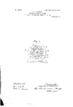
I will describe my invention morein detail by reference to the accompanying drawings, in which---- Figure l is an end view of a motor built in accordance with my invention. Fig. 2 is a side view thereof. Fig. 3 is a detail view of the same, illustrating eccentric relations between fields-and armature. Fig. 4 is a diagrammatic view of another arrangement of field-coils relative'to the armature. Fig. fiis a perspective view ofv the same, showing a means for rifecting speed control. Fig, 6 is a diagrammaticview of an unsymmetrical arrangement of field-coils, with the polar circle substantially concentric with the circumference of the armature. Fig. 7 is a side view of-another arrangement, in which a plurality of armatures maybe employed.
Like characters of reference indicate like parts throughout the views.
Referring now. particularly to Figs. 1, 2, and 3, I have shown an armature 1, provided 1 with any suitable well-known type of induction-motor-armature winding-such, for ini stance,as the squirrel-cage-suitably mounted on a shaft 2, supported in the bearings 3 3. 5 Iinductivelyassociatea fieldframe 4 with i the said armature 1, the said field-frame being provided with any suitable form of inducition-motor winding,a three-phase-drum winds ing consisting of coils 5 5. being shown in this instance. I may intcrpose a sector 6, 7o consisting preferablyoflaminated iron, which sector maybe of any suitable form desired. As will be seen most clearly from Fig". 3, I so relatively associate the armature and field that the axis of the armature does not coincide with the axis of the polar circle that is,
the circle upon which the field-coils are placed.
This eccentric arrangement of the armature relatively to the field-coils enables me to obtain an' armature-speed which is in ex- 80. cess of the speed which would be obtained ac- 4 cording to the law of rotating field devices hereinbeforespecifically set forth. In the present case current is inducedin the armature by one part of the magnetic field which 5 flows in such a direction that it is repelled or attracted by the magnetism due to some other part of the magnetic field, due in this case to polyphase currents. iAsl"- has' been before stated, the sector 6'need not beemployed or 9 may have a different forms i To more clearly'i llustra'te the operation of 'my improved device, I may liken the rotating field as created, for instance, by the drumwinding of Fig. 3 to an internal friction-pulley. The armature may also be likened to a pulley of smaller diameter than the diameter of the rotating field-core. If it be now assumed that the larger pulley engages on its internal surface the exteriorsurface of the 00 smaller pulley, which is likened to' the arma" ture, the smaller pulley or armature will revolve with a given angular velocity.- Ifnow the diameter of the inner pulley or armature be increased or decreased, its angular velocity will be respectively decreased or increased. The action of the rotatingrlield upon the armature is similar in its effect, and the theoretical limiting-speed at which the armature will-rcvolve is dependent upon the difiercncein size between the diameter of. the armature and the diameter of the circular core of the fieldwindings, as well as upon the -relative displacement between the armature-axis and the axis of the rotating-field. it will thus beelear YIO that the speed of the armature shown in Fig.
3 is in excess of the speed ot'synchronismof the rotating field, which latter circumstance would only arise if the armature or. smaller pulley wereof the same size as the internal 4 pulley above referred to, which represents the rotating field. I
In Figs. 4 and 5 I have shown another adaptation of the invention, the iicld'windings being disposed upon a polar circle whose diameter is considerably in excess of thediame ter of the armature, the whole armature, however, not being i'nclosed by field-windings, the said field-windings being in this instance disposed only upon an arc of the polar circle. 3
In this instance I have shown anarmatu re 1,
provided with short-circuited coils 7, the armature in this instance being a-ring-armatu re, field-magnets 8 being shown as disposed about an arc of. the polar circle. In this instance three-phase currents are applied to the termihals A, B, and Got the field-poles, their connection being in this instance in star or Y fashion. The connections between short-circuited armature-coils (shown at? 17 may be omitted or the individual coils need not-be. short-circuited; but these or similarly-con ceived connections may serve the function of short-circuiting'the coils through each other.
in any manner desired; 1 have. shown the field-poles 8 as mounted in a field-frame 9 in Fig; the said field-frame being adjustable transversely with respect to the armature through the agency of guides 10,'a screw 11, and screw-post 12. They armature 1 is preferably mounted in bearings 13, the said bearings being stationary 'relative to the guides 10, so that a displacement between the centers of the armature circumference and the polar circle may readily be effected, thereby securing a change in the theoretical maximum limit of 'speed at which the armature is adapted to operate. 1 'Ihave'in'this instance shown the p'oles'in duplicate upon opposite sid s of the armature, any suitable construction of poles,
' totem-when arranged in the above fashionefiecting thejfsameresiilt, as will be understood: An, "unsymmetrical arrangement of someg-instancesgivin'g the-strongcrtorqne.
l wiudings. necessary to accomplish the wise by, maintaining ,the'polar circle concensame object may,"however, be effected liketric with respect to the armature andchanging-the relative distribution of the field-windings about the field-frame, so that the coils will be broadly spread at some points or congested at others, the broadly-spread coils in v The field-sectiolis to which current is supplied atthe terminals A, B, and C are provided with windings having portions in which a given number of turns is arranged to cover certain sectors and portions on which an equalor unequal number of turns is arranged to cover a larger sector, the said portions being prefer ably-in series and serving tocreate difierent magnetic conditions about the armature-circhmference.
- duplicated Such an arrangement is shown in Fig. 6, the arrangement, however, being upon each half of the armature, although one-half would be s'uflicient normally to operate the same.
In Fig 1 have shown my improved fieldframeas adapted to include a plurality of suit able armatures, the said armaturcs being ea-' pable of supplying power independently or of being geared together, as indicated in the figure, and supplying power to one shaft. The windings of thefield-frame in this instance may be of any of the above-mentioned types, the said windings being inclosed within the frame 9, speed control beingefiected by varying the relative magnetic distribution set up by the said ifield-windings t'or instance, either by varyingthe nelative distribution'of the windings themselves or by varyingfthe current distribution thereon. l have shown magnetic pole-pieces 14 14 as' integrally united with the field-frame and a cent'rallylocated magnetic core 15' placed centrally withrespect thereto, which serves to reduce the mag' netizing-current required in the operationof the machine. These magnetic cores may, however, be omitted, it" desired, or may be given a different form. I have in this instance shown a gear-wheel 16" mounted upon a centrally-located shaft, which is. geared to all of the armatures and through which all of the armatures may transmit power to the" central driving-shaft,-or either one of the ar- 0 mature-driving shafts'may be used as the main driving-shaft, if desired. I have shown bearing-supports 17 for the armature-shafts.
My construction is not limited to the use armatures; but armatures either wholly or in part of electrically -conducting materials. either with or without constrained paths for the induced currents, may be'made a part of motive devices embodying my invention.
1 have herein shown and particularly described the preferred embodimentof my in-' of motors witlfsquirrel-cage or other wound vcntion; but I do not wish to limit myself to the precise arrangement and construction shown, as many modifications thereof may readity be made without departing from the spirit thereof. 7
What I therefor desire to claim is--- 1. In an induction-motor, the combination. with an' armature, of means for causingsaid armature to rotate at a theoretical maximum limiting speed differing from the ratio of alte'rn'ations oi the current per minute to the number of magnetic poles in the field, said means comprising windings for creating a rotating field, unsymmetrically disposed about said armature, substantially as described.
2. in an inductiommotor, the combination means comprising windings for creating a rotating field, eecentrically disposed about said armature, substantially as described.
c 4. In an induction-motor, 'the combinat on .with an armature, of means for causing said segue theoretical limiting speed of the motor may 65 armature to rotate at a theoretical maximum I limitin'gspeed greater than the ratio of alternations'of the current per minute to the number of magnetic poles in the field, said means with a rotating field, said means. comprising windings for creating a rotating field eccentrically or unsymmetrically disposed, or both, with respect to the said armature, substantially as described.
6. In an induction-motor, the combination with an armature provided with Constrained paths for induced electric currents, of meansfor causing said armature to rotate at a limiting speed either in excess or below thespeed 'of synchronism with a rotating field, said means'comprising windings for creating a rotating field eccentrically' or 'unsymmetricallyI disposed, or both, with respect to thcsaid armature, substantially as described.
7. In an induction-motor, the combination with an armature provided-with constrained paths for induced electric currents, of means" for causing said armature to rotate ata theoreticalmsximum limiting speed differingfrom' the ratio of alternations of the current per minute to the number of magnetic poles in.
the field, said means'comprising windings for creating a rotating field, unsymmetricaliy disposed about said armature, substantially as described- V 8. In an induction-motor, the combination with an armature provided with constrained paths for. induced electric currents, of means for causing said armature to rotate at a theoretical maximum limiting speed differing from the ratio of-alternations of the current per minute to the number of magnetic poles in the field, said means comprising windings for creatinga rotating field, eccentricallydisposed about said armature,
scribed. v I
9. In an induction-motor, the combination substantially as die with an armature provided with paths for in I duced currents, of means -for causing ,said armature to rotate at a theoretical limiting speed differing from thespeed of synchronis'm with" a rotating field, said meanscomprising windings for creating a rotating field, eecentrically or unsymmetrically disposed, or both, with respect to the said armature, substantially as described.
10. In an induction motor with primary and secondary windings in eccentric or unsymmetrical relations, or both, toward each other, means for varying the relative eccentricity or d ssymmetry, or both, whereby the be varied, substantially as described.
11. In an induction-motor with armature and fieldsin eccentric or unsymmetrical relations to each other, or both, meansler varying the relative eccentricity or dissymmetry, or both, whereby the theoretical limiting speed of the motor may be varied, substantially as described. f
12, in an induction-motor, the combination with an armature provided with constrained paths for induced currents, of means forbaus- 'ing said armature to rotate at a theoretical limiting speed differing from the speed of synchronism with a rotating field, said means. comprising windings for creating a' rotating field, eccentrically or unsymmetrically disposed, or both, with respect to the said armature, substantially as described.
13. In an induction-motor, the combination with an armature provided with windings, of 8 5 primary or field windings unsymmefrically disposed withrespecttosaid armature-windings for causing armature to rotate at a theoreticahmaximum limiting speed differing from. the ratio of alternationssof the current per minute to the nimiber of magnetic. poles in the field,"substantially as'described.
,14. vIn an i nriuction -m ot ir,the combination with an armature-provided with windings, of primary .or field i windings".eccentrically dis- 9 5 posed withrespc'ct tosaid armature-windings for causing said armature to; rotate at a theo jretical maximum limiting speed differing fr'onij the ratio of alternationlsof-thc current per mi ute to the number of} magnetic poles in -the field, substantially'as' described. v i
15. In an induction-motor, the combination. with an armaturcprovidcd with windings, of primary or field "windings, eccentrically disposed with respect to said armature-windings for causing said armatu re torotate at a theo retical maximum limiting speed differing from the ratio of aiternat onsof the current per min-.
ute to the number of magnetic poles in the field, and means for varying the said eccentricity, substantially as described.
16. in an induction-motngthecombination with an armature provided with windings, of primary or field windingsunsymmetrically disposed with respect to said armature-windings for causing said armature to rotateat a theoretical maximum limiting speed differing from the ratioof-alternations of the current per minute to the number of magnetic poles in the field, and means for varying said dissymmetry, substantially as described. 17. In an induction-motor, the combinatien with an armature receiving its current by induction, of means for causing the armature to rotateat a limitin speed either in excess or below the speed c s chronism with a rotating'field. causing sai rotation of the armature, substantially as described, 7
"AHA".
. .18. hi an imluction-niot'or, the combina tion with an armature receiving its current by induction, of field-windings for producing a rotating field for causing said armature to rotate at a theoretical maximum limiting speed difieringfrom the speed of synchronism of the said rotating lield, substantially as described. 1
l9. lu an induction-motor, the combination with an armature receiving its current by induction, of' means for causing the armature to rotate at a .theoretical maximum limiting speed which is in excess or below the speed of synehronism with a shifting field causing said rotation, substantially as described. i
20. In an induction-motor, the combination with an armature receiving its current by induction, of field-windings for producing a shifting field for causing said armature tg rotate at a theoretical magg' nuinlimiting speed differing from the" s as (1 lot synchronism of the said shifting fiel siibjstantiallyas described.
2.1. Inan induction-motor, the combination with an armature, of means for causing said armature to rotate at rotating field' eecentrieally disposed with re heoretical maxi mum limiting speed greater than the ratioof number-of magnetie' polesfin' he field, sai'd means comprising windings for creating a '1900 alternationsof the eurrentp minutetothe field-windings for creating a shifting field,
and means whereby said field-windingsare adapted to cause a rotation of sa d armature whose limiting speed is either in excess or be.-
low the speed of synchronism with said shifting field, substantially as described:
24. The combination withan armature, of field-windings for creating a rotating field,
and means whereby said fieldwindings: are
adapted to cause a rotation of said armature who's e limiting speedis either in excess or below-the s eed of synehronism with said rotating'fiel substantially. as deseribed."
In w tness whereof I hereunto subscribe my name "this- 24th day of -Eebruary', A. D.
.. QJACKS'QN.
Priority Applications (1)
| Application Number | Priority Date | Filing Date | Title |
|---|---|---|---|
| US24273400A US802452A (en) | 1900-03-08 | 1900-03-08 | Induction-motor device. |
Applications Claiming Priority (1)
| Application Number | Priority Date | Filing Date | Title |
|---|---|---|---|
| US24273400A US802452A (en) | 1900-03-08 | 1900-03-08 | Induction-motor device. |
Publications (1)
| Publication Number | Publication Date |
|---|---|
| US802452A true US802452A (en) | 1905-10-24 |
Family
ID=2870935
Family Applications (1)
| Application Number | Title | Priority Date | Filing Date |
|---|---|---|---|
| US24273400A Expired - Lifetime US802452A (en) | 1900-03-08 | 1900-03-08 | Induction-motor device. |
Country Status (1)
| Country | Link |
|---|---|
| US (1) | US802452A (en) |
-
1900
- 1900-03-08 US US24273400A patent/US802452A/en not_active Expired - Lifetime
Similar Documents
| Publication | Publication Date | Title |
|---|---|---|
| US4035680A (en) | Variable reluctance motor | |
| US2108662A (en) | Inductor dynamo-electric machine | |
| US4260944A (en) | Pulsating signal generator for the production of polyphase voltages of interference | |
| US2120109A (en) | Inductor dynamo-electric machine | |
| US2790098A (en) | Polyphase synchronous machine | |
| US1526613A (en) | Dynamo-electric machine | |
| US1597453A (en) | Alternator | |
| US802452A (en) | Induction-motor device. | |
| US1612330A (en) | Pulsating-torque machine | |
| US2675494A (en) | Adjustable pole pitch dynamoelectric machinery | |
| US2749459A (en) | Plural unit induction motor | |
| US1934060A (en) | Condenser motor | |
| US1491441A (en) | High-speed alternating-current dynamo-electric machine | |
| US2054678A (en) | Direct-current motor-inductor alternator | |
| US1158243A (en) | Transmission apparatus. | |
| US3060336A (en) | Electric motor | |
| US1298375A (en) | Electromagnetic power-transmitting apparatus. | |
| US2563577A (en) | Dtnamoelectmc apparatus | |
| US1673673A (en) | Electrical converter | |
| US1189296A (en) | Variable-speed motor. | |
| US545554A (en) | Alternating-current generator or motor | |
| US853107A (en) | Method of operating electric motors. | |
| US630419A (en) | Alternating-current motor. | |
| US591267A (en) | Alternating-current generator | |
| US688805A (en) | Alternating-current motor. |