US802422A - Space telegraphy. - Google Patents
Space telegraphy. Download PDFInfo
- Publication number
- US802422A US802422A US258039A US1905258039A US802422A US 802422 A US802422 A US 802422A US 258039 A US258039 A US 258039A US 1905258039 A US1905258039 A US 1905258039A US 802422 A US802422 A US 802422A
- Authority
- US
- United States
- Prior art keywords
- receiving
- circuit
- conductor
- elevated
- resonant
- Prior art date
- Legal status (The legal status is an assumption and is not a legal conclusion. Google has not performed a legal analysis and makes no representation as to the accuracy of the status listed.)
- Expired - Lifetime
Links
- 239000004020 conductor Substances 0.000 description 68
- 238000004804 winding Methods 0.000 description 11
- 230000002085 persistent effect Effects 0.000 description 7
- 230000010355 oscillation Effects 0.000 description 6
- 241001641735 Cygnus cygnus Species 0.000 description 1
- 230000000694 effects Effects 0.000 description 1
- 230000033458 reproduction Effects 0.000 description 1
Images
Classifications
-
- H—ELECTRICITY
- H04—ELECTRIC COMMUNICATION TECHNIQUE
- H04B—TRANSMISSION
- H04B1/00—Details of transmission systems, not covered by a single one of groups H04B3/00 - H04B13/00; Details of transmission systems not characterised by the medium used for transmission
- H04B1/06—Receivers
- H04B1/16—Circuits
- H04B1/18—Input circuits, e.g. for coupling to an antenna or a transmission line
Definitions
- This invention relates to the art of transmitting intelligence from one station to another by means of electromagnetic waves without the use of wires to guide the waves to their destination; and it relates more particularly to systems for receiving signals transmitted by such waves.
- the object of the present invention is to so adjust the elevated conductor system of a wireless or space telegraph receiving station relative to an associated tuned or resonant receiving circuit or circuits that, first, a persistent train of electromagnetic waves of a predetermined frequency impinging upon the elevated conductor shall cause the associated circuit or circuits to respond energetically; that, second, a persistent train of electromagnetic waves of frequency other than said predetermined frequency impinging upon the elevated conductor shall cause the associated tuned or resonant circuit or circuits to respond but feebly; and
- the first and second objects of this invention may be attained by giving the elevated receiving conductor system a pronounced fundamental of a frequency which is the same as that to which the associated tuned or resonant receiving circuit or circuits is attuned.
- the first and second objects of this invention may therefore be attained by placing a suitable ind uctance or capacity in the elevated con ductor near its connection to earth, if it be an earthed elevated conductor, or at the center of a receiving conductor, if it be an unearthed conductor, as thereby the receiving conductor will be given a pronounced and predetermined fundamental, much as a stretched string may be given a predetermined and more pronounced fundamental by the addition of a suitable load at its center.
- the loading inductance or capacity added be made such as to give the elevated conductor system a fundamental whose frequency is the same as that of the associated tuned or resonant receivingcircuit or circuits, the first and second objects of the invention will be realized.
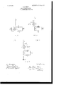
- FIGs. 1, 2, and 3 illustrate space telegraph receiving systems embodying the present invention.
- V is an elevated receiving conductor.
- E is an earth connection.
- M is a transformer whose primary and secondary windings are L and 1'2.
- M is a transformer whose primary and secondary windings are 1'1 and 1's.
- C C C1 are condensers.
- L is an auxiliary inductance coil.
- L1 is an inductance coil.
- K is a bolometer or other suitable wave detector.
- the means whereby natural rates of vibration are given to the elevated conductor system, which natural rates are made difierent from that of the associated resonant receiving circuit is the circuit C Iz inductively associated with said elevated conductor system by means of the inductance coil L1 in Fig. 1, the primary winding L of the transformer M in Fig. 2, or the primary winding IQ of the transformer M in Fig. 3.
- the circuit C 1'2 employed for giving the elevated conductor system natural rates of vibration different from that to which the associated resonant receiving circuit is responsive will, in combination with the coils L1, L, or T1 and by its reaction thereon, present a definite capacity or inductance reactance for a predetermined frequency of impressed force, and said reactance will be dilferentfor different frequencies ofim pressed force.
- the reactance of the elevated conductor per 86 is a capacity reactance and therefore for such waves the circuit C Ig may be so proportioned as to present, in combination with its associated primary winding and by its reaction thereon, an inductance reactance equivalent to that which would be given by a loading coil adapted to make the fundamental of the elevatedconductor system of a frequency equal to that of the waves to be received.
- the reactance offered by the elevated conductor system to the electrical oscillations developed therein by a persistent train of simple harmonic waves of such frequency is therefore Zero.
- the reactance of the elevated conductor parse is an inductance reactance and therefore for such waves the circuit C 1'2 may be so proportioned as to present, in combination with its associated primary Winding and by its reaction thereon, a capacity reactance equivalent to that which would be given by a loading condenser adapted to make the fundamental of the elevated conductor system equal to the frequency of the waves to be received.
- the reactance offered by the elevated conductor system to the electrical oscillations developed therein by a persistent train of simple harmonic waves of such frequency is therefore Zero.
- resonant receiving circuits each attuned to the frequency of the waves the energy of which is to be received.
- These resonant receiving circuits are preferably constructed according to the specifications of my Letters Patent Nos. 767,989 and 767,990, August 16, 1904, and each is preferably conductivelyconnected to its elevated receiving conductor in such manner that the self energy of each of the conductively connected circuits of a system is great as compared to the mutual energy of each circuit with respect to the other circuits of such system. This is accomplished in Figs. 1 and3 by making the inductance of the coil L large compared to the inductance of the coil L1, and in Fig. 2, by making the capacity of the condenser C small compared to the capacity of the condenser C1.
- I claim 1 As a means for preventing a resonant receiving circuit of a space telegraph receiving system from responding to extraneous electrical forces of a frequency to which said resonant receiving circuit is not attuned or to abrupt or impulsive electrical forces, a resonant receiving circuit attuned to the frequency of the waves the energy of which is to be received, an elevated receiving conductor system conductively connected with said resonant receiving circuit, and a circuit, containing a condenser, inductively associated with said elevated receiving conductor system and so proportioned as to give the elevated receiving conductor system natural rates of vibration different from that of the associated resonant receiving circuit.
- a resonant receiving circuit attuned to the frequency of the waves the energy of which is to be received, a receiving conductor conductively connected with said resonant receiving circuit, and a circuit, containing capacity and inductance, inductively associated with said receiving conductor.
- a receiving circuit attuned by capacity and inductance to the frequency of the waves the energy of which is to be received, a receiving conductor conductively connected with said receiving circuit, and a circuit, containing capacity and inductance, inductively associated with said receiving conductor.
- a receiving circuit attuned by capacity and inductance to the frequency of the waves the energy of which is to be received, a receivin conductor conductively connected with said receiving circuit, the primary winding of a transformer serially connected in said receiving conductor, and a circuit, containing capacity and inductance, inductively associated with said primary winding.
- a resonant receiving circuit attuned to the frequency of the waves the energy of which is to be received, an elevated receiving conductor conductively connected thereto, means whereby the mutual energy of the resonant circuit with the elevated conductor is made small compared to the self energy of the resonant circuit, and a circuit, containing a condenser, inductively associated with said receiving conductor.
- av resonant receiving circuit attuned to the frequency of the waves the energy of which is to be received and including an inductance coil, an elevated receiving conductor conductively connected to said coil, a second coil in said resonant circuit of inductance great compared to the inductance of the first menr I I tioned coil, and a circuit, containing a condenser, inductively associated with said receiving conductor.
- a resonant receiving circuit attuned to the frequency of the waves the energy of which is to be received and including an inductance coil, an elevated receiving conductor conductively connected to said coil, a second coil in said resonant circuit of inductance great compared to the inductance of the first mentioned coil, and a circuit, containing capacity and inductance, inductively associated with said receiving conductor.
- a receiving circuit attuned to the frequency of the waves the energy of which is to be received and including an inductance coil, an elevated receiving conductor conductively connected to said coil, the primary winding of the transformer serially connected in said receiving conductor, and a circuit, containing capacity and inductance, inductively associated with said primary winding.
- a resonant receiving circuit attuned to the frequency of the waves the energy of which is to be received; a receiving conductor conductively connected thereto and adapted to present for impressed forces of said frequency an inductance reactance; and a circuit, containing capacity and inductance, inductively associated with the receiving conductor system and so designed as to present, by its reaction on said receiving conductor system for impressed forces of said frequency, a capacity reactance equivalent to that which would be presented by a loading condenser adapted to make the fundamental of said receiving conductor system of a frequency equal to that of the waves to be received and thereby to balance the inductance reactance of the receiving conductor per se for impressed forces of said frequency.
- a resonant receiving circuit attuned to the frequency of the waves the energy of which is to be received; a receiving conductor conductively connected thereto and adapted to present for impressed forces of said frequency a definite reactance; and a circuit, containing capacity and inductance, inductively associated with the receiving conductor system and so designed as to present, by its reaction on said receiving conductor system for impressed forces of said frequency, a reactance equal and opposite to the reactance of the receiving conductor per se and thereby to balance the reactance of said receiving conductor per se for impressed forces of said frequency.
- a resonant receiving circuit attuned to the frequency of the waves the energy of which is to be received and including an inductance coil, an elevated receiving conductor conductively connected with said coil, means whereby the mutual energy of the resonant circuit with respect to the elevated conductor is made small compared to the self energy of said resonant circuit, and a circuit, containing a condenser, inductively associated with said receiving conductor and so proportioned as to give the elevated conductor system zero reactance for electrical oscillations developed therein by a persistent train of simple harmonic waves of the frequency to which said resonant receiving circuit is attuned.
- a resonant receiving circuit of a space telegraph receiv ing system As a means for preventing a resonant receiving circuit of a space telegraph receiv ing system from responding to extraneous electrical forces of a frequency to which said resonant receiving circuit is not attuned, or to abrupt or impulsive electric forces, and for assisting said resonant circuit to respond to persistent forces of the frequency to which said circuit is attuned, the combination of a resonant receiving circuit attuned to the frequency of the waves the energy of which is to be received, an elevated receiving conductor system conductively connected with said resonant receiving circuit, and a circuit containing a condenser inductively associated with said elevated receiving conductor system and so proportioned that it shall by its reaction on the elevated conductor system cause the elevated conductor system to have zero reactance for electrical oscillations developed therein by a persistent force acting thereon and of the frequency to which said resonant receiving circuit is attuned.
Landscapes
- Engineering & Computer Science (AREA)
- Computer Networks & Wireless Communication (AREA)
- Signal Processing (AREA)
- Train Traffic Observation, Control, And Security (AREA)
Description
No. 802,422. PATENTED OCT. 24, 1905. 3.. 3. $TONE. SPACE TELEGRAPH? APPLICATION FILED APR. 29, 1905.
STATES IlATENT OFFICE.
JOHN STONE STONE, OF CAMBRIDGE, MASSACHUSETTS, ASSIGNOR TO WILLIAM W. SWAN, TRUSTEE, OF BOSTON, MASSACHUSETTS.
SPACE TELEGRAPHY.
Specification of Letters Patent.
Patented Oct. 24, 1905.
Original application filed February 23, 1904, Serial No. 194,649. Divided and this application filed April 29, 1906. Serial No. 258,039.
To all whom it rrtrty concern:
Be it known that I, JOHN S'roNn SroNn, a citizen of the United States, and a resident of Cambridge, in the county of Middlesex and State of lVIassachusetts, have invented a certain new and useful Improvement in Space 'Ielegraphy, of which the following is a specilication.
This invention relates to the art of transmitting intelligence from one station to another by means of electromagnetic waves without the use of wires to guide the waves to their destination; and it relates more particularly to systems for receiving signals transmitted by such waves.
The object of the present invention is to so adjust the elevated conductor system of a wireless or space telegraph receiving station relative to an associated tuned or resonant receiving circuit or circuits that, first, a persistent train of electromagnetic waves of a predetermined frequency impinging upon the elevated conductor shall cause the associated circuit or circuits to respond energetically; that, second, a persistent train of electromagnetic waves of frequency other than said predetermined frequency impinging upon the elevated conductor shall cause the associated tuned or resonant circuit or circuits to respond but feebly; and
that, third, abrupt or impulsive electric forces acting upon the elevated conductor shall likewise produce but feeble response in the associated tuned or resonant circuit or circuits.
The first and second objects of this invention may be attained by giving the elevated receiving conductor system a pronounced fundamental of a frequency which is the same as that to which the associated tuned or resonant receiving circuit or circuits is attuned.
The first and second objects of this invention may therefore be attained by placing a suitable ind uctance or capacity in the elevated con ductor near its connection to earth, if it be an earthed elevated conductor, or at the center of a receiving conductor, if it be an unearthed conductor, as thereby the receiving conductor will be given a pronounced and predetermined fundamental, much as a stretched string may be given a predetermined and more pronounced fundamental by the addition of a suitable load at its center.
If, therefore, the loading inductance or capacity added be made such as to give the elevated conductor system a fundamental whose frequency is the same as that of the associated tuned or resonant receivingcircuit or circuits, the first and second objects of the invention will be realized.
But this simple device is not sufficient to accomplish the third object of the present invention, and for that purpose it is necessary to give the elevated conductor natural periods of vibration whose frequencies are different from that to which the associated tuned or resonant receiving circuit or circuits is attuned, and this in turn I accomplish by giving the elevated conductor system a plurality of degrees of freedom by any one of a variety of means.
In other words, I accomplish the third object of this invention by employing an elevated conductor system having natural rates of vibration different from the frequency of the waves the energy of which is to be received, and consequently different from the frequency to which the associated tuned or resonant receiving circuit or circuits is attuned.
The invention may best be understood by having reference to the drawings which accompany and form a part of this specification and which illustrate diagrammatically arrangements of apparatus and circuits whereby the present invention may conveniently be carried into effect.
Figs. 1, 2, and 3, illustrate space telegraph receiving systems embodying the present invention.
In the figures,
V is an elevated receiving conductor.
E is an earth connection.
M is a transformer whose primary and secondary windings are L and 1'2.
M is a transformer whose primary and secondary windings are 1'1 and 1's.
C C C1 are condensers.
L is an auxiliary inductance coil.
L1 is an inductance coil. K is a bolometer or other suitable wave detector.
This application is a division of my application Serial No. 194,649 liled Feby. 23, 1904:, in which I have broadly claimed the invention disclosed herein and in which I have specifically claimed those embodiments of the broad invention which are illustrated in Figs. 1, 2, 5 and 6 thereof, in which figures the resonant receivingcircuit is inductively associated with the elevated receiving conductor. Therefore, in the present application, I confine my claims to those embodiments of the broad invention which areillustrated in Figs. 3, 4, and 7 of the parent application, or the electrical equivalents thereof, in which figures the elevated receiving conductor is conductively connected to the resonant receiving circuit across the terminals of an inductance coil or a condenser.
In Figs. 1, 2, and 3 of the present case, which figures are reproductions of the aforesaid figures 3, 4, and 7, respectively, of the parent application, the means whereby natural rates of vibration are given to the elevated conductor system, which natural rates are made difierent from that of the associated resonant receiving circuit, is the circuit C Iz inductively associated with said elevated conductor system by means of the inductance coil L1 in Fig. 1, the primary winding L of the transformer M in Fig. 2, or the primary winding IQ of the transformer M in Fig. 3.
As more fully explained in my application Serial No. 194,649, the circuit C 1'2 employed for giving the elevated conductor system natural rates of vibration different from that to which the associated resonant receiving circuit is responsive will, in combination with the coils L1, L, or T1 and by its reaction thereon, present a definite capacity or inductance reactance for a predetermined frequency of impressed force, and said reactance will be dilferentfor different frequencies ofim pressed force.
hen the waves to be received are longer than those natural to the elevated conductor per 86, the reactance of the elevated conductor per 86 is a capacity reactance and therefore for such waves the circuit C Ig may be so proportioned as to present, in combination with its associated primary winding and by its reaction thereon, an inductance reactance equivalent to that which would be given by a loading coil adapted to make the fundamental of the elevatedconductor system of a frequency equal to that of the waves to be received. The reactance offered by the elevated conductor system to the electrical oscillations developed therein by a persistent train of simple harmonic waves of such frequency is therefore Zero.
hen the waves to be received are shorter than those natural to the elevated conductor per se and not less than one half the length of those natural to the elevated conductorperse, the reactance of the elevated conductor parse is an inductance reactance and therefore for such waves the circuit C 1'2 may be so proportioned as to present, in combination with its associated primary Winding and by its reaction thereon, a capacity reactance equivalent to that which would be given by a loading condenser adapted to make the fundamental of the elevated conductor system equal to the frequency of the waves to be received. Here again the reactance offered by the elevated conductor system to the electrical oscillations developed therein by a persistent train of simple harmonic waves of such frequency is therefore Zero.
I find by experience that when such proportions are given to the constants of the inductively related circuit C 1 2 that, in combination with its associated primary winding and by its reaction thereon, it will present for the frequency of the waves to be received and to which the resonant receiving circuit is attuned, a reactance equal and opposite to the reactance of the elevated conductor per sag-the elevated conductor system in responding to electrical impulses of frequencies to which said resonant receiving circuit is not attuned, orto abrupt or impulsive electrical forces, has developed in it natural oscillations of frequencies ill adapted to cause a response of the associated resonant receiving circuit, because the frequencies of said natural oscillations are different from the frequencies to which said resonant circuit is attuned.
A more complete exposition of the general principles upon which the present invention is founded has been set forth in my hereinbefore mentioned application gerial No. 194,649 and in my Letters Patent No. 767, 994, dated August 16, 1904, to which reference may be had.
The circuits 0 L1 L K of Figs. 1 and 3,
and the circuit C1 C K L of Fig. 2, are resonant receiving circuits, each attuned to the frequency of the waves the energy of which is to be received. These resonant receiving circuits are preferably constructed according to the specifications of my Letters Patent Nos. 767,989 and 767,990, August 16, 1904, and each is preferably conductivelyconnected to its elevated receiving conductor in such manner that the self energy of each of the conductively connected circuits of a system is great as compared to the mutual energy of each circuit with respect to the other circuits of such system. This is accomplished in Figs. 1 and3 by making the inductance of the coil L large compared to the inductance of the coil L1, and in Fig. 2, by making the capacity of the condenser C small compared to the capacity of the condenser C1.
It is obvious that in Figs. 2 and 3 the primary coil 11 or IE may be situated below the condenser C1 or the coil L1, respectively, as well as in the positions shown in the drawings, and that many other changes maybe made in the relative arrangement of the apparatus herein specifically described without departing from the spirit of my invention.
I claim 1. As a means for preventing a resonant receiving circuit of a space telegraph receiving system from responding to extraneous electrical forces of a frequency to which said resonant receiving circuit is not attuned or to abrupt or impulsive electrical forces, a resonant receiving circuit attuned to the frequency of the waves the energy of which is to be received, an elevated receiving conductor system conductively connected with said resonant receiving circuit, and a circuit, containing a condenser, inductively associated with said elevated receiving conductor system and so proportioned as to give the elevated receiving conductor system natural rates of vibration different from that of the associated resonant receiving circuit.
2. In a space telegraph receiving system, aresonant receiving circuit attuned to the frequency of the waves the energy of which is to be received, a receiving conductor conductively connected with said resonant receiving circuit, and a circuit, containing a condenser, inductively associated with said receiving conductor.
3. In a space telegraph receiving system,
a resonant receiving circuit attuned to the frequency of the waves the energy of which is to be received, a receiving conductor conductively connected with said resonant receiving circuit, and a circuit, containing capacity and inductance, inductively associated with said receiving conductor.
4. In a space telegraph receiving system, a receiving circuit attuned by capacity and inductance to the frequency of the waves the energy of which is to be received, a receiving conductor conductively connected with said receiving circuit, and a circuit, containing capacity and inductance, inductively associated with said receiving conductor.
5. In a space telegraph receiving system, a receiving circuit attuned by capacity and inductance to the frequency of the waves the energy of which is to be received, a receivin conductor conductively connected with said receiving circuit, the primary winding of a transformer serially connected in said receiving conductor, and a circuit, containing capacity and inductance, inductively associated with said primary winding.
6. In a space telegraph receiving system, a resonant receiving circuit attuned to the frequency of the waves the energy of which is to be received, an elevated receiving conductor conductively connected thereto, means whereby the mutual energy of the resonant circuit with the elevated conductor is made small compared to the self energy of the resonant circuit, and a circuit, containing a condenser, inductively associated with said receiving conductor.
7. In a space telegraph receiving system, av resonant receiving circuit attuned to the frequency of the waves the energy of which is to be received and including an inductance coil, an elevated receiving conductor conductively connected to said coil, a second coil in said resonant circuit of inductance great compared to the inductance of the first menr I I tioned coil, and a circuit, containing a condenser, inductively associated with said receiving conductor.
8. In a space telegraph receiving system, a resonant receiving circuit attuned to the frequency of the waves the energy of which is to be received and including an inductance coil, an elevated receiving conductor conductively connected to said coil, a second coil in said resonant circuit of inductance great compared to the inductance of the first mentioned coil, and a circuit, containing capacity and inductance, inductively associated with said receiving conductor.
9. In a space telegraph receiving system, a receiving circuit attuned to the frequency of the waves the energy of which is to be received and including an inductance coil, an elevated receiving conductor conductively connected to said coil, the primary winding of the transformer serially connected in said receiving conductor, and a circuit, containing capacity and inductance, inductively associated with said primary winding.
10. In a space telegraph receiving system, a resonant receiving circuit attuned to the frequency of the waves the energy of which is to be received; a receiving conductor conductively connected thereto and adapted to present for impressed forces of said frequency an inductance reactance; and a circuit, containing capacity and inductance, inductively associated with the receiving conductor system and so designed as to present, by its reaction on said receiving conductor system for impressed forces of said frequency, a capacity reactance equivalent to that which would be presented by a loading condenser adapted to make the fundamental of said receiving conductor system of a frequency equal to that of the waves to be received and thereby to balance the inductance reactance of the receiving conductor per se for impressed forces of said frequency.
11. In a space telegraph receiving system, a resonant receiving circuit attuned to the frequency of the waves the energy of which is to be received; a receiving conductor conductively connected thereto and adapted to present for impressed forces of said frequency a definite reactance; and a circuit, containing capacity and inductance, inductively associated with the receiving conductor system and so designed as to present, by its reaction on said receiving conductor system for impressed forces of said frequency, a reactance equal and opposite to the reactance of the receiving conductor per se and thereby to balance the reactance of said receiving conductor per se for impressed forces of said frequency.
12. In a space telegraph receiving system, a resonant receiving circuit attuned to the frequency of the waves the energy of which is to be received and including an inductance coil, an elevated receiving conductor conductively connected with said coil, means whereby the mutual energy of the resonant circuit with respect to the elevated conductor is made small compared to the self energy of said resonant circuit, and a circuit, containing a condenser, inductively associated with said receiving conductor and so proportioned as to give the elevated conductor system zero reactance for electrical oscillations developed therein by a persistent train of simple harmonic waves of the frequency to which said resonant receiving circuit is attuned.
134 As a means for preventing a resonant receiving circuit of a space telegraph receiv ing system from responding to extraneous electrical forces of a frequency to which said resonant receiving circuit is not attuned, or to abrupt or impulsive electric forces, and for assisting said resonant circuit to respond to persistent forces of the frequency to which said circuit is attuned, the combination of a resonant receiving circuit attuned to the frequency of the waves the energy of which is to be received, an elevated receiving conductor system conductively connected with said resonant receiving circuit, and a circuit containing a condenser inductively associated with said elevated receiving conductor system and so proportioned that it shall by its reaction on the elevated conductor system cause the elevated conductor system to have zero reactance for electrical oscillations developed therein by a persistent force acting thereon and of the frequency to which said resonant receiving circuit is attuned.
In testimony whereof I have hereunto subscribed my name this 28th day of April, 1905.
JOHN STONE STONE.
Witnesses:
BRAINERD T. JUDKINS, G. ADELAIDE HIGGINS.
Priority Applications (1)
| Application Number | Priority Date | Filing Date | Title |
|---|---|---|---|
| US258039A US802422A (en) | 1904-02-23 | 1905-04-29 | Space telegraphy. |
Applications Claiming Priority (2)
| Application Number | Priority Date | Filing Date | Title |
|---|---|---|---|
| US19464904A US802417A (en) | 1904-02-23 | 1904-02-23 | Space telegraphy. |
| US258039A US802422A (en) | 1904-02-23 | 1905-04-29 | Space telegraphy. |
Publications (1)
| Publication Number | Publication Date |
|---|---|
| US802422A true US802422A (en) | 1905-10-24 |
Family
ID=2870905
Family Applications (1)
| Application Number | Title | Priority Date | Filing Date |
|---|---|---|---|
| US258039A Expired - Lifetime US802422A (en) | 1904-02-23 | 1905-04-29 | Space telegraphy. |
Country Status (1)
| Country | Link |
|---|---|
| US (1) | US802422A (en) |
-
1905
- 1905-04-29 US US258039A patent/US802422A/en not_active Expired - Lifetime
Similar Documents
| Publication | Publication Date | Title |
|---|---|---|
| US802422A (en) | Space telegraphy. | |
| US802423A (en) | Space telegraphy. | |
| US802417A (en) | Space telegraphy. | |
| US2013140A (en) | Translating circuit | |
| US802420A (en) | Space telegraphy. | |
| US1758940A (en) | Means for separating undesired from desired electric currents | |
| US1703171A (en) | Electric-wave filter | |
| US1974184A (en) | Radio apparatus | |
| US767994A (en) | Space telegraphy. | |
| US802430A (en) | Space telegraphy. | |
| US730246A (en) | Space telegraphy. | |
| US767995A (en) | Space telegraphy. | |
| US802421A (en) | Space telegraphy. | |
| US767978A (en) | Space telegraphy. | |
| US2057640A (en) | Radio communication system | |
| US2005388A (en) | Wireless apparatus | |
| US876165A (en) | Wireless telegraph transmitting system. | |
| US2054645A (en) | Antenna system | |
| US802425A (en) | Space telegraphy. | |
| US1590635A (en) | Radio system | |
| US1818157A (en) | Radio receiving circuits | |
| US2219175A (en) | Television intermediate frequency separation circuit | |
| US802426A (en) | Space telegraphy. | |
| US1344275A (en) | Method of and apparatus for electrical communication | |
| US1156677A (en) | Apparatus for the transmission of energy by electric oscillation. |