US7992933B2 - Integrated vehicle seat with active head restraint system - Google Patents
Integrated vehicle seat with active head restraint system Download PDFInfo
- Publication number
- US7992933B2 US7992933B2 US11/766,439 US76643907A US7992933B2 US 7992933 B2 US7992933 B2 US 7992933B2 US 76643907 A US76643907 A US 76643907A US 7992933 B2 US7992933 B2 US 7992933B2
- Authority
- US
- United States
- Prior art keywords
- head restraint
- frame
- linkage
- seat back
- extended position
- Prior art date
- Legal status (The legal status is an assumption and is not a legal conclusion. Google has not performed a legal analysis and makes no representation as to the accuracy of the status listed.)
- Expired - Fee Related
Links
Images


Classifications
-
- B—PERFORMING OPERATIONS; TRANSPORTING
- B60—VEHICLES IN GENERAL
- B60N—SEATS SPECIALLY ADAPTED FOR VEHICLES; VEHICLE PASSENGER ACCOMMODATION NOT OTHERWISE PROVIDED FOR
- B60N2/00—Seats specially adapted for vehicles; Arrangement or mounting of seats in vehicles
- B60N2/80—Head-rests
- B60N2/888—Head-rests with arrangements for protecting against abnormal g-forces, e.g. by displacement of the head-rest
-
- B—PERFORMING OPERATIONS; TRANSPORTING
- B60—VEHICLES IN GENERAL
- B60N—SEATS SPECIALLY ADAPTED FOR VEHICLES; VEHICLE PASSENGER ACCOMMODATION NOT OTHERWISE PROVIDED FOR
- B60N2/00—Seats specially adapted for vehicles; Arrangement or mounting of seats in vehicles
- B60N2/24—Seats specially adapted for vehicles; Arrangement or mounting of seats in vehicles for particular purposes or particular vehicles
- B60N2/42—Seats specially adapted for vehicles; Arrangement or mounting of seats in vehicles for particular purposes or particular vehicles the seat constructed to protect the occupant from the effect of abnormal g-forces, e.g. crash or safety seats
- B60N2/4207—Seats specially adapted for vehicles; Arrangement or mounting of seats in vehicles for particular purposes or particular vehicles the seat constructed to protect the occupant from the effect of abnormal g-forces, e.g. crash or safety seats characterised by the direction of the g-forces
- B60N2/4214—Seats specially adapted for vehicles; Arrangement or mounting of seats in vehicles for particular purposes or particular vehicles the seat constructed to protect the occupant from the effect of abnormal g-forces, e.g. crash or safety seats characterised by the direction of the g-forces longitudinal
- B60N2/4228—Seats specially adapted for vehicles; Arrangement or mounting of seats in vehicles for particular purposes or particular vehicles the seat constructed to protect the occupant from the effect of abnormal g-forces, e.g. crash or safety seats characterised by the direction of the g-forces longitudinal due to impact coming from the rear
-
- B—PERFORMING OPERATIONS; TRANSPORTING
- B60—VEHICLES IN GENERAL
- B60N—SEATS SPECIALLY ADAPTED FOR VEHICLES; VEHICLE PASSENGER ACCOMMODATION NOT OTHERWISE PROVIDED FOR
- B60N2/00—Seats specially adapted for vehicles; Arrangement or mounting of seats in vehicles
- B60N2/24—Seats specially adapted for vehicles; Arrangement or mounting of seats in vehicles for particular purposes or particular vehicles
- B60N2/42—Seats specially adapted for vehicles; Arrangement or mounting of seats in vehicles for particular purposes or particular vehicles the seat constructed to protect the occupant from the effect of abnormal g-forces, e.g. crash or safety seats
- B60N2/427—Seats or parts thereof displaced during a crash
- B60N2/42772—Seats or parts thereof displaced during a crash characterised by the triggering system
- B60N2/42781—Seats or parts thereof displaced during a crash characterised by the triggering system mechanical triggering
-
- B—PERFORMING OPERATIONS; TRANSPORTING
- B60—VEHICLES IN GENERAL
- B60N—SEATS SPECIALLY ADAPTED FOR VEHICLES; VEHICLE PASSENGER ACCOMMODATION NOT OTHERWISE PROVIDED FOR
- B60N2/00—Seats specially adapted for vehicles; Arrangement or mounting of seats in vehicles
- B60N2/68—Seat frames
-
- B—PERFORMING OPERATIONS; TRANSPORTING
- B60—VEHICLES IN GENERAL
- B60N—SEATS SPECIALLY ADAPTED FOR VEHICLES; VEHICLE PASSENGER ACCOMMODATION NOT OTHERWISE PROVIDED FOR
- B60N2/00—Seats specially adapted for vehicles; Arrangement or mounting of seats in vehicles
- B60N2/68—Seat frames
- B60N2/686—Panel like structures
-
- B—PERFORMING OPERATIONS; TRANSPORTING
- B60—VEHICLES IN GENERAL
- B60N—SEATS SPECIALLY ADAPTED FOR VEHICLES; VEHICLE PASSENGER ACCOMMODATION NOT OTHERWISE PROVIDED FOR
- B60N2/00—Seats specially adapted for vehicles; Arrangement or mounting of seats in vehicles
- B60N2/80—Head-rests
- B60N2/806—Head-rests movable or adjustable
- B60N2/838—Tiltable
-
- B—PERFORMING OPERATIONS; TRANSPORTING
- B60—VEHICLES IN GENERAL
- B60N—SEATS SPECIALLY ADAPTED FOR VEHICLES; VEHICLE PASSENGER ACCOMMODATION NOT OTHERWISE PROVIDED FOR
- B60N2/00—Seats specially adapted for vehicles; Arrangement or mounting of seats in vehicles
- B60N2/80—Head-rests
- B60N2/806—Head-rests movable or adjustable
- B60N2/865—Head-rests movable or adjustable providing a fore-and-aft movement with respect to the occupant's head
Definitions
- Various embodiments of the invention relate to active head restraints for vehicle seats.
- Vehicle seats are provided with moveable head restraints for moving to an impact position in response to a signal or force imparted to the seat before or during an impact condition.
- moveable head restraints for moving to an impact position in response to a signal or force imparted to the seat before or during an impact condition.
- FIG. 1 is a perspective view of an embodiment of a vehicle seat illustrated in a design position
- FIG. 2 is a perspective view of a seat back of the vehicle seat of FIG. 1 illustrated with a head restraint in an extended position;
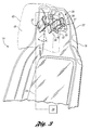
- FIG. 3 is a perspective view of a portion of another embodiment of a seat back of a vehicle seat
- FIG. 4 is a perspective view of the seat back of FIG. 3 with a head restraint in an extended position
- FIG. 5 is a perspective view of another embodiment of the seat back of FIG. 3 ;
- FIG. 6 is a perspective view of an embodiment of a latch mechanism of FIG. 5 ;
- FIG. 7 is a perspective view of another embodiment of a vehicle seat.
- FIG. 8 is a fragmentary side elevation view of a portion of the vehicle seat of FIG. 7 .
- a vehicle seat is illustrated and referenced generally by numeral 10 .
- the vehicle seat includes a seat bottom 12 secured to a floor of an associated vehicle for seating an occupant upon the seat bottom 12 .
- a seat back 14 extends from the seat bottom 12 and is secured relative to the seat bottom 12 for supporting a back of the occupant against the seat back 14 .
- the seat back 14 may pivot relative to the seat bottom 12 to permit ingress and egress to and from a rear seating row and/or to permit an occupant to select a comfortable riding position while sitting in the vehicle seat 10 .
- the seat back 14 includes a frame 16 for providing structural support for the seat back 14 .
- Cushioning 18 is mounted on the frame 16 to support the occupant.
- the cushioning 18 may include foam, padding, bolsters and/or support wires.
- a cover 20 rests over the cushioning 18 to conceal the cushioning 18 .
- Any suitable cushioning 18 and cover 20 such as those known in the art may be mounted on the frame 16 .
- the frame 16 of the seat back 14 is an integrated frame 16 so that the frame 16 collectively includes a head restraint frame portion 22 and a back support frame portion 24 integrated into the frame 16 .
- An integrated frame 16 is commonly used in sports vehicles. With the increase in popularity of sport vehicles, integrated frames 16 also have increased popularity. When covered by the cushioning 18 , the head restraint frame portion 22 supports a head of the occupant and has limited height adjustment relative to the back support portion 24 .
- the back support frame portion 24 when covered by the cushioning 18 as illustrated, supports the back of the occupant and is an integral portion of the frame 16 .
- the head restraint frame portion 22 and the back support frame portion 24 are contoured to be generally flush so that neither the head restraint frame portion 22 nor the back support frame portion 24 covered by cushioning 18 extend farther than the other.
- the back support frame portion 24 is designed to comfortably support the back of the occupant by providing a generally flat surface which is flush with the head restraint frame portion 22 and curved portions on either side of the flat surface. Any suitable design for the back support frame portion 24 is contemplated within the scope of the present invention.
- the head restraint frame portion 22 has a head restraint 42 supported by the head restraint frame portion 22 .
- the head restraint 42 need not be directly mounted to the head restraint frame portion 22 and may be mounted indirectly to the head restraint frame portion 22 in any suitable manner.
- the head restraint 42 may be located in a residing area 44 provided in the head restraint frame portion 22 .
- the head restraint 42 is moveable between two positions and is made of a foam material or any suitable material known in the art. Of course the motion of the head restraint 42 may be linear or nonlinear movement.
- FIG. 1 illustrates a design position for normal driving conditions.
- the head restraint 42 is moveable to an extended position by an active head restraint system 26 for minimizing potential for injury of an occupant.
- the extended position may be any position with any movement of the head restraint 42 when compared to the design position.
- the head restraint 42 when covered by cushioning 18 forms a part of a surface of the head restraint frame portion 22 and is surrounded by the remaining head restraint frame portion 22 .
- active head restraint systems have been limited to vehicle seats with a separate seat back and head restraint which do not have the integrated frame 16 .
- the multiple embodiments of the present invention incorporate the moveable head restraint 42 supported by the head restraint frame portion 22 and the active head restraint system 26 into the integrated frame 16 to make active head restraint systems 26 in integrated frames 16 available.
- the seat back 14 of FIG. 1 is illustrated with the head restraint 42 moved to the extended position from the design position of FIG. 1 .
- the active head restraint system 26 moves the head restraint frame portion 22 from the design position, as in FIG. 1 , to the extended position depicted.
- the active head restraint system 26 helps to minimize whiplash injury to an occupant by extending the head restraint 42 toward the head of the occupant.
- a whiplash injury occurs when the occupant's head is over-extended during an impact condition.
- the seat 10 is accelerated into the occupant, and the back of the occupant moves a distance into the seat back frame portion 24 . Accordingly, the head restraint 42 is moved toward the head of the occupant to support the occupant's head to minimize potential for injury to the occupant.
- the active head restraint system 26 is in the extended position.
- the head restraint 42 is mounted directly onto the frame 16 and is covered by the cushioning 18 and the cover 20 so that the assembled seat back 14 has a contour in the extended position which is not separate from the head restraint frame portion 22 .
- the active head restraint system 26 has actuated the head restraint 42 from head restraint frame portion 22 to the extended position.
- the active head restraint system 26 is connected to a controller 28 , which provides an input signal to the active head restraint system 26 to actuate the head restraint 42 to the deployed position.
- the controller 28 includes a limit switch 28 .
- the limit switch 28 responds to a mechanical input provided by an input force received from the occupant which exceeds a predetermined force.
- the limit switch 28 may be any suitable limit switch 28 known in the art. When the limit switch 28 is actuated, the limit switch 28 sends a signal to the active head restraint system 26 .
- the controller 28 sends an electrical signal to the active head restraint system 26 when a predetermined event actuates the controller 28 .
- a predetermined event is when the seat back 14 receives a force of the occupant against the seat back 14 .
- the predetermined event is an impact on the front or rear bumper of the vehicle which is detected by sensors. Any suitable manner of determining a predetermined event has occurred and then sending a signal from the controller 28 to the active head restraint system 26 such as those known in the art is contemplated within the scope of the present invention.
- the controller 28 is activated, for example, when the vehicle is impacted by another object thereby accelerating the seat back 14 into the occupant and creating an impact condition.
- the impact condition may be generated from a rear impact.
- the impact condition may be generated from a forward impact wherein the occupant rebounds from a seat harness or other mechanism, into the seat. If the force of the occupant exceeds a predetermined force, then the controller 28 sends a signal to the active head restraint system 26 to actuate the system.
- the activation of the controller 28 is generated when the vehicle exceeds a predetermined acceleration before the impact condition occurs.
- the controller 28 is activated by an output of a sensor provided in the vicinity of a bumper of the vehicle such that the sensor detects an impending impact and then activates the controller 28 . Any suitable sensor such as those known in the art may be employed.
- the controller 28 is activated by an output of a limit switch which detects a possible external impact. Any suitable limit switch such as those known in the art is contemplated within the scope of the present invention.
- the controller 28 is activated by an output of an inertia switch such that a specified change in momentum of the vehicle causes the inertia switch to activate the controller 28 .
- the controller 28 drives the active head restraint system 26 to deploy the head restraint frame portion 22 from the design position, illustrated in FIG. 1 , to the extended position, illustrated in FIG. 2 .
- the head restraint 42 is oriented closer to the head of the occupant than in the design position.
- the active head restraint system 26 may return the head restraint 42 to the design position.
- the active head restraint system 26 allows the head restraint 42 to return to the design position after actuation to the extended position.
- the controller 28 sends a signal to the active head restraint system 26 to return the head restraint 42 to the design position.
- the active head restraint system 26 in the extended position, must be manually returned to the design position.
- a portion of a seat back 14 is illustrated with a cover and a portion of cushioning 18 removed.
- the seat back 14 has a frame 16 for providing the structural support for the entire seat back 14 .
- a head restraint frame portion 22 extends from a back support frame portion 24 of the frame 16 .
- the head restraint frame portion 22 supports an active head restraint system 26 , which moves the cushioning 18 to accommodate a head of an occupant.
- the active head restraint system 26 moves the head restraint 42 to move from a design position, illustrated in FIG. 3 to an extended position, illustrated in FIG. 4 .
- the active head restraint system 26 includes a linkage 27 for moving the head restraint 42 to the extended position.
- the linkage 27 includes a first link 30 pivotally mounted to the frame 16 with a first shaft 32 .
- the first link 30 is pivotally mounted, at an end opposite the pivotal mounting to the frame 16 , to a second link 34 with a second shaft 36 .
- the second link 34 is pivotally mounted, at an end opposite the pivotal mounting to the first link 30 , to a bracket 38 with a third shaft 40 .
- the bracket 38 is mounted to the head restraint 42 at an end opposite the pivotal mounting to the second link 34 .
- the bracket 38 is mounted to the head restraint 42 by adhesive or a fastener.
- the bracket 38 is inserted molded on the head restraint 42 . Any suitable mounting of the bracket 38 to the head restraint 42 is contemplated within the scope of the present invention.
- the first link 30 pivots about the first shaft 32 and the second link 34 pivots about the second shaft 36 to extend the head restraint 42 toward the extended position.
- the extension of the head restraint 42 toward the extended position may be any type of linear and/or nonlinear movement. Movement of the first link 30 and the second link 34 is simultaneous.
- the bracket 38 is mounted to the head restraint 42 so that the head restraint 42 moves as the first and second links 30 , 34 extend the head restraint 42 to the extended position illustrated. The collective distance traversed by the first link 30 and the second link 34 forces the head restraint 42 to the extended position.
- first and second linkages 27 are mounted between the frame 16 and the head restraint 42 .
- the first and second linkages 27 are mounted at an angle to each other having an angle ⁇ , where ⁇ may be the angle between the center-line of the first and second linkages 27 .
- the angle ⁇ may be a non-zero angle, or in other words, the angle ⁇ may be where the centerlines of the first and second linkages 27 are non-parallel.
- angle ⁇ is approximately equal to ninety degrees to maximize stability the head restraint 42 in the extended position, or in other words, the first and second linkages 27 are mounted so that centerlines of the first and second linkages are perpendicular to each other, as illustrated in FIG. 4 .
- first and second linkages 27 include a pair of first links 30 , second links 34 , and brackets 38 provide stabilized and uniform motion so that the head restraint 42 and brackets 38 maintain radial orientation relative to the frame 16 while moving linearly away from the frame 16 .
- Any quantity of first links 30 , second links 34 , and brackets 38 is contemplated within the scope of the present invention.
- Any suitable shaft 32 , 36 , 40 which may be used for mounting and allows rotary motion is contemplated within the scope of the present invention.
- a non-limiting example of a shaft 32 , 36 , 40 is a fastener with a head oriented at one end of the fastener.
- the active head restraint system 26 including the first links 30 , the second links 34 , and the brackets 38 , is compact when oriented in the design position of FIG. 3 so that the head restraint 42 may be generally flush with the head restraint portion 22 .
- the head restraint 42 need not be flush with the head restraint portion 22 when in the design position.
- the active head restraint system 26 moves the head restraint 42 a specified distance to support the head of the occupant.
- the specified distance may be at least twice the amount of a thickness of the active head restraint system 26 when oriented in the design position.
- the first link 30 , the second link 34 , and the bracket 38 are relatively stable so that the head restraint frame portion 22 does not move in unintended directions.
- the active head restraint system 26 is driven by an actuator 29 .
- the actuator 29 may be a linear solenoid 29 which is connected to the controller 28 at an input end to receive a signal from the controller 28 and to the active head restraint system 26 at an output end to drive the active head restraint system 26 . Any known linear solenoid 29 is contemplated within the scope of the present invention.
- the actuator 29 is a rotary solenoid 29 which is connected to the controller 28 at an input end and to the active head restraint system 26 at an output end. Any known rotary solenoid 29 is contemplated within the scope of the present invention.
- the actuator 29 is a spring and a latch release 29 such that activation of the latch release 29 permits the spring move the active head restraint system 26 .
- Any suitable actuator 29 which can drive the active head restraint system 26 is contemplated within the scope of the present invention.
- the controller 28 When the controller 28 is activated, the controller 28 sends an input signal to the actuator 29 . Upon receipt of the input signal by the actuator 29 , the actuator 29 drives the active head restraint system 26 to the extended position, illustrated in FIG. 4 .
- the active head restraint system 26 has a stationary portion 70 which is supported by the frame 16 .
- the active head restraint system 26 also may have a moveable head restraint 42 .
- the stationary portion 70 may be connected to the moveable head restraint 42 by a pair of actuatable linkages 27 .
- each linkage 27 has a first link 30 and a second link 34 .
- the first link 30 and the second link 34 are pivotally connected with a shaft 32 .
- the first link 30 is mounted to the stationary portion 70 by a second shaft 36 .
- the second link 34 is mounted to the moveable head restraint 42 and/or the cushioning 18 of FIG. 3 , by a third shaft 40 .
- the active head restraint system 26 is released from the design position illustrated in FIG. 3 by an actuator 29 .
- the actuator 29 is a latch mechanism 29 which is illustrated in FIG. 6 .
- the latch mechanism 29 has a latch 82 and a striker 84 which are depicted when the head restraint 42 is in the extended position. Any known latch and striker are contemplated within the scope of the present invention.
- the latch 82 is mounted to the frame 16 in one embodiment. In another embodiment, the latch 82 is mounted to the stationary portion 70 . As illustrated, the striker 84 is mounted to the moveable head restraint 42 . In another embodiment, the striker 84 is mounted to cushioning 18 of FIG. 3 .
- the latch 82 has a receiver 86 to receive the striker 84 .
- a moveable pawl 88 secures the striker 84 within the receiver 86 of the latch 82 .
- the pawl 88 is mounted to the receiver 86 by a fastener 90 which may include a spring 98 .
- the pawl 88 may be released from the locked position by a cable 92 .
- the cable 92 may be activated by a signal system 28 . In another embodiment, the cable 92 is mechanically activated by a force such as an impact force. Any suitable activation of the cable 92 is contemplated within the scope of the present invention.
- the actuator 29 retains the moveable head restraint 42 in the design position illustrated. Once the actuator 29 is activated, the moveable head restraint 42 is moved to the extended position, illustrated in FIG. 4 , by a spring 74 .
- the spring 74 is a conical compression spring. In another embodiment, the spring 74 is a helical compression spring. Any suitable spring 74 is contemplated within the scope of the present invention.
- the linkages 27 guide the moveable head restraint 42 to the extended position.
- the locking mechanism 76 allows the moveable head restraint 42 to move when activated and then locks the moveable head restraint 42 in the extended position to facilitate support of the head of the occupant by the head restraint 42 .
- the locking mechanism 76 has an intermediate portion 78 which supported by the head restraint 42 .
- the intermediate portion 78 is connected to locking legs 96 which are rotatably biased by a spring 100 mounted on the intermediate portion 78 as illustrated. As the head restraint 42 moves to the extended position, the intermediate portion 78 extends the locking legs 96 .
- the locking legs 96 slide along teeth 80 which may be formed into the stationary portion 70 .
- the teeth 80 lock the head restraint 42 from moving in this opposite direction by stopping the locking legs 96 .
- the head restraint frame portion 22 of the frame 16 has a head restraint 42 supported thereon.
- the head restraint 42 may be provided in a head restraint residing area 44 .
- the head restraint 42 forms a part of the head restraint frame portion 22 and is surrounded by the remaining head restraint frame portion 22 .
- a clearance 43 may be provided between the head restraint 42 and the residing area 44 to facilitate motion of the head restraint 42 from a design position to a deployed position.
- the head restraint 42 has a flexible shroud 45 extending from the head restraint 42 to the residing area 44 so that, when in the design position, the head restraint frame portion 22 appears to be one piece and when in an extended position, the active head restraint system 26 is not visible.
- Any suitable shroud 45 may be utilized such as a shroud 45 employing a fabric or polymeric material.
- the seat back 14 includes an adjustable lumbar support 46 for providing lumbar support to the occupant, while providing adjustability so that the occupant can select a desired level of comfort and support.
- the lumbar support 46 may be an input to actuate the head restraint frame portion 22 to the extended position.
- the lumbar support 46 is connected to a linkage 48 so that upon receipt of an impact to the lumbar support 46 , such as a body of the occupant that exceeds a predetermined force F, the lumbar mechanism 46 actuates the linkage 48 .
- the output of the linkage 48 may be the head restraint 42 mounted on an armature 50 , such that the head restraint 42 is moved forward and upward relative to the seat back 14 , as illustrated by an arcuate arrow in FIGS. 7 and 8 .
- Such an active head restraint system is further disclosed in U.S. patent application Ser. No. 11/538,485 filed on Oct. 4, 2006, which is hereby incorporated in its entirety by reference herein.
- the linkage 48 may be a four-bar mechanism.
- the linkage 48 includes a lower link 52 , which is pivotally connected to the frame 16 .
- the lower link 52 may terminate at its distal ends with lateral extensions 54 that each provide a pivotal connection with a coupler link 56 at each lateral side of the linkage 48 .
- the coupler links 56 extend upward within the seat frame 16 .
- the lumbar support 46 is mounted to the input points 58 , which are secured to the coupler links 56 .
- the lumbar support 46 is mounted to the linkage 48 through the coupler links 56 .
- An upper end of each coupler link 56 is pivotally connected to an upper link 60 at a pivotal connection therebetween.
- the upper links 60 are each pivotally connected to an upper region of side supports 62 of the frame 16 .
- the links 52 , 56 , 60 and the frame 16 collectively provide a four-bar mechanism, such as a four-bar linkage 48 for actuation of the active head restraint mechanism 26 .
Landscapes
- Engineering & Computer Science (AREA)
- Aviation & Aerospace Engineering (AREA)
- Transportation (AREA)
- Mechanical Engineering (AREA)
- Seats For Vehicles (AREA)
Abstract
Description
Claims (20)
Priority Applications (3)
| Application Number | Priority Date | Filing Date | Title |
|---|---|---|---|
| US11/766,439 US7992933B2 (en) | 2007-06-21 | 2007-06-21 | Integrated vehicle seat with active head restraint system |
| DE102008022108A DE102008022108A1 (en) | 2007-06-21 | 2008-05-05 | Integrated vehicle seat with active headrest system |
| CN200810126690XA CN101327755B (en) | 2007-06-21 | 2008-06-20 | Integrated vehicle seat with active head protecting system |
Applications Claiming Priority (1)
| Application Number | Priority Date | Filing Date | Title |
|---|---|---|---|
| US11/766,439 US7992933B2 (en) | 2007-06-21 | 2007-06-21 | Integrated vehicle seat with active head restraint system |
Publications (2)
| Publication Number | Publication Date |
|---|---|
| US20080315636A1 US20080315636A1 (en) | 2008-12-25 |
| US7992933B2 true US7992933B2 (en) | 2011-08-09 |
Family
ID=40030954
Family Applications (1)
| Application Number | Title | Priority Date | Filing Date |
|---|---|---|---|
| US11/766,439 Expired - Fee Related US7992933B2 (en) | 2007-06-21 | 2007-06-21 | Integrated vehicle seat with active head restraint system |
Country Status (3)
| Country | Link |
|---|---|
| US (1) | US7992933B2 (en) |
| CN (1) | CN101327755B (en) |
| DE (1) | DE102008022108A1 (en) |
Cited By (7)
| Publication number | Priority date | Publication date | Assignee | Title |
|---|---|---|---|---|
| US20100314918A1 (en) * | 2009-06-14 | 2010-12-16 | Gm Global Technology Operations, Inc. | Active head restraint utilizing solenoid activation and bar linkage transmission |
| US8632125B2 (en) * | 2010-08-05 | 2014-01-21 | Nhk Spring Co., Ltd. | Headrest device, method of adjusting headrest position, and vehicle seat |
| US9789794B1 (en) | 2016-07-19 | 2017-10-17 | Ford Global Technologies, Llc | Active head restraint |
| DE102016215048A1 (en) | 2016-08-12 | 2018-02-15 | Lear Corp. | INTEGRATED SEATBREAKER HOLDER FOR SEAT ASSEMBLY |
| US10099591B2 (en) * | 2016-12-01 | 2018-10-16 | David Flynn | Dual configuration headrest system |
| US10493882B1 (en) * | 2018-05-29 | 2019-12-03 | Ford Global Technologies, Llc | Vehicle seatback with thoracic support actuated pillow |
| US10807719B2 (en) * | 2019-02-19 | 2020-10-20 | B/E Aerospace, Inc. | Multi-position adjustable headrest assembly |
Families Citing this family (10)
| Publication number | Priority date | Publication date | Assignee | Title |
|---|---|---|---|---|
| DE102006055185B4 (en) * | 2006-11-21 | 2010-06-02 | Keiper Gmbh & Co. Kg | Crash-active system of a vehicle |
| US8100472B2 (en) * | 2008-03-17 | 2012-01-24 | Lear Corporation | Vehicle active head restraint system with a locking linkage |
| EP2540565B1 (en) * | 2011-07-01 | 2020-02-26 | Volvo Car Corporation | Vehicle seat having a head rest arrangement with an adjustable head cushion and method of manufacturing the vehicle seat |
| JP2014240265A (en) | 2013-05-15 | 2014-12-25 | トヨタ紡織株式会社 | Vehicle seat |
| JP6107459B2 (en) * | 2013-06-18 | 2017-04-05 | トヨタ紡織株式会社 | Vehicle seat |
| DE102013225477A1 (en) * | 2013-08-30 | 2015-03-05 | Johnson Controls Gmbh | SEATBED FOR A VEHICLE SEAT AND VEHICLE SEAT |
| WO2018018067A1 (en) * | 2016-07-26 | 2018-02-01 | Futuris Automotive Interiors (Australia) Pty Ltd | Adjustable head restraint |
| US10569683B2 (en) * | 2018-06-19 | 2020-02-25 | Ford Global Technologies, Llc | Headrest support assembly |
| DE102020100571B4 (en) * | 2020-01-13 | 2023-03-09 | Grammer Aktiengesellschaft | headrest |
| FR3138370A1 (en) * | 2022-07-29 | 2024-02-02 | Faurecia Sièges d'Automobile | Backrest with longitudinal projection and headrest |
Citations (33)
| Publication number | Priority date | Publication date | Assignee | Title |
|---|---|---|---|---|
| DE3042802A1 (en) | 1980-11-13 | 1982-06-09 | Daimler-Benz Ag, 7000 Stuttgart | Car seat with integral headrest - has recessed mounting headrest on friction pivoted arms |
| WO1987003256A1 (en) | 1985-11-22 | 1987-06-04 | Maurice Boulay | Dynamic seat of which the inclination of the back and the headrest varies as a function of the accelerations and decelerations of the vehicle |
| US4674797A (en) | 1986-03-25 | 1987-06-23 | Ikeda Bussan Co., Ltd. | Angular position adjustable headrest |
| US5020855A (en) | 1990-02-09 | 1991-06-04 | Prince Corporation | Adjustable headrest |
| US5664841A (en) | 1995-07-19 | 1997-09-09 | Lear Corporation Italia Spa | Motor-vehicle seat |
| US5882060A (en) | 1996-06-20 | 1999-03-16 | Lear Corporation | Motor vehicle seat |
| US6082817A (en) * | 1997-02-27 | 2000-07-04 | Inova Gmbh Technische Entwicklungen | Motor vehicle seat |
| US20010040396A1 (en) | 2000-02-03 | 2001-11-15 | Olaf Kreuels | Head rest for a vehicle seat |
| US6550856B1 (en) | 1999-09-17 | 2003-04-22 | Lear Corporation | Vehicle seat |
| US6688697B2 (en) * | 2000-09-26 | 2004-02-10 | Daimlerchrysler Ag | Head restraint |
| US6715829B2 (en) | 2000-06-15 | 2004-04-06 | Autoliv Development Ab | Head-rest |
| US6802562B1 (en) | 1999-08-17 | 2004-10-12 | Johnson Controls Technology Company | Seat back for a vehicle seat comprising an integrated protective device |
| US6805411B2 (en) | 2002-02-27 | 2004-10-19 | Itw Automotive Products Gmbh & Co. Kg | Neck rest for the seats of automobiles |
| US20050077762A1 (en) | 2002-02-05 | 2005-04-14 | Johnson Controls Gmbh | Head rest for the seat of a vehicle |
| US20050116515A1 (en) | 2003-11-26 | 2005-06-02 | Manfred Schlierf | Headrest for automotive vehicle seats |
| US20050168020A1 (en) | 2004-01-16 | 2005-08-04 | Lear Corporation | Dynamic flip-up headrest |
| US6983989B1 (en) | 2004-09-24 | 2006-01-10 | Lear Corporation | Linear adjustable active head restraint |
| US7008019B2 (en) | 2003-04-29 | 2006-03-07 | Faurecia Autositze Gmbh & Co. Kg | Headrest for a seat back, particularly a rear seat back |
| US20060071518A1 (en) | 2003-06-05 | 2006-04-06 | Keiper Gmbh & Co. Kg | Crash-active headrest |
| US7048336B2 (en) | 2003-08-01 | 2006-05-23 | Itw Automotive Products Gmbh & Co. Kg | Neck rest for the seat of an automobile |
| US7070235B2 (en) | 2002-12-21 | 2006-07-04 | Keiper Gmbh & Co. Kg | Crash-active headrest |
| US7073856B2 (en) * | 2004-06-16 | 2006-07-11 | Toyota Boshoku Kabushiki Kaisha | Head rests |
| US20060226688A1 (en) | 2005-03-23 | 2006-10-12 | Aisin Seiki Kabushiki Kaisha | Headrest |
| EP1724148A1 (en) | 2005-05-18 | 2006-11-22 | Grupo Antolin-Ingenieria, S.A. | Adjustable seat for motor vehicle |
| US20060279114A1 (en) * | 2004-11-26 | 2006-12-14 | Toda Shigeyoshi | Head rests |
| DE102006035352A1 (en) | 2005-10-17 | 2007-04-19 | Aisin Seiki K.K., Kariya | Headrest device |
| US20070241593A1 (en) * | 2003-10-18 | 2007-10-18 | Daimlerchrysler Ag | Headrest for a Vehicle Seat |
| US20070246989A1 (en) * | 2006-04-21 | 2007-10-25 | Brockman Mark A | Adjustable headrest |
| WO2008014850A2 (en) | 2006-08-03 | 2008-02-07 | Johnson Controls Gmbh | Actuating means, in particular for a headrest of a vehicle seat |
| US7344191B2 (en) * | 2004-07-22 | 2008-03-18 | Keiper Gmbh & Co. Kg | Crash-active head restraint |
| WO2008095636A1 (en) | 2007-02-07 | 2008-08-14 | Johnson Controls Gmbh | Actuating means for a crash-active head restraint |
| US20080252113A1 (en) * | 2007-04-12 | 2008-10-16 | Gm Global Technology Operations, Inc. | Active material head restraint assembly |
| US7484797B2 (en) * | 2004-12-28 | 2009-02-03 | Toyota Boshoku Kabushiki Kaisha | Head rests |
-
2007
- 2007-06-21 US US11/766,439 patent/US7992933B2/en not_active Expired - Fee Related
-
2008
- 2008-05-05 DE DE102008022108A patent/DE102008022108A1/en not_active Withdrawn
- 2008-06-20 CN CN200810126690XA patent/CN101327755B/en not_active Expired - Fee Related
Patent Citations (37)
| Publication number | Priority date | Publication date | Assignee | Title |
|---|---|---|---|---|
| DE3042802A1 (en) | 1980-11-13 | 1982-06-09 | Daimler-Benz Ag, 7000 Stuttgart | Car seat with integral headrest - has recessed mounting headrest on friction pivoted arms |
| WO1987003256A1 (en) | 1985-11-22 | 1987-06-04 | Maurice Boulay | Dynamic seat of which the inclination of the back and the headrest varies as a function of the accelerations and decelerations of the vehicle |
| US4674797A (en) | 1986-03-25 | 1987-06-23 | Ikeda Bussan Co., Ltd. | Angular position adjustable headrest |
| US5020855A (en) | 1990-02-09 | 1991-06-04 | Prince Corporation | Adjustable headrest |
| US5664841A (en) | 1995-07-19 | 1997-09-09 | Lear Corporation Italia Spa | Motor-vehicle seat |
| US5882060A (en) | 1996-06-20 | 1999-03-16 | Lear Corporation | Motor vehicle seat |
| US6082817A (en) * | 1997-02-27 | 2000-07-04 | Inova Gmbh Technische Entwicklungen | Motor vehicle seat |
| US6802562B1 (en) | 1999-08-17 | 2004-10-12 | Johnson Controls Technology Company | Seat back for a vehicle seat comprising an integrated protective device |
| US6550856B1 (en) | 1999-09-17 | 2003-04-22 | Lear Corporation | Vehicle seat |
| US20010040396A1 (en) | 2000-02-03 | 2001-11-15 | Olaf Kreuels | Head rest for a vehicle seat |
| US6715829B2 (en) | 2000-06-15 | 2004-04-06 | Autoliv Development Ab | Head-rest |
| US6688697B2 (en) * | 2000-09-26 | 2004-02-10 | Daimlerchrysler Ag | Head restraint |
| US20050077762A1 (en) | 2002-02-05 | 2005-04-14 | Johnson Controls Gmbh | Head rest for the seat of a vehicle |
| US6805411B2 (en) | 2002-02-27 | 2004-10-19 | Itw Automotive Products Gmbh & Co. Kg | Neck rest for the seats of automobiles |
| US7070235B2 (en) | 2002-12-21 | 2006-07-04 | Keiper Gmbh & Co. Kg | Crash-active headrest |
| US7008019B2 (en) | 2003-04-29 | 2006-03-07 | Faurecia Autositze Gmbh & Co. Kg | Headrest for a seat back, particularly a rear seat back |
| US7195313B2 (en) * | 2003-06-05 | 2007-03-27 | Keiper Gmbh & Co. Kg | Crash-active headrest |
| US20060071518A1 (en) | 2003-06-05 | 2006-04-06 | Keiper Gmbh & Co. Kg | Crash-active headrest |
| US7048336B2 (en) | 2003-08-01 | 2006-05-23 | Itw Automotive Products Gmbh & Co. Kg | Neck rest for the seat of an automobile |
| US20070241593A1 (en) * | 2003-10-18 | 2007-10-18 | Daimlerchrysler Ag | Headrest for a Vehicle Seat |
| US20050116515A1 (en) | 2003-11-26 | 2005-06-02 | Manfred Schlierf | Headrest for automotive vehicle seats |
| US7111901B2 (en) | 2003-11-26 | 2006-09-26 | Grammar Ag | Headrest for automotive vehicle seats |
| US20050168020A1 (en) | 2004-01-16 | 2005-08-04 | Lear Corporation | Dynamic flip-up headrest |
| US6957858B2 (en) | 2004-01-16 | 2005-10-25 | Lear Corporation | Dynamic flip-up head restraint |
| US7073856B2 (en) * | 2004-06-16 | 2006-07-11 | Toyota Boshoku Kabushiki Kaisha | Head rests |
| US7344191B2 (en) * | 2004-07-22 | 2008-03-18 | Keiper Gmbh & Co. Kg | Crash-active head restraint |
| US6983989B1 (en) | 2004-09-24 | 2006-01-10 | Lear Corporation | Linear adjustable active head restraint |
| US20060279114A1 (en) * | 2004-11-26 | 2006-12-14 | Toda Shigeyoshi | Head rests |
| US7484797B2 (en) * | 2004-12-28 | 2009-02-03 | Toyota Boshoku Kabushiki Kaisha | Head rests |
| US20060226688A1 (en) | 2005-03-23 | 2006-10-12 | Aisin Seiki Kabushiki Kaisha | Headrest |
| EP1724148A1 (en) | 2005-05-18 | 2006-11-22 | Grupo Antolin-Ingenieria, S.A. | Adjustable seat for motor vehicle |
| DE102006035352A1 (en) | 2005-10-17 | 2007-04-19 | Aisin Seiki K.K., Kariya | Headrest device |
| US20070085400A1 (en) | 2005-10-17 | 2007-04-19 | Aisin Seiki Kabushiki Kaisha | Headrest device |
| US20070246989A1 (en) * | 2006-04-21 | 2007-10-25 | Brockman Mark A | Adjustable headrest |
| WO2008014850A2 (en) | 2006-08-03 | 2008-02-07 | Johnson Controls Gmbh | Actuating means, in particular for a headrest of a vehicle seat |
| WO2008095636A1 (en) | 2007-02-07 | 2008-08-14 | Johnson Controls Gmbh | Actuating means for a crash-active head restraint |
| US20080252113A1 (en) * | 2007-04-12 | 2008-10-16 | Gm Global Technology Operations, Inc. | Active material head restraint assembly |
Non-Patent Citations (1)
| Title |
|---|
| Non-Final Office Action mailed Apr. 18, 2011 in U.S. Appl. No. 12/049,589, filed Mar. 17, 2008, 18 pgs. |
Cited By (11)
| Publication number | Priority date | Publication date | Assignee | Title |
|---|---|---|---|---|
| US20100314918A1 (en) * | 2009-06-14 | 2010-12-16 | Gm Global Technology Operations, Inc. | Active head restraint utilizing solenoid activation and bar linkage transmission |
| US8408645B2 (en) * | 2009-06-14 | 2013-04-02 | GM Global Technology Operations LLC | Active head restraint utilizing solenoid activation and bar linkage transmission |
| US8632125B2 (en) * | 2010-08-05 | 2014-01-21 | Nhk Spring Co., Ltd. | Headrest device, method of adjusting headrest position, and vehicle seat |
| US9789794B1 (en) | 2016-07-19 | 2017-10-17 | Ford Global Technologies, Llc | Active head restraint |
| DE102016215048A1 (en) | 2016-08-12 | 2018-02-15 | Lear Corp. | INTEGRATED SEATBREAKER HOLDER FOR SEAT ASSEMBLY |
| US20180043808A1 (en) * | 2016-08-12 | 2018-02-15 | Lear Corporation | Integrated seat back support member for seat assemblies |
| US10661691B2 (en) * | 2016-08-12 | 2020-05-26 | Lear Corporation | Integrated seat back support member for seat assemblies |
| DE102016215048B4 (en) | 2016-08-12 | 2023-10-12 | Lear Corp. | Seat assembly and method of assembling a seat assembly |
| US10099591B2 (en) * | 2016-12-01 | 2018-10-16 | David Flynn | Dual configuration headrest system |
| US10493882B1 (en) * | 2018-05-29 | 2019-12-03 | Ford Global Technologies, Llc | Vehicle seatback with thoracic support actuated pillow |
| US10807719B2 (en) * | 2019-02-19 | 2020-10-20 | B/E Aerospace, Inc. | Multi-position adjustable headrest assembly |
Also Published As
| Publication number | Publication date |
|---|---|
| CN101327755A (en) | 2008-12-24 |
| DE102008022108A1 (en) | 2008-12-24 |
| US20080315636A1 (en) | 2008-12-25 |
| CN101327755B (en) | 2011-10-19 |
Similar Documents
| Publication | Publication Date | Title |
|---|---|---|
| US7992933B2 (en) | Integrated vehicle seat with active head restraint system | |
| US8100472B2 (en) | Vehicle active head restraint system with a locking linkage | |
| US6398299B1 (en) | Motor vehicle seat with a back rest | |
| US7857381B2 (en) | Active head restraint system with lumbar support for vehicle seats | |
| EP1939033B1 (en) | Vehicle seat and method of assembling vehicle seat | |
| US8240736B2 (en) | Deceleration responsive vehicle seat | |
| EP3372444B1 (en) | Mechanism for a supine motor vehicle seating assembly | |
| US10065535B1 (en) | Seatback lift mechanism for a supine motor vehicle seating assembly | |
| US20030160481A1 (en) | Translatable head restraint for automotive seat backrest | |
| US20010040396A1 (en) | Head rest for a vehicle seat | |
| US20020113483A1 (en) | Active headrest for a vehicle seat | |
| US6983996B2 (en) | Safety headrest for a motor vehicle | |
| CN102282040A (en) | Vehicle seat | |
| US6957858B2 (en) | Dynamic flip-up head restraint | |
| US10166887B2 (en) | Seatback lift mechanism for a supine motor vehicle seating assembly | |
| US20200223343A1 (en) | Vehicle footrest | |
| US20080265637A1 (en) | Active Headrest Mechanism for Vehicle Seat | |
| CN106864326A (en) | Headrest assemblies | |
| JP4492863B2 (en) | Vehicle seat | |
| WO2009005414A1 (en) | A seat back support mechanism | |
| JP2008230397A (en) | Vehicle seat structure | |
| WO2009126149A1 (en) | Active head restraint system for a vehicle seat | |
| US20090001792A1 (en) | Head restraint system for a vehicle seat | |
| WO2012113518A1 (en) | Trigger mechanism for an active headrest system and seat back | |
| KR20040050444A (en) | Neck anti-injury device of head rest for automobile |
Legal Events
| Date | Code | Title | Description |
|---|---|---|---|
| AS | Assignment |
Owner name: LEAR CORPORATION, MICHIGAN Free format text: ASSIGNMENT OF ASSIGNORS INTEREST;ASSIGNORS:YETUKURI, ARJUN;HUMER, MLADEN;LOCKE, GERALD;AND OTHERS;REEL/FRAME:019797/0530;SIGNING DATES FROM 20070214 TO 20070504 Owner name: LEAR CORPORATION, MICHIGAN Free format text: ASSIGNMENT OF ASSIGNORS INTEREST;ASSIGNORS:YETUKURI, ARJUN;HUMER, MLADEN;LOCKE, GERALD;AND OTHERS;SIGNING DATES FROM 20070214 TO 20070504;REEL/FRAME:019797/0530 |
|
| AS | Assignment |
Owner name: JPMORGAN CHASE BANK, N.A., AS ADMINISTRATIVE AGENT Free format text: GRANT OF FIRST LIEN SECURITY INTEREST IN PATENT RIGHTS;ASSIGNOR:LEAR CORPORATION;REEL/FRAME:023519/0267 Effective date: 20091109 Owner name: JPMORGAN CHASE BANK, N.A., AS ADMINISTRATIVE AGENT Free format text: GRANT OF SECOND LIEN SECURITY INTEREST IN PATENT RIGHTS;ASSIGNOR:LEAR CORPORATION;REEL/FRAME:023519/0626 Effective date: 20091109 |
|
| STCF | Information on status: patent grant |
Free format text: PATENTED CASE |
|
| AS | Assignment |
Owner name: JPMORGAN CAHSE BANK, N.A., AS AGENT, ILLINOIS Free format text: SECURITY INTEREST;ASSIGNOR:LEAR CORPORATION;REEL/FRAME:030076/0016 Effective date: 20130130 Owner name: JPMORGAN CHASE BANK, N.A., AS AGENT, ILLINOIS Free format text: SECURITY INTEREST;ASSIGNOR:LEAR CORPORATION;REEL/FRAME:030076/0016 Effective date: 20130130 |
|
| AS | Assignment |
Owner name: LEAR CORPORATION, MICHIGAN Free format text: RELEASE BY SECURED PARTY;ASSIGNOR:JPMORGAN CHASE BANK, N.A.;REEL/FRAME:032770/0843 Effective date: 20100830 |
|
| FPAY | Fee payment |
Year of fee payment: 4 |
|
| SULP | Surcharge for late payment | ||
| AS | Assignment |
Owner name: LEAR CORPORATION, MICHIGAN Free format text: RELEASE BY SECURED PARTY;ASSIGNOR:JPMORGAN CHASE BANK, N.A., AS AGENT;REEL/FRAME:037701/0251 Effective date: 20160104 Owner name: LEAR CORPORATION, MICHIGAN Free format text: RELEASE BY SECURED PARTY;ASSIGNOR:JPMORGAN CHASE BANK, N.A., AS AGENT;REEL/FRAME:037701/0180 Effective date: 20160104 Owner name: LEAR CORPORATION, MICHIGAN Free format text: RELEASE BY SECURED PARTY;ASSIGNOR:JPMORGAN CHASE BANK, N.A., AS AGENT;REEL/FRAME:037701/0340 Effective date: 20160104 |
|
| AS | Assignment |
Owner name: LEAR CORPORATION, MICHIGAN Free format text: RELEASE BY SECURED PARTY;ASSIGNOR:JPMORGAN CHASE BANK, N.A., AS AGENT;REEL/FRAME:037702/0911 Effective date: 20160104 |
|
| MAFP | Maintenance fee payment |
Free format text: PAYMENT OF MAINTENANCE FEE, 8TH YEAR, LARGE ENTITY (ORIGINAL EVENT CODE: M1552); ENTITY STATUS OF PATENT OWNER: LARGE ENTITY Year of fee payment: 8 |
|
| FEPP | Fee payment procedure |
Free format text: MAINTENANCE FEE REMINDER MAILED (ORIGINAL EVENT CODE: REM.); ENTITY STATUS OF PATENT OWNER: LARGE ENTITY |
|
| LAPS | Lapse for failure to pay maintenance fees |
Free format text: PATENT EXPIRED FOR FAILURE TO PAY MAINTENANCE FEES (ORIGINAL EVENT CODE: EXP.); ENTITY STATUS OF PATENT OWNER: LARGE ENTITY |
|
| STCH | Information on status: patent discontinuation |
Free format text: PATENT EXPIRED DUE TO NONPAYMENT OF MAINTENANCE FEES UNDER 37 CFR 1.362 |
|
| FP | Lapsed due to failure to pay maintenance fee |
Effective date: 20230809 |