US798564A - Caster. - Google Patents
Caster. Download PDFInfo
- Publication number
- US798564A US798564A US21133404A US1904211334A US798564A US 798564 A US798564 A US 798564A US 21133404 A US21133404 A US 21133404A US 1904211334 A US1904211334 A US 1904211334A US 798564 A US798564 A US 798564A
- Authority
- US
- United States
- Prior art keywords
- wheel
- caster
- spindle
- members
- roll
- Prior art date
- Legal status (The legal status is an assumption and is not a legal conclusion. Google has not performed a legal analysis and makes no representation as to the accuracy of the status listed.)
- Expired - Lifetime
Links
Images
Classifications
-
- B—PERFORMING OPERATIONS; TRANSPORTING
- B60—VEHICLES IN GENERAL
- B60B—VEHICLE WHEELS; CASTORS; AXLES FOR WHEELS OR CASTORS; INCREASING WHEEL ADHESION
- B60B33/00—Castors in general; Anti-clogging castors
- B60B33/0002—Castors in general; Anti-clogging castors assembling to the object, e.g. furniture
Definitions
- the plate 5* of the bracket5 may be laterally notched or recessed, as at 5, the recesses or notches thus formed having their bottom edges about flush with the bottom of the depression 5 and with which notches are in practice alined or disposed the pin or key receiving openings in the spindle members by accordingly turning the latter by hand when inserting said pin or key in said openings.
- Said bracket-plate also has upon its under side a circular flange or projection 5, extending below the upper edge of the collar 4 to confine the ball-bearings A" in place in the latter and yet so as not to permit of frictional contact between the parts.
- the spindle members or sections may also be provided with engaging spurs and recesses upon their meeting surfaces to aid 1n holding the same together.
- a caster of the character described employing half-spindle members, each consisting of a semicylindric upper end portion having a diagonally-extended lower end disk portion provided with an inner concaved surface and a cylindric bearing-socket extending laterally therefrom, means holding said members to gether, a wheel or roll laterally recessed to receive said lower end disk portions and having a tubular hub with its ends seated in said concaved surfaces, and a loose axle for said wheel, extending beyond said hub bearing in said cylindric sockets, at its ends, within the plane of said lower end disk portions.
- ploying spindle members having terminals provided with laterally-tapered recesses to contain a lubricant, said recesses terminating in cylindricsocketawith partially-closed outer ends, and a wheel carried by a journal or axle bearing in said sockets.
Description
PATENTED AUG. 29, 1905.
B.B.cA EDY-,
OASTER.
APPLICATION FILED JUNE 6, 1904.
fllwewl'oz i y UNITED STATES PATENT OFFTCE.
ERNEST E. CANEDY, OF NORTH ADAMS, MASSACHUSETTS, ASSIGNOR OF ONF-TH1RD TO NORMAN L. MILLARD, OF NORTH ADAMS, MASSACHU- SETTS, ONE-THIRD TO JOHN H. ALLEN, OF- ADAMS, MASSACHUSETTS, AND ONE-THIRD TO JAMES M. CANEDY, OF NORTH ADAMS, MASSA- CH USETTS.
CASTER.
To (tZZ wi'tmn/ it 772,101 concern:
Be it known that I, ERNEST E. CANnDY, a citizen of the United States, residing at North Adams, in the county of Berkshire and State of Massachusetts, have invented new and useful Improvements in Casters, of which the following is a specification.
My invention relates to improvements in casters for furniture which are equally applicable to trucks for general use and in all factories and warehouses.
Said invention has for its object, among other things, to provide for the ready assembling and separating of the parts, as in putting the caster wheel or roll in position in its spindle or removing it, as circumstances may require, and to effect the retention in place of the axle or journal of said wheel or roll without the aid of pins or like additional means; to provide for the automatic lubrication of said axle or journal; to exclude fine particles or other substances, as well as pieces of string, lint, and the like, from the journal of the roll or wheel and its bearings which may adhere to the roll or wheel in its rotation, and to reduce frietional contact between said parts.
Said invention consists of certain structural features and combination and arrangement of parts substantially as hereinafter fully dis- 3 closed, and particularly pointed out by. the
claims.
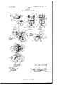
In the accompanying drawings, illustrating the preferred embodiment of my invention, Figure 1 is a side or end view thereof. Figs. 2 and 3 are what may be termed front and rear views of the same, respectively. Fig.
4 is a vertical section taken in a plane pro-' duced through the line of separation between the members or sections of the caster-wheel spindle, with-the wheel or roll and the guard applied thereto shown in side view. Fig. 5 is an inside View of one of the casterwheelspindle sections or members with the wheelguard in position thereon. Fig. 6 is a plan View of the caster. Fig. 7 is an axial section produced through the caster-wheel and its axle or journal bearings.
1n the carrying out of my invention 1 provide a caster-wheel post or spindle 1 of the usual construction in general exterior outline, but formed in two sections or members 1 1, uniting along a line extending through the longitudinal or vertical center of the spindle.
Specification of Letters Patent.
Patented Aug. 29, 1905.
1904. Serial No. 211,834.
Said spindle members or sections have their diagonal portions forming, at their conjunction with the upper cylindric portions I of said members, shoulder members 1 and terminating at their lower ends in preferably disk-like or circular terminals or bearings 1 for the axle or journal 2 of the caster-wheel or roll 3, said journal being separate from the latter. Upon the inside each diagonal portion 1 is recessed, as at 1, preferably angularly, to provide for the reception of a correspond ing plate or guard A, suitably held therein by a dowel at or otherwise and arranged tangentially to the periphery of the caster-wheel or roll 3, and having centrally projecting from its forward and rear edges slightly down ward deflected tapering projections or studs 4:, entering a central circumferential groove A", produced or formed in said roll or Wheel to provide for the effective exclusion of pieces of string, lint, and the like which may adhere to said roll in its rotation from the journal or axle of the latter and its bearings, as also to scrape or remove from the wheel or roll periphery any fine particles or substances adhering thereto. Said angular recessed portions 1 of the spindle members are further recessed or grooved, as at 1, along the upper horizontal lines of said recessed portions to receive the corresponding lateral edges of the angular plate or guard 4 to further aid the holding of the latter in place. The disk-like portions or bearings 1 are recessed or hollowed out internally, as 1, for holding or receiving an absorbent material saturated with a lubricant for automatic application or feeding to the caster-wheel axle or journal. Said recessed or hollowed-out portions 1 are tapered or contracted laterally and terminate in cylindric sockets 1 to conform to and form the bearings proper for the journal or axle of the caster roll or wheel, the openings in the extreme outer ends of said sockets being reduced, so that annular flanges or surfaces are provided at those points to prevent the endwise or outward movement or displacement of said journal or axle and yet the ends of said axle or journal are caused to close the said reductions of the sockets or bearings 1 to exclude dust, &c., at those points.
The caster wheel or roll 3, preferably having a broad periphery or tread, is recessed or reduced from each side inward near said pcriphery, as at 3", to provide for the setting of the disk portions or terminals 1 of the spindle members within the plane of said roll or wheel or its periphery, thus effecting the compact and otherwise desired assembling of the parts, the recesses 1 of said spindle members also providing for the partial reception of said wheel at its peripheral edges to aid in securing the aforesaid result.
A collar 4 encompassingor fitting around the cylindric portion of the spindle and resting upon the shoulder members 1 thereof, primarily holds the spindle members or sections together and has in its upper surface an annular groove or race A, containing antifriction or ball bearings 43, presently again referred to.
A bracket 5, having an upper oblong flat portion 5 and a lower tubular portion 5 and adapted to provide, as later more fully disclosed, for the application or attachment of the caster to the article of furniture, trunk, or other object, has a central opening 5 therethrough for the reception of the upper end of the spindle, it also having preferably above said opening a radially-enlarged circular recess or depression 5 communicating therewith. Through alined apertures 5", produced in the spindle members or sections at a point above the base or bottom of said depression or recess, is inserted a locking pin or key 6, by the projecting of whose ends from said spindle the latter is retained in place and so as to axially pivot it in said bracket or plate, as required in swiveling the caster-wheel in position for a purpose which is apparent. Said pin or key is preferably of the wellknown split spring-metal type, as shown, to provide, as readily understood, for the automatic locking or retention thereof in place in said spindle. To facilitate the insertion and removal of said pin or key, the plate 5* of the bracket5 may be laterally notched or recessed, as at 5, the recesses or notches thus formed having their bottom edges about flush with the bottom of the depression 5 and with which notches are in practice alined or disposed the pin or key receiving openings in the spindle members by accordingly turning the latter by hand when inserting said pin or key in said openings. Said bracket-plate also has upon its under side a circular flange or projection 5, extending below the upper edge of the collar 4 to confine the ball-bearings A" in place in the latter and yet so as not to permit of frictional contact between the parts. It will be noted that the spindle members or sections may also be provided with engaging spurs and recesses upon their meeting surfaces to aid 1n holding the same together.
Latitude is allowed as to details herein, as they may be changed as circumstances suggest without departing from my invention and the latter still'be protected.
1 claim 1. A caster of the character described, em ploying a dirt-guard, consisting of an angular plate held in place inthe spindle members and arranged tangentially to the periphery of the caster-wheel, said wheel having a circumferential groove and said guard having its terminals entering said groove.
2. A caster of the character described, employing half-spindle members, each consisting of a semicylindric upper end portion having a diagonally-extended lower end disk portion provided with an inner concaved surface and a cylindric bearing-socket extending laterally therefrom, means holding said members to gether, a wheel or roll laterally recessed to receive said lower end disk portions and having a tubular hub with its ends seated in said concaved surfaces, and a loose axle for said wheel, extending beyond said hub bearing in said cylindric sockets, at its ends, within the plane of said lower end disk portions.
3. A caster of the character described, employing spindle members having disk-like terminals provided with sockets, a wheel carried by aseparate journal-bearing in said sockets and guard ed thereby against endwise displacement, a collar coupling together said spindle members and having a race containing ballbearings, and a bracket adapted to permit the application of the caster for use, and having a flange encompassing the upper edge of said race.
4. A caster of the character described, em-
ploying spindle members having terminals provided with laterally-tapered recesses to contain a lubricant, said recesses terminating in cylindricsocketawith partially-closed outer ends, and a wheel carried by a journal or axle bearing in said sockets.
5. A caster ofthe character described, employing spindle members having terminals provided with laterally-tapered recesses to contain a lubricant, said recesses being prolonged into cylindric sockets or bearings, and a wheel having annular lateral recesses receiving said terminals and carried by ajournal or axle resting in said sockets or bearings.
In testimony whereof I have signed my name to this specification in the presence of two subscribing witnesses.
ERNEST E. CANEDY.
\Vitnesses:
EDWARD O. KIsLY, N. L. MILLARD.
Priority Applications (1)
| Application Number | Priority Date | Filing Date | Title |
|---|---|---|---|
| US21133404A US798564A (en) | 1904-06-06 | 1904-06-06 | Caster. |
Applications Claiming Priority (1)
| Application Number | Priority Date | Filing Date | Title |
|---|---|---|---|
| US21133404A US798564A (en) | 1904-06-06 | 1904-06-06 | Caster. |
Publications (1)
| Publication Number | Publication Date |
|---|---|
| US798564A true US798564A (en) | 1905-08-29 |
Family
ID=2867052
Family Applications (1)
| Application Number | Title | Priority Date | Filing Date |
|---|---|---|---|
| US21133404A Expired - Lifetime US798564A (en) | 1904-06-06 | 1904-06-06 | Caster. |
Country Status (1)
| Country | Link |
|---|---|
| US (1) | US798564A (en) |
Cited By (1)
| Publication number | Priority date | Publication date | Assignee | Title |
|---|---|---|---|---|
| US2554462A (en) * | 1947-04-25 | 1951-05-22 | Ind Rayon Corp | Strand guard for wheels |
-
1904
- 1904-06-06 US US21133404A patent/US798564A/en not_active Expired - Lifetime
Cited By (1)
| Publication number | Priority date | Publication date | Assignee | Title |
|---|---|---|---|---|
| US2554462A (en) * | 1947-04-25 | 1951-05-22 | Ind Rayon Corp | Strand guard for wheels |
Similar Documents
| Publication | Publication Date | Title |
|---|---|---|
| US798564A (en) | Caster. | |
| US1153838A (en) | Ball-bearing caster and the like. | |
| US331805A (en) | Vehicle-axle | |
| US904921A (en) | Hub, spindle, and axle-arm. | |
| US425786A (en) | Territory | |
| US857200A (en) | Felly for vehicle-wheels. | |
| US425635A (en) | Axle-nut | |
| US1243929A (en) | Bearing for automobile-hubs. | |
| US698557A (en) | Ball-bearing. | |
| US601348A (en) | Antifriction-bearing | |
| US301376A (en) | Oliver k lloyd | |
| US370818A (en) | Hub-attaching device | |
| US512871A (en) | Velocipede | |
| US1147746A (en) | Wheel-hub cap. | |
| US609835A (en) | Ball-bearing | |
| US567946A (en) | Frederick a | |
| US601298A (en) | Ball-bearing | |
| US1053810A (en) | Vehicle-axle. | |
| US107112A (en) | Improvement in carriage-axles | |
| US1239580A (en) | Wheel. | |
| US322584A (en) | Axle-box | |
| US566964A (en) | Wheel-hub | |
| US978015A (en) | Truck. | |
| US280164A (en) | Smith febbis | |
| US798005A (en) | Hub and axle. |