US7978586B2 - Optical pickup device - Google Patents
Optical pickup device Download PDFInfo
- Publication number
- US7978586B2 US7978586B2 US12/090,385 US9038507A US7978586B2 US 7978586 B2 US7978586 B2 US 7978586B2 US 9038507 A US9038507 A US 9038507A US 7978586 B2 US7978586 B2 US 7978586B2
- Authority
- US
- United States
- Prior art keywords
- region
- sub
- light
- pickup device
- block
- Prior art date
- Legal status (The legal status is an assumption and is not a legal conclusion. Google has not performed a legal analysis and makes no representation as to the accuracy of the status listed.)
- Expired - Fee Related, expires
Links
- 230000003287 optical effect Effects 0.000 title claims abstract description 173
- 230000000737 periodic effect Effects 0.000 claims description 53
- 238000000034 method Methods 0.000 claims description 17
- 239000004065 semiconductor Substances 0.000 abstract description 3
- 239000011295 pitch Substances 0.000 description 16
- 238000001514 detection method Methods 0.000 description 9
- 102100030684 Sphingosine-1-phosphate phosphatase 1 Human genes 0.000 description 6
- 101710168942 Sphingosine-1-phosphate phosphatase 1 Proteins 0.000 description 6
- 102100030677 Sphingosine-1-phosphate phosphatase 2 Human genes 0.000 description 6
- 101710168938 Sphingosine-1-phosphate phosphatase 2 Proteins 0.000 description 6
- 230000008901 benefit Effects 0.000 description 4
- 238000010586 diagram Methods 0.000 description 3
- 230000003321 amplification Effects 0.000 description 1
- 238000006073 displacement reaction Methods 0.000 description 1
- 230000000694 effects Effects 0.000 description 1
- 238000003199 nucleic acid amplification method Methods 0.000 description 1
- 230000010363 phase shift Effects 0.000 description 1
- 238000005549 size reduction Methods 0.000 description 1
- 238000009987 spinning Methods 0.000 description 1
Images


Classifications
-
- G—PHYSICS
- G11—INFORMATION STORAGE
- G11B—INFORMATION STORAGE BASED ON RELATIVE MOVEMENT BETWEEN RECORD CARRIER AND TRANSDUCER
- G11B7/00—Recording or reproducing by optical means, e.g. recording using a thermal beam of optical radiation by modifying optical properties or the physical structure, reproducing using an optical beam at lower power by sensing optical properties; Record carriers therefor
- G11B7/12—Heads, e.g. forming of the optical beam spot or modulation of the optical beam
- G11B7/135—Means for guiding the beam from the source to the record carrier or from the record carrier to the detector
- G11B7/1353—Diffractive elements, e.g. holograms or gratings
-
- G—PHYSICS
- G11—INFORMATION STORAGE
- G11B—INFORMATION STORAGE BASED ON RELATIVE MOVEMENT BETWEEN RECORD CARRIER AND TRANSDUCER
- G11B7/00—Recording or reproducing by optical means, e.g. recording using a thermal beam of optical radiation by modifying optical properties or the physical structure, reproducing using an optical beam at lower power by sensing optical properties; Record carriers therefor
- G11B7/08—Disposition or mounting of heads or light sources relatively to record carriers
- G11B7/09—Disposition or mounting of heads or light sources relatively to record carriers with provision for moving the light beam or focus plane for the purpose of maintaining alignment of the light beam relative to the record carrier during transducing operation, e.g. to compensate for surface irregularities of the latter or for track following
- G11B7/0901—Disposition or mounting of heads or light sources relatively to record carriers with provision for moving the light beam or focus plane for the purpose of maintaining alignment of the light beam relative to the record carrier during transducing operation, e.g. to compensate for surface irregularities of the latter or for track following for track following only
- G11B7/0903—Multi-beam tracking systems
-
- G—PHYSICS
- G11—INFORMATION STORAGE
- G11B—INFORMATION STORAGE BASED ON RELATIVE MOVEMENT BETWEEN RECORD CARRIER AND TRANSDUCER
- G11B7/00—Recording or reproducing by optical means, e.g. recording using a thermal beam of optical radiation by modifying optical properties or the physical structure, reproducing using an optical beam at lower power by sensing optical properties; Record carriers therefor
- G11B7/08—Disposition or mounting of heads or light sources relatively to record carriers
- G11B7/09—Disposition or mounting of heads or light sources relatively to record carriers with provision for moving the light beam or focus plane for the purpose of maintaining alignment of the light beam relative to the record carrier during transducing operation, e.g. to compensate for surface irregularities of the latter or for track following
-
- G—PHYSICS
- G11—INFORMATION STORAGE
- G11B—INFORMATION STORAGE BASED ON RELATIVE MOVEMENT BETWEEN RECORD CARRIER AND TRANSDUCER
- G11B7/00—Recording or reproducing by optical means, e.g. recording using a thermal beam of optical radiation by modifying optical properties or the physical structure, reproducing using an optical beam at lower power by sensing optical properties; Record carriers therefor
- G11B7/12—Heads, e.g. forming of the optical beam spot or modulation of the optical beam
- G11B7/125—Optical beam sources therefor, e.g. laser control circuitry specially adapted for optical storage devices; Modulators, e.g. means for controlling the size or intensity of optical spots or optical traces
- G11B7/127—Lasers; Multiple laser arrays
Definitions
- the invention relates to an optical pickup device that is used in an optical information processor for performing processing such as recording of information onto an optical information recording medium and playback or erasure of information recorded on the optical information recording medium.
- Reading recorded information from an optical information recording medium is conducted by converging a light beam emitted from a light source such as a semiconductor laser device on a recording track of the optical disc by using an objective lens and converting reflected light from the optical disc to an electric signal by a photodetector.
- a focus error signal and a tracking error signal are detected and the position of the objective lens is controlled according to surface displacement, eccentricity, and the like of the optical disc.
- a differential push-pull (DPP) method is known as a typical method for detecting a tracking error signal.
- a light beam is separated into three beams: a main beam; a +1 st order diffracted beam; and a ⁇ 1 st order diffracted beam. These three beams are respectively converged on three adjacent guide grooves formed at a prescribed pitch on the optical disc.
- Push-pull signals respectively obtained by detecting reflected light of the +1 st order diffracted beam and the ⁇ 1 st order diffracted beam and performing an arithmetic operation have a phase difference of 180 degrees from a push-pull signal obtained by detecting reflected light of the main beam and performing an arithmetic operation.
- optical discs such as a write once type DVD-R (Recordable) and an erasable type DVD-RW (Disk ReWritable) have a guide groove pitch of 0.74 ⁇ m
- optical discs such as an erasable type DVD-RAM (Random Access Memory) has a guide groove pitch of 1.23 ⁇ m.
- An optical pickup device that enables recording and playback on two or more types of optical discs of different standards has been demanded. The following optical pickup device is proposed in view of this demand (e.g., see Patent document 2).
- a special diffraction grating for separating a light beam is divided into three regions, and the phase of grating grooves periodically provided in each region is sequentially shifted by 90 degrees.
- a tracking error detection method using such a special diffraction grating is called an in-line DPP method, and the in-line DPP method enables stable tracking error detection on a plurality of optical information recording media having different guide groove pitches.
- a conventional optical pickup device using the conventional in-line DPP method has the following problems.
- FIG. 11 shows convergence spots of light beams that are converged on an optical information recording medium by a conventional optical pickup device.
- a convergence spot 101 corresponding to a +1 st order diffracted beam has higher intensity on the right side in a radial direction X of the optical information recording medium and has lower intensity on the left side.
- a convergence spot 102 corresponding to a ⁇ 1 st order diffracted beam has lower intensity on the right side and has higher intensity on the left side.
- the phase of grating grooves 119 a in a region 119 is ahead of that of grating grooves 120 a in a central region 120 by 90 degrees
- the phase of grating grooves 121 a in a region 121 is behind that of the grating grooves 120 a in the central +1 st order diffracted beam that has passed through the region 119 is ahead of that of the +1 st order diffracted beam that has passed through the central region 120 by 90 degrees
- the phase of the +1 st order diffracted beam that has passed through the region 121 is behind that of the +1 st order diffracted beam that has passed through the central region 120 by 90 degrees.
- phase relation of the grating grooves and diffracted beams is opposite for the ⁇ 1 st order diffracted beam.
- the phase of the ⁇ 1 st order diffracted beam that has passed through the region 119 is behind that of the ⁇ 1 st order diffracted beam that has passed through the central region 120 by 90 degrees
- the phase of the ⁇ 1 st order diffracted beam that has passed through the region 121 is ahead of that of the ⁇ 1 st order diffracted beam that has passed through the central region 120 by 90 degrees.
- the +1 st order diffracted beam has larger intensity distribution on the side of the region 121 where the phase is retarded, and the convergence spot 101 corresponding to the +1 st order diffracted beam on the optical information recording medium has higher intensity on the right side and lower intensity on the left side.
- the ⁇ 1 st order diffracted beam has larger intensity distribution on the side of the region 119 where the phase is retarded, and the convergence spot 102 corresponding to the ⁇ 1 st order diffracted beam has lower light intensity on the right side and higher intensity on the left side.
- the convergence spot 101 corresponding to the +1 st order diffracted beam and the convergence spot 102 corresponding to the ⁇ 1 st order diffracted beam have left-right asymmetric intensity distribution
- the phase difference between a push-pull signal obtained by detecting reflected light from the convergence spot 100 corresponding to the main beam and each of push-pull signals respectively obtained by detecting reflected light from the convergence spots 101 and 102 is shifted from 180 degrees. Therefore, each convergence spot cannot be formed on the same guide groove, and stable tracking error signal detection by the in-line DPP method cannot be implemented.
- the invention is made to solve the above problems and it is an object of the invention to implement an optical pickup device for conducting stable tracking error detection on a plurality of optical information recording media having different guide groove pitches while maintaining the advantages of the in-line DPP method.
- an optical pickup device of the invention includes a diffraction grating that is divided into three regions having different phases, and the region located in the middle is divided into a plurality of sub-blocks having different phases.
- a first optical pickup device is an optical pickup device for recording information onto an optical information recording medium and reading and erasing information recorded on the optical information recording medium, and includes: a light source; a diffraction grating for separating a light beam emitted from the light source into at least three light beams; and a photodetector for receiving the separated light beams reflected from the optical information recording medium.
- the diffraction grating is divided into a first region, a second region, and a third region having periodic structures with different phases by a dividing line of a first direction that is a straight line extending in a direction parallel to a tangential direction of a track of the optical information recording medium.
- the second region is located between the first region and the third region and is divided into a first sub-block and a second sub-block having the periodic structures with different phases by a dividing line of a second direction that is a straight line extending in a direction parallel to a radius direction of the optical information recording medium.
- the periodic structure of the first sub-block has a phase difference of approximately 180 degrees from the periodic structure of the second sub-block.
- the periodic structure of the first region has a phase difference of approximately 90 degrees from the periodic structure of the first sub-block.
- the periodic structure of the first region has a phase difference of approximately 180 degrees from the periodic structure of the third region.
- the periodic structure of the first sub-block has a phase difference of approximately 180 degrees from the periodic structure of the second sub-block
- the periodic structure of the first region has a phase difference of approximately 90 degrees from the periodic structure of the first sub-block
- the periodic structure of the first region has a phase difference of approximately 180 degrees from the periodic structure of the third region. Therefore, a phase of a +1 st order diffracted beam that has passed through the first region is ahead of that of the +1 st order diffracted beam that has passed through the first sub-block, and is behind that of the +1 st order diffracted beam that has passed through the second sub-block.
- the phase of the +1 st order diffracted beam that has passed through the third region is ahead of that of the +1 st order diffracted beam that has passed through the second sub-block, and is behind that of the +1 st order diffracted beam that has passed through the first sub-block.
- An opposite phenomenon occurs for a ⁇ 1 st order diffracted beam. Accordingly, unlike the conventional in-line DPP method, the spot shape does not become left-right asymmetric, and intensity distribution becomes left-right symmetric with respect to an extending direction of guide grooves. As a result, an optical pickup device for performing stable tracking error detection on a plurality of optical information recording media having different guide groove pitches can be implemented.
- a center of the light beam emitted from the light source may be positioned on the dividing line of the second direction in the second region of the diffraction grating.
- the light source may include a plurality of light sources, and a center of a light beam emitted from at least one of the plurality of light sources may be positioned on the dividing line of the second direction in the second region of the diffraction grating.
- the light source may include a first light source and a second light source.
- a center of a light beam emitted from the first light source may be positioned in the first region of the diffraction grating or on the dividing line of the first direction that separates the first region and the second region from each other.
- a center of a light beam emitted from the second light source may be positioned in the third region of the diffraction grating or on the dividing line of the first direction that separates the second region and the third region from each other.
- a straight line connecting the center of the light beam emitted from the first light source and the center of the light beam emitted from the second light beam may cross the dividing line of the second direction.
- a length of the first sub-block in the tangential direction is equal to a length of the second sub-block in the tangential direction.
- the at least three light beams may include a 0 th order diffracted beam, a +1 st order diffracted beam, and a order diffracted beam.
- a plurality of guide grooves may be periodically formed on a recording surface of the optical information recording medium, and each of the separated light beams may be converged on one of the plurality of guide grooves.
- the first optical pickup device may further include an arithmetic processing circuit for detecting a tracking error signal by a differential push-pull method based on an output signal of the photodetector.
- the photodetector may include at least three light receiving elements respectively corresponding to the reflected light beams, and each of the light receiving elements may be divided into a plurality of light receiving regions.
- a second optical pickup device is an optical pickup device for recording information onto an optical information recording medium and reading and erasing information recorded on the optical information recording medium, and includes: a light source; a diffraction grating for separating a light beam emitted from the light source into at least three light beams; an objective lens for converging the separated light beams on a recording surface of the optical information recording medium as independent convergence spots; and a photodetector for receiving the light beams converged as the convergence spots and reflected from the optical information recording medium.
- the diffraction grating is divided into a first region, a second region, and a third region having periodic structures with different phases by a dividing line of a first direction that is a straight line extending in a direction parallel to a tangential direction of a track of the optical information recording medium.
- the second region is located between the first region and the third region and is divided into a first sub-block and a second sub-block having the periodic structures with different phases by a dividing line of a second direction that is a straight line extending in a direction parallel to a radius direction of the optical information recording medium.
- the first sub-block and the second sub-block are alternately arranged in the second region in a direction parallel to the tangential direction of the track of the optical information recording medium.
- the periodic structure of the first sub-block has a phase difference of approximately 180 degrees from the periodic structure of the second sub-block.
- the periodic structure of the first region has a phase difference of approximately 90 degrees from the periodic structure of the first sub-block.
- the periodic structure of the first region has a phase difference of approximately 180 degrees from the periodic structure of the third region.
- the first sub-block and the second sub-block are alternately arranged in the second region in the direction parallel to the tangential direction of the track of the optical information recording medium, and the periodic structure of the first sub-block has a phase difference of approximately 180 degrees from the periodic structure of the second sub-block. Therefore, the difference between the total area of the light beam passing through the first sub-blocks and the total area of the light beam passing through the second sub-blocks, that is, the difference between the total light quantity of the light beam passing through the first sub-blocks and the total light quantity of the light beam passing through the second sub-blocks, can be suppressed. As a result, excellent properties can be obtained regardless of the position of the diffraction grating in Y direction, that is, the position of a center of the light beam emitted from the light source.
- a center of the light beam emitted from the light source may be positioned in the second region of the diffraction grating.
- the light source may include a plurality of light sources, and a center of a light beam emitted from at least one of the plurality of light sources may be positioned in the second region of the diffraction grating.
- the light source may include a first light source and a second light source.
- a center of a light beam emitted from the first light source may be positioned in the first region of the diffraction grating or on the dividing line of the first direction that separates the first region and the second region from each other.
- a center of a light beam emitted from the second light source may be positioned in the third region of the diffraction grating or on the dividing line of the first direction that separates the second region and the third region from each other.
- the at least three light beams may include a 0 th order diffracted beam, a +1 st order diffracted beam, and a ⁇ 1 st order diffracted beam.
- a plurality of guide grooves may be periodically formed on a recording surface of the optical information recording medium, and each of the separated light beams may be converged on one of the plurality of guide grooves.
- the second optical pickup device may further include an arithmetic processing circuit for detecting a tracking error signal by a differential push-pull method based on an output signal of the photodetector.
- the photodetector may include at least three light receiving elements respectively corresponding to the reflected light beams, and each of the light receiving elements may be divided into a plurality of light receiving regions.
- the invention can thus implement an optical pickup device for conducting stable tracking error detection on a plurality of optical information recording media having different guide groove pitches while maintaining the advantages of the in-line DPP method.
- FIG. 1 is a block diagram of an optical pickup device according to a first embodiment of the invention
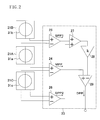
- FIG. 2 is a circuit diagram of a photodetector of the optical pickup device according to the first embodiment of the invention
- FIG. 3 is a plan view of a diffraction grating of the optical pickup device according to the first embodiment of the invention
- FIG. 4 is a plan view showing the shapes of convergence spots formed on a recording surface of an optical information recording medium by the optical pickup device according to the first embodiment of the invention
- FIG. 5 is a waveform diagram of signals obtained by the optical pickup device according to the first embodiment of the invention.
- FIG. 6 is a plan view showing an example of a positional relation between the diffraction grating of the optical pickup device according to the first embodiment of the invention and the respective centers of light beams;
- FIG. 7 is a plan view showing an example of a positional relation between the diffraction grating of the optical pickup device according to the first embodiment of the invention and the respective centers of light beams;
- FIG. 8 is a plan view of a diffraction grating of an optical pickup device according to a second embodiment of the invention.
- FIG. 9 is a plan view showing an example of a positional relation between the diffraction grating of the optical pickup device according to the second embodiment of the invention and the respective centers of light beams;
- FIG. 10 is a plan view showing an example of a positional relation between the diffraction grating of the optical pickup device according to the second embodiment of the invention and the respective centers of light beams;
- FIG. 11 is a plan view showing the shapes of convergence spots formed on a recording surface of an optical information recording medium by a conventional optical pickup device.
- FIG. 12 is a plan view of a diffraction grating of the conventional optical pickup device.
- FIG. 1 schematically shows a structure of an optical pickup device according to the first embodiment.
- the optical pickup device of the first embodiment includes a light source 11 , such as a semiconductor laser element, for emitting a light beam 31 , a diffraction grating 12 for diffracting and separating the emitted light beam 31 into at least three light beams (not shown): a main beam that is a 0 th order diffracted beam; a sub-beam that is a +1 st order diffracted beam; and a sub-beam that is a ⁇ 1 st order diffracted beam, a half mirror 15 for guiding the separated light beams to an optical information recording medium 51 , and an integrated circuit board 17 having a photodetector 16 for receiving the separated light beams reflected from the optical information recording medium 51 . Recording of information to the optical information recording medium 51 and reading of information recorded on the optical information recording medium 51 are conducted with this structure.
- a light source 11 such as a semiconductor laser element
- a collimating lens 18 and an objective lens 19 are placed between the half mirror 15 and the optical information recording medium 51 .
- the light beam 31 emitted from the light source 11 is first diffracted and separated into at least three light beams: a 0 th order diffracted beam; a +1 st order diffracted beam; and a ⁇ 1 st order diffracted beam by the diffraction grating 12 .
- the diffracted beams thus separated are then reflected by the half mirror 15 and reach the objective lens 19 through the collimating lens 18 .
- the 0 th order diffracted beam, the +1 st order diffracted beam, and the ⁇ 1 st order diffracted beam thus obtained by the diffraction grating 1 are then independently converged on a recording surface of the optical information recording medium 51 by the objective lens 19 to form three convergence spots.
- FIG. 2 shows a circuit structure of the integrated circuit board 17 having the photodetector 16 in the optical pickup device of FIG. 1 .
- the integrated circuit board 17 has light receiving elements 21 A, 21 B, and 21 C and an arithmetic processing circuit 23 for performing an arithmetic operation of signals from the light receiving elements.
- a main beam 31 a and two sub-beams 31 b and 31 c separated from the emitted light beam 31 by the diffraction grating 12 are received by the light receiving elements 21 A, 21 B, and 21 C, respectively.
- Each of the light receiving elements 21 A, 21 B, and 21 C is divided into a plurality of light receiving regions.
- the arithmetic processing circuit 23 has subtracters 24 , 25 , and 26 for receiving signals from the light receiving elements 21 A, 21 B, and 21 C, respectively, and an adder 27 , an amplifier 28 , and a subtracter 29 for receiving signals from the subtracters 24 , 25 , and 26 .
- the subtracters 24 , 25 , and 26 receive signals from the light receiving elements 21 A, 21 B, and 21 C and output push-pull signals MPP, SPP 1 , and SPP 2 , respectively.
- the adder 27 , the amplifier 28 , and the subtracter 29 of the arithmetic processing circuit 23 will be described later.
- each light receiving element is divided into two light receiving regions. However, each light receiving element may be divided into three or more light receiving regions.
- each beam in each light receiving element is schematically shown to have a circular shape. However, the beam shape is not limited to this.
- the optical pickup device of this embodiment is characterized in the diffraction grating 12 for diffracting the emitted light beam 31 and is characterized especially in a periodic structure of the diffraction grating 12 .
- FIG. 3 shows a periodic structure, that is, a grating pattern, of the diffraction grating 12 .
- a grating surface of the diffraction grating 12 is divided into three regions: a first region 12 A; a second region 12 B; and a third region 12 C, by two dividing lines D 1 and D 2 extending in an extending direction of guide grooves of the optical information recording medium 51 (hereinafter, referred to as Y direction), that is, in a direction substantially parallel to a tangential direction of a track of the optical information recording medium 51 .
- the first region 12 A and the second region 12 B are adjacent to each other with the dividing line D 1 interposed therebetween
- the second region 12 B and the third region 12 C are adjacent to each other with the dividing line D 2 interposed therebetween.
- the second region 12 B is divided into a first sub-block 13 and a second sub-block 14 by a dividing line D 3 extending in a direction substantially parallel to a radius direction (hereinafter, referred to as X direction) of the optical information recording medium 51 . It is preferable that the first sub-block 13 and the second sub-block 14 have the same length in Y direction.
- the parallel direction means a parallel direction in view of an optical system provided between the diffraction grating and the optical information recording medium.
- grating grooves 12 a are periodically provided along X direction in the first region 12 A, the second region 12 B, and the third region 12 C.
- the phase of the periodic structure of the grating grooves 12 a is different among the first region 12 A, the second region 12 B, and the third region 12 C, and is also different between the first sub-block 13 and the second sub-block 14 .
- the phase of the periodic structure formed by the grating grooves 12 a in the first region 12 A is ahead of that of the periodic structure in the first sub-block 13 of the second region 12 B by substantially 90 degrees (shifted by substantially +90 degrees).
- the arrangement of the grating grooves 12 a in the first region 12 A is shifted by one fourth of a pitch of the grating grooves 12 a in +Y direction from the arrangement of the grating grooves 12 a in the first sub-block 13 .
- the phase of the periodic structure in the third region 12 C is behind that of the periodic structure in the first sub-block 13 by substantially 90 degrees (shifted by substantially ⁇ 90 degrees).
- the arrangement of the grating grooves 12 a in the third region 12 C is shifted by one fourth of the pitch of the grating grooves 12 a in ⁇ Y direction from the arrangement of the grating grooves 12 a in the first sub-block 13 .
- the periodic structure in the first region 12 A has a phase difference of substantially 180 degrees from the periodic structure in the third region 12 C.
- the phase of the periodic structure in the second sub-block 14 is shifted by substantially 180 degrees from that of the periodic structure in the first sub-block 13 .
- the arrangement of the grating grooves 12 a in the second sub-block 14 is shifted by one half of the pitch of the grating grooves 12 a in +Y direction from the arrangement of the grating grooves 12 a in the first sub-block 13 .
- phase of the periodic structure in each region does not have to be shifted exactly by 90 degrees or 180 degrees. Since the convergence spots on the recording surface of the optical information recording medium 51 need only have such a shape as described below, the phase shift may include an error of about ⁇ 10 degrees.
- the center (the center of a light emitting point) L 1 of the light beam 31 emitted from the light source 11 is preferably positioned on the dividing line D 3 within the range of assembly accuracy of the device.
- the emitted light beam 31 incident on the diffraction grating 12 is separated into a main beam and sub-beams having a prescribed phase difference by the respective periodic structures formed in the first region 12 A, the second region 12 B, and the third region 12 C, and the separated sub-beams are then guided to the optical information recording medium 51 .
- optical pickup device of the first embodiment is able to stably detect tracking errors on optical information recording media having different guide groove pitches.
- FIG. 4 shows the shapes of respective convergence spots of the main beam 31 a and the two sub-beams 31 b and 31 c of the emitted light beam generated by the diffraction grating 12 on the recording surface of the optical information recording medium 51 .
- X direction shows the radius direction of the optical information recording medium
- Y direction shows the extending direction of the guide grooves.
- the diffraction grating in the first sub-block 13 has a phase difference of 180 degrees from the diffraction grating in the second sub-block 14 . Therefore, diffracted light that has passed through the first sub-block 13 and diffracted light that has passed through the second sub-block 14 cancel each other, and the respective convergence spots of the sub-beams 31 b and 31 c on the recording surface of the optical information recording medium 51 in FIG. 4 have lower intensity in their centers.
- the phase difference between the first sub-block 13 and the second sub-block 14 may include an error of about ⁇ 10 degrees from 180 degrees.
- the phase of the diffraction grating in the first region 12 A is ahead of that in the first sub-block 13 in the second region 12 B by 90 degrees and is behind that in the second sub-block 14 in the second region 12 B by 90 degrees.
- the phase of the diffraction grating in the third region 12 C is ahead of that in the second sub-block 14 by 90 degrees and is behind that in the first sub-block 13 by 90 degrees.
- the phase of the +1 st order diffracted beam that has passed through the first region 12 A is advanced by 90 degrees from that of the +1 st order diffracted beam that has passed through the first sub-block 13 , and is retarded by 90 degrees from that of the +1 st order diffracted beam that has passed through the second sub-block 14 .
- the phase of the +1 st order diffracted beam that has passed through the third region 12 C is advanced by 90 degrees from that of the +1 st order diffracted beam that has passed through the second sub-block 14 , and is retarded by 90 degrees from that of the +1 st order diffracted beam that has passed through the first sub-block 13 .
- phase difference between the first region 12 A and the second region 12 B and the phase difference between the second region 12 B and the third region 12 C may include an error of about ⁇ 10 degrees from 90 degrees.
- a plurality of guide grooves 51 a are periodically formed on the recording surface of the optical information recording medium 51 .
- the respective convergence spots of the main beam 31 a , the sub-beam 31 b , and the sub-beam 31 c of the emitted light beam converged by the objective lens 19 are located on the same guide groove 51 a , as shown in FIG. 4 .
- the main beam 31 a , the sub beam 31 b , and the sub beam 31 c are reflected at the respective convergence spots, and reflected light beams corresponding to the respective convergence spots are respectively received by the light receiving elements 21 A, 21 B, and 21 C provided in the photodetector 16 .
- the light receiving elements 21 A, 21 B, and 21 C output a push-pull signal MPP corresponding to the main beam 31 a , a push-pull signal SPP 1 corresponding to the sub-beam 31 b , and a push-pull signal SPP 2 corresponding to the sub-beam 31 c , respectively.
- Offset components of the push-pull signals MPP, SPP 1 , and SPP 2 resulting from a radial shift (a shift in the radius direction of the optical information recording medium) of the objective lens 19 and a tilt of the optical information recording medium 51 are generated on the same side (the same phase) for the radial shift of the objective lens 19 or the tilt of the optical information recording medium 51 .
- FIG. 5 shows respective output waveforms of the push-pull signals MPP, SPP 1 , and SPP 2 and the DPP signal obtained by the above formula (1).
- the ordinate indicates signal strength and the abscissa indicates a relative position of the convergence spot on the optical information recording medium 51 .
- SPP 1 and SPP 2 have a phase difference of exactly 180 degrees from MPP. Since the DPP signal obtained by the above formula (1) has a proper value, each convergence spot can be formed on the same guide groove.
- the inputs of the adder 27 are respectively connected to the respective outputs of the subtracters 25 and 26 , and the input of the amplifier 28 is connected to the output of the adder 27 .
- the inputs of the subtracter 29 are respectively connected to the output of the subtracter 24 and the output of the amplifier 28 .
- the arithmetic operation shown by the above formula (1) can be performed with this structure.
- the coefficient k in the formula (1) is used to correct the difference in light intensity among the main beam 31 a , the sub-beam 31 b , and the sub-beam 31 c that are reflected from the optical information recording medium 51 .
- the coefficient k is a/2b.
- the coefficient k is a constant that is determined according to the optical information recording medium 51 .
- a conventional structure may be used as a signal processing circuit.
- the structure shown in this embodiment has one light source. However, there may be a plurality of light sources. In this case, it is preferable that the center of a light beam emitted from at least one of the plurality of light sources is positioned on the dividing line D 3 in the second region 12 B as shown in FIG. 6 .
- the center of a light beam L 1 emitted from a first light source of the plurality of light sources and the center of a light beam L 2 emitted from a second light source may be positioned so that a straight line connecting the center of the light beam L 1 and the center of the light beam L 2 crosses the dividing line D 3 in the second region 12 B.
- the position of the center L 3 of a light beam emitted from a third light source is not particularly limited.
- the third light source need not necessarily be provided.
- FIG. 8 shows a diffraction grating 12 used in an optical pickup device of the second embodiment.
- the same elements as those in FIG. 3 are denoted by the same reference numerals and characters and description thereof will be omitted.
- the first sub-block 13 and the second sub-block 14 are alternately arranged in the second region 12 B.
- the difference between the total area of the emitted light beam 31 passing through the first sub-blocks 13 and the total area of the emitted light beam 31 passing through the second sub-blocks 14 that is, the difference between the total light quantity of the emitted light beam 31 passing through the first sub-blocks 13 and the total light quantity of the emitted light beam 31 passing through the second sub-blocks 14 , can be suppressed. Accordingly, excellent properties can be obtained regardless of the position of the diffraction grating 12 in Y direction, that is, the position of the center of the light beam emitted from the light source 11 .
- the first sub-block 13 and the second sub-block 14 are repeated three times.
- the number of repetitions is not limited.
- the order of repetition may be reversed.
- the first sub-block 13 and the second sub-block 14 have the same length in Y direction. However, the first sub-block 13 and the second sub-block 14 may have different lengths in Y direction. It is preferable that the sum of the lengths of the first sub-blocks 13 in Y direction is equal to the sum of the lengths of the second sub-blocks 14 in Y direction.
- FIG. 8 shows an example in which the center L 1 of the light beam 31 emitted from the light source 11 is positioned on a dividing line that separates the first sub-block 13 and the second sub-block 14 from each other.
- the invention is not limited to this, and the center of the light beam 31 emitted from the light source 11 need only be positioned in the second region 12 B.
- the center L 1 of a light beam emitted from a first light source of the plurality of light sources may be positioned in the first region 12 A and the center L 2 of a light beam emitted from a second light source may be positioned in the third region 12 C.
- the position of the center L 3 of a light beam emitted from a third light source is not particularly limited.
- the third light source need not necessarily be provided.
- the type of the optical information recording medium 51 is not particularly limited, and DVDs including a DVD-ROM, a DVD-RAM, a DVD-R, and a DVD-RW and CDs including a CD-ROM, a CD-R, and a CD-RW may be used as the optical information recording medium 51 .
- the wavelength of the emitted light beam 31 is determined according to the optical information recording medium 51 , and is in the range of about 650 nm to about 780 nm in the case of a DVD and a CD.
- stable tracking error signal detection can be performed on a DVD having a guide groove pitch of 0.74 ⁇ m such as a DVD-R and a DVD having a guide groove pitch of 1.23 ⁇ m such as a DVD-RAM.
- the diffraction grating 12 is placed between the light source 11 and the half mirror 15 in the optical system shown in FIG. 1 .
- the diffraction grating 12 may alternatively be placed, for example, between the half mirror 15 and the collimating lens 18 .
- an optical system in which a light source and a photodetector are integrated for example, an optical system that does not use a half mirror
- the diffraction grating may be placed between the light source and the collimating lens.
- the grating grooves in each region of the diffraction grating 12 are formed along X direction, that is, the radius direction of the optical information recording medium.
- the grating grooves may alternatively be formed in a direction oblique to X direction.
- the optical pickup device of each embodiment can be used for various optical information recording media having different guide groove pitches and achieves tracking error signal detection that enables more stable recording and playback.
- the optical pickup device of each embodiment can implement size reduction, simplification, cost reduction, higher efficiency, and the like in DVD- and CD-type recording devices and playback devices.
- the optical pickup device of each embodiment is very useful as an optical pickup device having a function to detect signals such as a playback signal, a recording signal, and various servo signals which are used in an optical head device serving as a main part of an optical information processor for performing processing, such as recording, playback, and erasure of information, on an optical information recording medium such as an optical disc.
- the invention can implement an optical pickup device for performing stable tracking error detection on a plurality of optical information recording media having different guide groove pitches while maintaining the advantages of the in-line DPP method.
- the optical pickup device of the invention is useful as devices such as an optical pickup device that is used in an optical information processor for performing processing such as recording of information onto an optical information recording medium and playback or erasure of information recorded on an optical information recording medium.
Landscapes
- Physics & Mathematics (AREA)
- Optics & Photonics (AREA)
- Optical Recording Or Reproduction (AREA)
- Optical Head (AREA)
Abstract
Description
- Patent document 1: Japanese Patent Publication for Opposition No. 4-34212
- Patent document 2: Japanese Laid-Open Patent Publication No. 2004-145915
| DESCRIPTION OF THE |
| 11 | |
||
| 12 | |
||
| 12A | |
||
| 12B | |
||
| 12C | |
||
| | grating groove | ||
| 13 | first sub-block | ||
| 14 | second sub-block | ||
| 15 | |
||
| 16 | |
||
| 17 | integrated |
||
| 18 | collimating |
||
| 19 | |
||
| 21A | |
||
| 21B | light receiving element | ||
| 21C | |
||
| 23 | |
||
| 24 | |
||
| 25 | |
||
| 26 | |
||
| 27 | |
||
| 28 | |
||
| 29 | |
||
| 31 | emitted |
||
| 31a | | ||
| 31b | |
||
| 31c | sub-beam | ||
| 51 | optical information recording medium | ||
| 51a | guide groove | ||
DPP=MPP−k×(SPP1+SPP2) (1)
where k is an amplification factor of the
Claims (17)
Applications Claiming Priority (3)
| Application Number | Priority Date | Filing Date | Title |
|---|---|---|---|
| JP2006-339532 | 2006-12-18 | ||
| JP2006339532A JP4444947B2 (en) | 2006-12-18 | 2006-12-18 | Optical pickup device |
| PCT/JP2007/064143 WO2008075478A1 (en) | 2006-12-18 | 2007-07-18 | Optical pickup device |
Publications (2)
| Publication Number | Publication Date |
|---|---|
| US20100177618A1 US20100177618A1 (en) | 2010-07-15 |
| US7978586B2 true US7978586B2 (en) | 2011-07-12 |
Family
ID=39536114
Family Applications (1)
| Application Number | Title | Priority Date | Filing Date |
|---|---|---|---|
| US12/090,385 Expired - Fee Related US7978586B2 (en) | 2006-12-18 | 2007-07-18 | Optical pickup device |
Country Status (6)
| Country | Link |
|---|---|
| US (1) | US7978586B2 (en) |
| JP (1) | JP4444947B2 (en) |
| KR (1) | KR20090092692A (en) |
| CN (1) | CN101356579A (en) |
| TW (1) | TW200828290A (en) |
| WO (1) | WO2008075478A1 (en) |
Families Citing this family (1)
| Publication number | Priority date | Publication date | Assignee | Title |
|---|---|---|---|---|
| JP4444977B2 (en) | 2007-02-01 | 2010-03-31 | パナソニック株式会社 | Optical pickup device |
Citations (10)
| Publication number | Priority date | Publication date | Assignee | Title |
|---|---|---|---|---|
| JPS6194246A (en) | 1984-10-15 | 1986-05-13 | Sony Corp | Tracking error detection system |
| JPH0434212A (en) | 1990-05-31 | 1992-02-05 | Ntn Corp | Double row tapered roller bearing with vertex of contact angles inside of bearing |
| US20040081064A1 (en) | 2002-10-22 | 2004-04-29 | Hitachi, Ltd. | Optical pickup and optical information recording apparatus using the same |
| US20050276206A1 (en) | 2004-06-11 | 2005-12-15 | Nec Corporation | Optical head device and optical information recording or reproducing device |
| JP2006228304A (en) | 2005-02-16 | 2006-08-31 | Sanyo Electric Co Ltd | Tracking controller |
| JP2007035193A (en) | 2005-07-28 | 2007-02-08 | Sharp Corp | Optical pickup device |
| JP2007042252A (en) | 2005-06-29 | 2007-02-15 | Enplas Corp | Optical element, optical pickup device, and optical information recording and / or reproducing device |
| JP2007122779A (en) | 2005-10-25 | 2007-05-17 | Sony Corp | Optical pickup and optical disc apparatus |
| JP2007141425A (en) | 2005-10-17 | 2007-06-07 | Sanyo Electric Co Ltd | Optical pickup device and optical disk device |
| US20080253263A1 (en) * | 2006-08-25 | 2008-10-16 | Yoshiaki Komma | Optical head device and diffractive element, optical information apparatus, computer, disc player, car navigation system, optical disc recorder, and vehicle |
-
2006
- 2006-12-18 JP JP2006339532A patent/JP4444947B2/en not_active Expired - Fee Related
-
2007
- 2007-07-18 WO PCT/JP2007/064143 patent/WO2008075478A1/en not_active Ceased
- 2007-07-18 CN CNA2007800011220A patent/CN101356579A/en active Pending
- 2007-07-18 US US12/090,385 patent/US7978586B2/en not_active Expired - Fee Related
- 2007-07-18 KR KR1020087024117A patent/KR20090092692A/en not_active Withdrawn
- 2007-12-03 TW TW096145949A patent/TW200828290A/en unknown
Patent Citations (12)
| Publication number | Priority date | Publication date | Assignee | Title |
|---|---|---|---|---|
| JPS6194246A (en) | 1984-10-15 | 1986-05-13 | Sony Corp | Tracking error detection system |
| JPH0434212A (en) | 1990-05-31 | 1992-02-05 | Ntn Corp | Double row tapered roller bearing with vertex of contact angles inside of bearing |
| US20040081064A1 (en) | 2002-10-22 | 2004-04-29 | Hitachi, Ltd. | Optical pickup and optical information recording apparatus using the same |
| JP2004145915A (en) | 2002-10-22 | 2004-05-20 | Hitachi Ltd | Optical pickup and optical information recording device or reproducing device using the same |
| US20050276206A1 (en) | 2004-06-11 | 2005-12-15 | Nec Corporation | Optical head device and optical information recording or reproducing device |
| JP2005353187A (en) | 2004-06-11 | 2005-12-22 | Nec Corp | Optical head device and optical information recording and reproducing device |
| JP2006228304A (en) | 2005-02-16 | 2006-08-31 | Sanyo Electric Co Ltd | Tracking controller |
| JP2007042252A (en) | 2005-06-29 | 2007-02-15 | Enplas Corp | Optical element, optical pickup device, and optical information recording and / or reproducing device |
| JP2007035193A (en) | 2005-07-28 | 2007-02-08 | Sharp Corp | Optical pickup device |
| JP2007141425A (en) | 2005-10-17 | 2007-06-07 | Sanyo Electric Co Ltd | Optical pickup device and optical disk device |
| JP2007122779A (en) | 2005-10-25 | 2007-05-17 | Sony Corp | Optical pickup and optical disc apparatus |
| US20080253263A1 (en) * | 2006-08-25 | 2008-10-16 | Yoshiaki Komma | Optical head device and diffractive element, optical information apparatus, computer, disc player, car navigation system, optical disc recorder, and vehicle |
Also Published As
| Publication number | Publication date |
|---|---|
| US20100177618A1 (en) | 2010-07-15 |
| TW200828290A (en) | 2008-07-01 |
| CN101356579A (en) | 2009-01-28 |
| KR20090092692A (en) | 2009-09-01 |
| JP2008152853A (en) | 2008-07-03 |
| JP4444947B2 (en) | 2010-03-31 |
| WO2008075478A1 (en) | 2008-06-26 |
Similar Documents
| Publication | Publication Date | Title |
|---|---|---|
| JP4151313B2 (en) | Optical regenerator | |
| US7898927B2 (en) | Optical pickup device | |
| US7940631B2 (en) | Optical pickup device | |
| US7535814B2 (en) | Optical pickup device | |
| US7706220B2 (en) | Photodetector, diffraction grating, optical pickup and optical disc apparatus | |
| US7978586B2 (en) | Optical pickup device | |
| KR100717020B1 (en) | Optical pickup device that detects and compensates for spherical aberration according to the change in thickness of the recording layer | |
| JP4654085B2 (en) | Photodetector, optical pickup and optical disc apparatus | |
| JP2008176905A (en) | Optical pickup device | |
| US20060215508A1 (en) | Optical semiconductor device | |
| US20090168626A1 (en) | Optical pickup device and photodetector | |
| JP2007287278A (en) | Optical pickup device | |
| US20110090776A1 (en) | Optical head device, optical information processing apparatus, and signal detecting method | |
| JP2007226866A (en) | Optical detector, diffraction grating, optical pickup, optical disk device | |
| JP2005078747A (en) | Optical information recording / reproducing apparatus and optical pickup mounted thereon | |
| JP2005293716A (en) | Optical pickup | |
| JP2008287807A (en) | Optical pickup and optical disc apparatus |
Legal Events
| Date | Code | Title | Description |
|---|---|---|---|
| AS | Assignment |
Owner name: MATSUSHITA ELECTRIC INDUSTRIAL CO., LTD., JAPAN Free format text: ASSIGNMENT OF ASSIGNORS INTEREST;ASSIGNORS:SHIMADA, NAOTO;YAMAMOTO, HIROAKI;NAKANISHI, NAOKI;AND OTHERS;SIGNING DATES FROM 20080222 TO 20080303;REEL/FRAME:021160/0610 |
|
| AS | Assignment |
Owner name: PANASONIC CORPORATION, JAPAN Free format text: CHANGE OF NAME;ASSIGNOR:MATSUSHITA ELECTRIC INDUSTRIAL CO., LTD.;REEL/FRAME:021832/0215 Effective date: 20081001 |
|
| STCF | Information on status: patent grant |
Free format text: PATENTED CASE |
|
| FEPP | Fee payment procedure |
Free format text: PAYOR NUMBER ASSIGNED (ORIGINAL EVENT CODE: ASPN); ENTITY STATUS OF PATENT OWNER: LARGE ENTITY |
|
| FPAY | Fee payment |
Year of fee payment: 4 |
|
| AS | Assignment |
Owner name: PANNOVA SEMIC, LLC, CALIFORNIA Free format text: ASSIGNMENT OF ASSIGNORS INTEREST;ASSIGNOR:PANASONIC CORPORATION;REEL/FRAME:036065/0273 Effective date: 20141226 |
|
| FEPP | Fee payment procedure |
Free format text: PAYER NUMBER DE-ASSIGNED (ORIGINAL EVENT CODE: RMPN); ENTITY STATUS OF PATENT OWNER: LARGE ENTITY Free format text: PAYOR NUMBER ASSIGNED (ORIGINAL EVENT CODE: ASPN); ENTITY STATUS OF PATENT OWNER: LARGE ENTITY |
|
| MAFP | Maintenance fee payment |
Free format text: PAYMENT OF MAINTENANCE FEE, 8TH YEAR, LARGE ENTITY (ORIGINAL EVENT CODE: M1552); ENTITY STATUS OF PATENT OWNER: LARGE ENTITY Year of fee payment: 8 |
|
| FEPP | Fee payment procedure |
Free format text: MAINTENANCE FEE REMINDER MAILED (ORIGINAL EVENT CODE: REM.); ENTITY STATUS OF PATENT OWNER: LARGE ENTITY |
|
| LAPS | Lapse for failure to pay maintenance fees |
Free format text: PATENT EXPIRED FOR FAILURE TO PAY MAINTENANCE FEES (ORIGINAL EVENT CODE: EXP.); ENTITY STATUS OF PATENT OWNER: LARGE ENTITY |
|
| STCH | Information on status: patent discontinuation |
Free format text: PATENT EXPIRED DUE TO NONPAYMENT OF MAINTENANCE FEES UNDER 37 CFR 1.362 |
|
| FP | Lapsed due to failure to pay maintenance fee |
Effective date: 20230712 |