US7972720B2 - Method of electric coupling of a connection to a current output - Google Patents
Method of electric coupling of a connection to a current output Download PDFInfo
- Publication number
- US7972720B2 US7972720B2 US10/943,013 US94301304A US7972720B2 US 7972720 B2 US7972720 B2 US 7972720B2 US 94301304 A US94301304 A US 94301304A US 7972720 B2 US7972720 B2 US 7972720B2
- Authority
- US
- United States
- Prior art keywords
- connection
- current output
- casing
- electrode
- cover
- Prior art date
- Legal status (The legal status is an assumption and is not a legal conclusion. Google has not performed a legal analysis and makes no representation as to the accuracy of the status listed.)
- Expired - Fee Related, expires
Links
Images


Classifications
-
- H—ELECTRICITY
- H01—ELECTRIC ELEMENTS
- H01M—PROCESSES OR MEANS, e.g. BATTERIES, FOR THE DIRECT CONVERSION OF CHEMICAL ENERGY INTO ELECTRICAL ENERGY
- H01M10/00—Secondary cells; Manufacture thereof
- H01M10/04—Construction or manufacture in general
- H01M10/0431—Cells with wound or folded electrodes
-
- H—ELECTRICITY
- H01—ELECTRIC ELEMENTS
- H01M—PROCESSES OR MEANS, e.g. BATTERIES, FOR THE DIRECT CONVERSION OF CHEMICAL ENERGY INTO ELECTRICAL ENERGY
- H01M50/00—Constructional details or processes of manufacture of the non-active parts of electrochemical cells other than fuel cells, e.g. hybrid cells
- H01M50/50—Current conducting connections for cells or batteries
- H01M50/528—Fixed electrical connections, i.e. not intended for disconnection
-
- H—ELECTRICITY
- H01—ELECTRIC ELEMENTS
- H01M—PROCESSES OR MEANS, e.g. BATTERIES, FOR THE DIRECT CONVERSION OF CHEMICAL ENERGY INTO ELECTRICAL ENERGY
- H01M50/00—Constructional details or processes of manufacture of the non-active parts of electrochemical cells other than fuel cells, e.g. hybrid cells
- H01M50/50—Current conducting connections for cells or batteries
- H01M50/531—Electrode connections inside a battery casing
- H01M50/533—Electrode connections inside a battery casing characterised by the shape of the leads or tabs
-
- H—ELECTRICITY
- H01—ELECTRIC ELEMENTS
- H01M—PROCESSES OR MEANS, e.g. BATTERIES, FOR THE DIRECT CONVERSION OF CHEMICAL ENERGY INTO ELECTRICAL ENERGY
- H01M50/00—Constructional details or processes of manufacture of the non-active parts of electrochemical cells other than fuel cells, e.g. hybrid cells
- H01M50/50—Current conducting connections for cells or batteries
- H01M50/531—Electrode connections inside a battery casing
- H01M50/534—Electrode connections inside a battery casing characterised by the material of the leads or tabs
-
- H—ELECTRICITY
- H01—ELECTRIC ELEMENTS
- H01M—PROCESSES OR MEANS, e.g. BATTERIES, FOR THE DIRECT CONVERSION OF CHEMICAL ENERGY INTO ELECTRICAL ENERGY
- H01M50/00—Constructional details or processes of manufacture of the non-active parts of electrochemical cells other than fuel cells, e.g. hybrid cells
- H01M50/50—Current conducting connections for cells or batteries
- H01M50/531—Electrode connections inside a battery casing
- H01M50/536—Electrode connections inside a battery casing characterised by the method of fixing the leads to the electrodes, e.g. by welding
-
- H—ELECTRICITY
- H01—ELECTRIC ELEMENTS
- H01M—PROCESSES OR MEANS, e.g. BATTERIES, FOR THE DIRECT CONVERSION OF CHEMICAL ENERGY INTO ELECTRICAL ENERGY
- H01M50/00—Constructional details or processes of manufacture of the non-active parts of electrochemical cells other than fuel cells, e.g. hybrid cells
- H01M50/50—Current conducting connections for cells or batteries
- H01M50/531—Electrode connections inside a battery casing
- H01M50/538—Connection of several leads or tabs of wound or folded electrode stacks
-
- Y—GENERAL TAGGING OF NEW TECHNOLOGICAL DEVELOPMENTS; GENERAL TAGGING OF CROSS-SECTIONAL TECHNOLOGIES SPANNING OVER SEVERAL SECTIONS OF THE IPC; TECHNICAL SUBJECTS COVERED BY FORMER USPC CROSS-REFERENCE ART COLLECTIONS [XRACs] AND DIGESTS
- Y02—TECHNOLOGIES OR APPLICATIONS FOR MITIGATION OR ADAPTATION AGAINST CLIMATE CHANGE
- Y02E—REDUCTION OF GREENHOUSE GAS [GHG] EMISSIONS, RELATED TO ENERGY GENERATION, TRANSMISSION OR DISTRIBUTION
- Y02E60/00—Enabling technologies; Technologies with a potential or indirect contribution to GHG emissions mitigation
- Y02E60/10—Energy storage using batteries
-
- Y—GENERAL TAGGING OF NEW TECHNOLOGICAL DEVELOPMENTS; GENERAL TAGGING OF CROSS-SECTIONAL TECHNOLOGIES SPANNING OVER SEVERAL SECTIONS OF THE IPC; TECHNICAL SUBJECTS COVERED BY FORMER USPC CROSS-REFERENCE ART COLLECTIONS [XRACs] AND DIGESTS
- Y02—TECHNOLOGIES OR APPLICATIONS FOR MITIGATION OR ADAPTATION AGAINST CLIMATE CHANGE
- Y02P—CLIMATE CHANGE MITIGATION TECHNOLOGIES IN THE PRODUCTION OR PROCESSING OF GOODS
- Y02P70/00—Climate change mitigation technologies in the production process for final industrial or consumer products
- Y02P70/50—Manufacturing or production processes characterised by the final manufactured product
-
- Y—GENERAL TAGGING OF NEW TECHNOLOGICAL DEVELOPMENTS; GENERAL TAGGING OF CROSS-SECTIONAL TECHNOLOGIES SPANNING OVER SEVERAL SECTIONS OF THE IPC; TECHNICAL SUBJECTS COVERED BY FORMER USPC CROSS-REFERENCE ART COLLECTIONS [XRACs] AND DIGESTS
- Y10—TECHNICAL SUBJECTS COVERED BY FORMER USPC
- Y10T—TECHNICAL SUBJECTS COVERED BY FORMER US CLASSIFICATION
- Y10T29/00—Metal working
- Y10T29/49—Method of mechanical manufacture
- Y10T29/49002—Electrical device making
- Y10T29/49108—Electric battery cell making
- Y10T29/49114—Electric battery cell making including adhesively bonding
Definitions
- the invention relates to the electric coupling of an electrode connection to a current output terminal.
- the invention applies in particular to electrochemical generators intended for portable equipment, the capacity of which is generally less than 20 Ah, particularly for sealed cylindrical secondary electrochemical generators with spirally wound electrodes.
- the invention relates in particular to the method for producing this coupling.
- An electrochemical generator comprises an electrochemical stack comprising an alternating sequence of positive and negative electrodes framing a separator impregnated with electrolyte.
- Each electrode most often comprises a metal current conductor support carrying the electrochemically active material on at least one of its surfaces.
- the electrode is connected electrically to a current output which ensures electrical continuity between the electrode and the external application with which the generator is associated.
- This current output can be the container of the generator, such as for example the cover, or a current output terminal mounted on the container.
- Standard cylindrical generators generally have spiralling of an electrochemical stack forming a cylindrical body.
- the spiralling then comprises two electrodes with respectively positive and negative polarity framing a separator.
- One of these ways is the use of at least one thin conducting strip or thin metal band, one end of which is welded to the end face of the current conductor support of one of the electrodes and the other end is welded to the part of the current output situated inside the container, for example to the internal surface of the cover or to the internal part of a terminal.
- Another method consists in bringing a flat current collector into contact with one of the flat ends of the cylindrical body formed by the winding of a portion of the current conductor support of one of the electrodes.
- the two electrodes have a slight difference in height so that each end of the cylindrical body is formed by the spirally wound portion of the current conductor support of only one of the two electrodes.
- the flat current collector in the shape of a disk for example, can itself be provided with at least one thin conducting strip connected to the current output.
- EP-0 818 842 discloses a cylindrical alkaline electrolyte generator comprising two spirally wound electrodes so that each end of the cylindrical body is formed by the winding of a portion of the conductor support of a single electrode.
- a perforated flat current collector is welded to the upper end face of the conductor support of one of the electrodes.
- a collecting plate connected to the flat connector is spot-welded to the internal surface of the cover while the cover is in a position perpendicular to its closed position. The cover is then folded down in order to hermetically seal the casing by means of an insulation gasket.
- the collecting plate has sufficient length so as to have, once folded, a fairly extensive contact surface with the internal surface of the cover.
- a voltage of 24 Volts is applied in a discharge direction between the cover and the bottom of the casing so as to cause the flow of a current of 1 KA for 15 msec.
- a second welding is carried out between the collecting plate and the internal surface of the cover.
- the electric coupling thus obtained has better mechanical strength in a vibration test.
- the positioning of the collecting plate on the internal surface of the cover when closing the generator proves to be a delicate operation to carry out.
- a disconnection of the first weld can occur or melting of the collecting plate if the duration and intensity of the current are not perfectly controlled.
- the invention sets out to provide a method of electric coupling between a connection electrically connected to an electrode and a current output in order to produce a secondary electrochemical generator the internal impedance of which is reduced compared with the generators obtained by the known methods.
- the invention provides a method for producing a secondary electrochemical generator comprising a container comprising a casing and a cover carrying a current output which is electrically insulated from the casing, and at least one electrode which is electrically connected to a connection, characterized in that it comprises a stage of electric coupling the connection to the current output comprising the following steps:
- the current output is intended to bring into an electrical relationship the cylindrical body situated inside the generator, and more specifically the electrodes, with an external application to be supplied. It can be constituted by the cover itself which is then set on the casing of the container by means of an insulation gasket, or by means of a terminal comprising a central conductive part projecting into and out of the generator and a peripheral insulation part ensuring the joint with the cover.
- connection of the invention is the use of a connection the length of which is much smaller than that of the connections used in the generators of the prior art.
- connection of the invention has a smaller length than that which it would need to be in contact with the current output when the cover is not in its closed position.
- the method according to the present invention allows this welding to be carried out after the generator has been closed. Once this welding has been carried out, its quality is checked with a voltage measurement which provides information on the value of the contact resistance.
- the electrode comprises a conductor support, at least one surface of which is covered with a layer containing the electrochemically active material.
- the electrode is spirally wound so as to form a cylindrical body, the flat end of which is constituted by the end face of the support.
- the connection comprises a flat part which is welded on the end face of the electrode conductor support in order to produce the electrical connection between the connection and the electrode.
- connection comprises a flat part intended to be connected to the electrode and at least one tongue which is intended to be connected to the current output.
- the flat part and the tongue are in different planes so that the tongue is in contact with the current output.
- the tongue is such that it forms a spring resting on the internal part of the current output. For low power generators, the contact which is thus ensured may appear to be sufficient to ensure electrical continuity. But for higher power generators the connection needs to be welded to the current output.
- the voltage applied between the casing and the current output is comprised between 1.3 V and 15 V.
- the current applied between the casing and the current output comprises a current spike comprised between 500 and 15000 A.
- connections are in line connected to each other by meltable points. According to a particular embodiment of the invention, the connections are separated from each other by melting their connection points.
- the invention also provides an electrochemical generator produced by the method described previously, comprising a container comprising a casing and a cover carrying a current output which is electrically insulated from the casing and at least one electrode which is electrically connected to a connection.
- the length of the connection is not sufficient for the connection to be in contact with the current output when the cover is not in its closed position.
- connection is preferably made of stainless steel, steel, nickel-coated steel or nickel.
- connection comprises a flat part intended to be connected to at least one electrode and at least one tongue intended to be connected to the current output.
- the electrochemical generator is cylindrical.
- the electrode comprises a conductor support, at least one surface of which is covered with a layer containing the electrochemically active material.
- the electrode is spirally wound so as to form a cylindrical body, the flat end of which is constituted by an end face of the support.
- the flat part of the connection is welded to the flat end of the cylindrical body.
- FIG. 1 is a diagrammatic cross-sectional view representing the welding of a connection to a current output according to the method of the prior art
- FIG. 2 is a diagrammatic cross-sectional view representing the welding of a connection to a current output according to the method of the invention
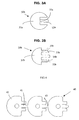
- FIGS. 3A and 3B show two examples of a connection which can be used in the method according to the invention.
- FIG. 4 shows a strip before cutting composed of several connections which can be used in the method according to the invention.
- FIG. 1 shows in cross-section an electrochemical generator 1 comprising electrodes 2 combined in a container made up of a casing 3 and a cover 4 .
- the casing 3 and the cover 4 are joined by means of an insulation gasket 5 .
- the generator 1 contains a connection 11 which is made up of a flat part 12 welded to the end face of the electrodes 2 of the same polarity, and a plate 13 .
- the plate 13 is welded to the cover 4 which constitutes a current output here.
- the plate 13 is applied to the internal surface of the cover 4 .
- the plate 13 /cover 4 assembly is pinched between an electrode 14 and a counter-electrode 15 in order to carry out the welding.
- the cover 4 forms an angle 16 with the plane 17 of its closed position so as to clear a passage which is sufficient for the electrode 14 and the counter-electrode 15 .
- the cover 4 is folded down on the casing 3 .
- FIG. 2 the main elements of the generator 1 of FIG. 1 are seen.
- the generator 20 contains a connection 21 which is composed of a flat part 22 welded to the end face of the electrodes 2 and a short tongue 23 which forms an angle 24 with the plane 25 of the flat part.
- the cover 4 is folded back on the casing 3 and joins to it by means of the insulation gasket 5 .
- the value of the angle 24 is such that once the cover 4 is in place, the tongue 23 is applied to the internal surface of the cover 4 which constitutes a current output here.
- the tongue 23 is welded to the cover 4 using a first electrode 26 applied to the bottom of the casing 3 and with a second electrode 27 positioned on the external surface of the cover 4 to the right of the support area of the tongue 23 on the internal surface of the cover 4 .
- a voltage higher than the voltage of the generator 20 is applied between the two electrodes 26 , 27 for a duration of 5 msec to 30 msec with a current surge comprised between 5000 A and 15000 A.
- FIGS. 3A and 3B show two variants of the shape for a connection which can be used in the method according to the invention.
- the connection 30 a comprises a flat part 31 a and a tongue 32 a , 32 b which is lifted up along the fold line 33 a into a plane forming an angle with that of the flat part 31 a.
- connection 30 b comprises a flat part 31 b and two tongues 32 b and 33 b which are lifted up respectively along the fold lines 34 b and 35 b into a plane forming an angle with that of the flat part 31 b .
- welding is carried out by the method according to the invention respectively on each tongue 32 b and 33 b.
- FIG. 4 a strip of short connections 40 according to the invention is shown comprising a tongue 41 extending from a flat part 42 .
- the connections 40 are connected to each other with a tongue 41 .
Landscapes
- Chemical & Material Sciences (AREA)
- Chemical Kinetics & Catalysis (AREA)
- Electrochemistry (AREA)
- General Chemical & Material Sciences (AREA)
- Engineering & Computer Science (AREA)
- Manufacturing & Machinery (AREA)
- Connection Of Batteries Or Terminals (AREA)
- Secondary Cells (AREA)
Abstract
Description
-
- a first end of the connection is electrically connected to the electrode,
- the cover is placed on the casing in order to close the container so that a second end of the connection is in physical contact with the current output, the length of the connection not allowing it to come into contact with the current output when the cover is not in the closed position of the generator,
- an electric current is applied between the casing and the current output so as to weld the second end of the connection to the current output.
Claims (11)
Applications Claiming Priority (2)
| Application Number | Priority Date | Filing Date | Title |
|---|---|---|---|
| FR0311010 | 2003-09-19 | ||
| FR0311010A FR2860103B1 (en) | 2003-09-19 | 2003-09-19 | METHOD FOR ELECTRICALLY CONNECTING A CONNECTION TO A CURRENT OUTPUT |
Publications (2)
| Publication Number | Publication Date |
|---|---|
| US20050064287A1 US20050064287A1 (en) | 2005-03-24 |
| US7972720B2 true US7972720B2 (en) | 2011-07-05 |
Family
ID=34224351
Family Applications (1)
| Application Number | Title | Priority Date | Filing Date |
|---|---|---|---|
| US10/943,013 Expired - Fee Related US7972720B2 (en) | 2003-09-19 | 2004-09-17 | Method of electric coupling of a connection to a current output |
Country Status (3)
| Country | Link |
|---|---|
| US (1) | US7972720B2 (en) |
| EP (1) | EP1526591A3 (en) |
| FR (1) | FR2860103B1 (en) |
Citations (3)
| Publication number | Priority date | Publication date | Assignee | Title |
|---|---|---|---|---|
| EP0494504A2 (en) | 1991-01-08 | 1992-07-15 | Matsushita Electric Industrial Co., Ltd. | Alkaline storage battery |
| US5521021A (en) | 1994-07-06 | 1996-05-28 | Alexander Manufacturing Corporation | Electric vehicle cell |
| US6465122B1 (en) * | 1999-08-27 | 2002-10-15 | Sanyo Electric Co., Ltd. | Storage battery and method of fabricating the same |
Family Cites Families (2)
| Publication number | Priority date | Publication date | Assignee | Title |
|---|---|---|---|---|
| JP3768026B2 (en) * | 1999-03-24 | 2006-04-19 | 三洋電機株式会社 | Non-aqueous electrolyte secondary battery |
| JP4020590B2 (en) * | 2001-02-02 | 2007-12-12 | 三洋電機株式会社 | Current collecting lead and storage battery manufacturing method using the same |
-
2003
- 2003-09-19 FR FR0311010A patent/FR2860103B1/en not_active Expired - Fee Related
-
2004
- 2004-09-03 EP EP04292132A patent/EP1526591A3/en not_active Withdrawn
- 2004-09-17 US US10/943,013 patent/US7972720B2/en not_active Expired - Fee Related
Patent Citations (3)
| Publication number | Priority date | Publication date | Assignee | Title |
|---|---|---|---|---|
| EP0494504A2 (en) | 1991-01-08 | 1992-07-15 | Matsushita Electric Industrial Co., Ltd. | Alkaline storage battery |
| US5521021A (en) | 1994-07-06 | 1996-05-28 | Alexander Manufacturing Corporation | Electric vehicle cell |
| US6465122B1 (en) * | 1999-08-27 | 2002-10-15 | Sanyo Electric Co., Ltd. | Storage battery and method of fabricating the same |
Non-Patent Citations (2)
| Title |
|---|
| Patent Abstracts of Japan, JP 2000-277154 dated Oct. 6, 2000. |
| Patent Abstracts of Japan, JP2002-231216 dated Aug. 16, 2002. |
Also Published As
| Publication number | Publication date |
|---|---|
| EP1526591A2 (en) | 2005-04-27 |
| FR2860103B1 (en) | 2006-02-03 |
| FR2860103A1 (en) | 2005-03-25 |
| EP1526591A3 (en) | 2007-04-11 |
| US20050064287A1 (en) | 2005-03-24 |
Similar Documents
| Publication | Publication Date | Title |
|---|---|---|
| JP5149924B2 (en) | Cylindrical secondary battery and manufacturing method thereof | |
| KR101818631B1 (en) | Battery and method of manufacturing same | |
| CA1150348A (en) | Battery coil construction | |
| US20020192558A1 (en) | Method for providing a current collector with bare regions to facilitate winding | |
| US7568958B2 (en) | Electrical terminal for sealed accumulator | |
| JP3252846B2 (en) | Non-aqueous electrolyte secondary battery and method of manufacturing the same | |
| JP2005216825A (en) | Square battery and manufacturing method thereof | |
| JPH0935701A (en) | Battery | |
| KR20160098051A (en) | Secondary battery | |
| KR20150125945A (en) | Electrochemical energy storage device with flexible metal current collector | |
| JP2003151527A (en) | Non-aqueous electrolyte battery and method of manufacturing the same | |
| JP2000243372A (en) | Rechargeable battery | |
| US6783887B2 (en) | Method and apparatus for manufacturing battery module and unit battery cell for use in battery module | |
| JPH07226197A (en) | Battery | |
| JP2004213937A (en) | battery | |
| US6723468B2 (en) | Internal connection system for high power electrochemical cell | |
| US7972720B2 (en) | Method of electric coupling of a connection to a current output | |
| CN106469885A (en) | It is used in particular for energy storage equipment, motor vehicles and the method manufacturing energy storage equipment of motor vehicles | |
| JPH11135101A (en) | Electrode structure of secondary battery | |
| JP2001291506A (en) | Sealed battery | |
| KR20170032900A (en) | Method for producing a prismatic battery cell | |
| JPH11317215A (en) | Battery | |
| EP4012833A1 (en) | Sealed battery and method of manufacturing sealed battery | |
| JPH06203823A (en) | Battery | |
| JP4204258B2 (en) | battery |
Legal Events
| Date | Code | Title | Description |
|---|---|---|---|
| AS | Assignment |
Owner name: SAFT, FRANCE Free format text: ASSIGNMENT OF ASSIGNORS INTEREST;ASSIGNORS:FRELUCHE, JEAN-PIERRE;FOULQUIER, JEROME;DUPUY, CHRISTIAN;AND OTHERS;REEL/FRAME:015976/0833;SIGNING DATES FROM 20040913 TO 20040927 Owner name: SAFT, FRANCE Free format text: ASSIGNMENT OF ASSIGNORS INTEREST;ASSIGNORS:FRELUCHE, JEAN-PIERRE;FOULQUIER, JEROME;DUPUY, CHRISTIAN;AND OTHERS;SIGNING DATES FROM 20040913 TO 20040927;REEL/FRAME:015976/0833 |
|
| STCF | Information on status: patent grant |
Free format text: PATENTED CASE |
|
| FPAY | Fee payment |
Year of fee payment: 4 |
|
| MAFP | Maintenance fee payment |
Free format text: PAYMENT OF MAINTENANCE FEE, 8TH YEAR, LARGE ENTITY (ORIGINAL EVENT CODE: M1552); ENTITY STATUS OF PATENT OWNER: LARGE ENTITY Year of fee payment: 8 |
|
| FEPP | Fee payment procedure |
Free format text: MAINTENANCE FEE REMINDER MAILED (ORIGINAL EVENT CODE: REM.); ENTITY STATUS OF PATENT OWNER: LARGE ENTITY |
|
| LAPS | Lapse for failure to pay maintenance fees |
Free format text: PATENT EXPIRED FOR FAILURE TO PAY MAINTENANCE FEES (ORIGINAL EVENT CODE: EXP.); ENTITY STATUS OF PATENT OWNER: LARGE ENTITY |
|
| STCH | Information on status: patent discontinuation |
Free format text: PATENT EXPIRED DUE TO NONPAYMENT OF MAINTENANCE FEES UNDER 37 CFR 1.362 |
|
| FP | Lapsed due to failure to pay maintenance fee |
Effective date: 20230705 |