US7971395B1 - Multipurpose adjustable panel system - Google Patents
Multipurpose adjustable panel system Download PDFInfo
- Publication number
- US7971395B1 US7971395B1 US11/331,326 US33132606A US7971395B1 US 7971395 B1 US7971395 B1 US 7971395B1 US 33132606 A US33132606 A US 33132606A US 7971395 B1 US7971395 B1 US 7971395B1
- Authority
- US
- United States
- Prior art keywords
- support
- support post
- panel
- node
- pivotable
- Prior art date
- Legal status (The legal status is an assumption and is not a legal conclusion. Google has not performed a legal analysis and makes no representation as to the accuracy of the status listed.)
- Expired - Fee Related, expires
Links
Images


Classifications
-
- E—FIXED CONSTRUCTIONS
- E04—BUILDING
- E04H—BUILDINGS OR LIKE STRUCTURES FOR PARTICULAR PURPOSES; SWIMMING OR SPLASH BATHS OR POOLS; MASTS; FENCING; TENTS OR CANOPIES, IN GENERAL
- E04H3/00—Buildings or groups of buildings for public or similar purposes; Institutions, e.g. infirmaries or prisons
- E04H3/10—Buildings or groups of buildings for public or similar purposes; Institutions, e.g. infirmaries or prisons for meetings, entertainments, or sports
- E04H3/12—Tribunes, grandstands or terraces for spectators
-
- E—FIXED CONSTRUCTIONS
- E04—BUILDING
- E04G—SCAFFOLDING; FORMS; SHUTTERING; BUILDING IMPLEMENTS OR AIDS, OR THEIR USE; HANDLING BUILDING MATERIALS ON THE SITE; REPAIRING, BREAKING-UP OR OTHER WORK ON EXISTING BUILDINGS
- E04G11/00—Forms, shutterings, or falsework for making walls, floors, ceilings, or roofs
- E04G11/36—Forms, shutterings, or falsework for making walls, floors, ceilings, or roofs for floors, ceilings, or roofs of plane or curved surfaces end formpanels for floor shutterings
- E04G11/48—Supporting structures for shutterings or frames for floors or roofs
-
- E—FIXED CONSTRUCTIONS
- E04—BUILDING
- E04H—BUILDINGS OR LIKE STRUCTURES FOR PARTICULAR PURPOSES; SWIMMING OR SPLASH BATHS OR POOLS; MASTS; FENCING; TENTS OR CANOPIES, IN GENERAL
- E04H4/00—Swimming or splash baths or pools
- E04H4/06—Safety devices; Coverings for baths
- E04H4/08—Coverings consisting of rigid elements, e.g. coverings composed of separate or connected elements
-
- E—FIXED CONSTRUCTIONS
- E04—BUILDING
- E04H—BUILDINGS OR LIKE STRUCTURES FOR PARTICULAR PURPOSES; SWIMMING OR SPLASH BATHS OR POOLS; MASTS; FENCING; TENTS OR CANOPIES, IN GENERAL
- E04H3/00—Buildings or groups of buildings for public or similar purposes; Institutions, e.g. infirmaries or prisons
- E04H3/10—Buildings or groups of buildings for public or similar purposes; Institutions, e.g. infirmaries or prisons for meetings, entertainments, or sports
- E04H3/14—Gymnasiums; Other sporting buildings
- E04H2003/145—Gymnasiums; Other sporting buildings with reconfigurable seating arrangement
Definitions
- the present invention is for a multipurpose adjustable panel system for use as, but not limited to, tiered or level support of seating, and for covering of expansive objects such as a swimming pool.
- the general purpose of the present invention is to provide a multipurpose adjustable panel system.
- the instant invention includes horizontally aligned platform panels and closely connected fixtures, wherein successive adjacent platform panels are continuously and progressively adjustable between a maximum attainable tier height and a level non-tier minimum height.
- Geometrically configured symmetrically shaped beams are provided in opposition for use with multiple fixtures for the support of the platform panels, wherein the beams and fixtures can be oriented and utilized in more than one position and/or in various combinations to provide for multiple and various configurations for maximum usefulness incorporating all or some of the components of the multipurpose adjustable panel system.
- a plurality of pivotable panel support node fixtures slidingly affix and can be fixedly secured to and along an upper slotted region of the beams to provide for support of corners of the platform panels.
- Support post assemblies capable of height adjustment utilizing various arrangements are provided for support of the beams by the use of pivotable beam support fixtures which slidingly affix and which can be fixedly secured to and along a lower slotted region of the beams.
- Fixed connectors, adjustable connectors, screw jack connectors, and post connectors are incorporated for use with the support post assemblies to provide for various configurations, combinations and regimes of connectivity of components of the support post assemblies either within the support post assemblies or for connection of the support post assemblies to the lower slotted region of the beams in association with the pivotable beam support fixtures, as well as to components comprising screw jacks.
- the vertical distribution of adjacent tiers of platform panels is adjustable between a maximum attainable tier height and a level non-tier minimum height by changing the elevation of like ends at one end of the parallel beams by adjusting the height of the support post assemblies thereunder.
- the pivotable beam support fixtures and the pivotable panel support node fixtures can be readily and slidingly repositioned along the upper and lower regions of the beams.
- the pivotable beam support fixtures are automatically pivoted to conform to the angle or pitch of the beams in order to provide for desired angular support for the beams.
- the pivotable panel support node fixtures can be slidingly positioned to a position of desired spacing for placement of two corners of the plurality of platform panels along the upper region of the beams.
- Adjustable foot support posts can also be provided at one end of the platform panels for support of the outwardly located corners thereof depending upon the configuration of the components. If platform panels are in place, the pivotable panel support node fixtures are automatically pivoted when the adjustable foot support posts are adjusted.
- a multipurpose adjustable panel system including opposed parallel geometrically configured symmetrically shaped beams, herein interchangeably referred to as beams, a plurality of like pivotable panel support node fixtures which slidingly position along and which can fixably engage slots in the upper region of the beams, a plurality of platform panels two corners of which align to pivotable panel support node fixtures and two corners of which can have adjustable foot support posts which align to an upper surface of a successive lower panel to a floor or to another surface, a plurality of like pivotable beam support fixtures which slidingly position along and which can fixably engage slots in the lower region of the beams, adjustable connectors attached between the pivotable beam support fixtures and some adjustable posts of a support post assembly, fixed connectors attached between the pivotable beam support fixtures and some adjustable posts of a support post assembly, screw jack connectors attached to the lower ends of fixed posts of a support post assembly, screw jack components extending between screw jack connectors, a screw jack and a baseplate, interconnect
- One significant aspect and feature of the multipurpose adjustable panel system, the present invention is continuous beam pitch adjustability within a range to accommodate and support platform panels.
- Another significant aspect and feature of the present invention is the use of beams having an upper bifurcated support panel including a co-located slot opposed to a lower bifurcated support panel including a co-located slot.
- Another significant aspect and feature of the present invention is the use of a pivotable panel support node fixture slidably engaged and securable along an upper slot of a beam.
- Yet another significant aspect and feature of the present invention is the use of a pivotable panel support node fixture which adjustably and automatically accommodates and supports one end of a platform panel which is adjustably leveled in angular respect to the pitch of the beam.
- Still another significant aspect and feature of the present invention is the use of a pivotable beam support fixture slidably engaged and securable along a lower slot of a beam.
- a further significant aspect and feature of the present invention is the use of a pivotable beam support fixture including variable pitch components wherein the pitch is adjustably determined by the pitch of a beam.
- Another significant aspect and feature of the present invention is positionable support post assemblies each having vertically slidable telescoping relationships of the components as part of a first adjustment.
- Another significant aspect and feature of the present invention is the horizontal spacing of positionable support post assemblies as part of a first adjustment.
- Still another significant aspect and feature of the present invention is the use of adjustable connectors between the tops of positionable support post assemblies and the pivotable beam support fixtures to provide a second adjustment.
- Yet another significant aspect and feature of the present invention is a third adjustment at the bottom of each of the positionable support post assemblies provided by the use of a screw jack.
- a further significant aspect and feature of the present invention is the use of support post assemblies which are positionable and which are stackable.
- An additional significant aspect and feature of the present invention is a multipurpose adjustable panel system continuously and variably usable between a zero pitch and a pitch of greater degree wherein pivotable panel support node fixtures and pivotable beam support fixtures are continuously and variably usable along the length of the beams in pitched or non-pitched arrangements.
- Still another significant aspect and feature of the present invention is a multipurpose adjustable panel system wherein all or some of the components are used to provide various usable configurations thereof.
- FIG. 1 is an isometric view of a multipurpose adjustable panel system, the present invention
- FIG. 2 is an isometric view of one end of a beam, a pivotable panel support node fixture aligned with the upper portion of the beam, a pivotable beam support fixture aligned with the lower portion of the beam;
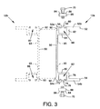
- FIG. 3 is an end view showing one beam in solid lines and a similarly constructed beam in dashed lines;
- FIG. 4 is an isometric view of a pivotable panel support node fixture
- FIG. 5 is a side view of a pivotable panel support node fixture
- FIG. 6 is an end view of a pivotable panel support node fixture
- FIG. 7 is an isometric view of a pivotable beam support fixture
- FIG. 8 is a side view of a pivotable beam support fixture
- FIG. 9 is an end view of a pivotable beam support fixture
- FIG. 10 is an end view of a beam showing the engagement of a pivotable panel support node fixture and a pivotable beam support fixture thereto;
- FIGS. 11 and 12 are side views of the structure supporting the beams in various configurations
- FIG. 13 is an exploded isometric view showing the relationship of a fixed connector and a threaded receptor socket to the upper region of a positionable support post;
- FIG. 14 is a partially exploded cross section view of the components of FIG. 13 ;
- FIG. 15 is a cross section view showing engagement of a fixed connector by a threaded receptor socket in the top of a positionable support post;
- FIG. 16 is an isometric view showing the relationship of an adjustable connector and a threaded receptor socket to the upper region of a positionable support post;
- FIG. 17 is a partially exploded cross section view of the components of FIG. 16 ;
- FIG. 18 is a cross section view showing engagement of an adjustable connector by a threaded receptor socket in the top of a positionable support post and by the top of the positionable support post;
- FIG. 19 is an isometric view showing a screw jack connector
- FIG. 20 is a partially exploded cross section view of the components of a screw jack connector in spaced alignment with the bottom portion of a stationary support post;
- FIG. 21 is a partial cross section view showing a screw jack and the relationship of a screw jack threaded shaft with a screw jack connector, the bottom of a stationary support post, a screw jack adjustment handle and screw jack boss, and a baseplate;
- FIG. 22 is an isometric view of one of the post connectors
- FIG. 23 is a cross section view of one of the post connectors, such as shown in use in FIG. 12 ;
- FIG. 24 is a cross section view of one of the adjustable foot support posts previously shown in use in FIGS. 11 and 12 ;
- FIG. 25 is a side view showing one configuration of the multipurpose adjustable panel system, such as shown in FIG. 12 , which can also incorporate a rear vertically oriented panel;
- FIG. 26 is a side view showing an extended configuration of the multipurpose adjustable panel system similar in many respects to the configuration shown in FIGS. 12 and 25 ;
- FIG. 27 is an isometric view of a level configuration of a multipurpose adjustable panel system similar in many respects to the configuration shown in FIG. 11 ;
- FIG. 28 is a side view of the level configuration of the multipurpose adjustable panel system of FIG. 27 ;
- FIG. 29 is a side view in partial cross section illustrating the use of various components of the present invention, including the use of mated beams and a plurality of platform panels and other associated components to serve and function as a cover having robust supportive qualities;
- FIG. 30 is an isometric view of a set of mated beams, oriented in the fashion depicted in FIG. 3 , along with one of two suspension assemblies located at the ends of the mated beams for contacting and resting upon the lip(s) of a swimming pool or upon portions of other structures;
- FIG. 31 is an end view in partial cross section illustrating the use of various components of the present invention, including the use of sets of mated beams and a plurality of platform panels and other associated components to serve and function as a cover;
- FIG. 32 is a cross section view of the mated beams of FIG. 30 showing the relationship of the node plate and nodes, the beams, the plate, the receptor fixtures, the platform panels, and other components to each other; and,
- FIG. 33 is a top view showing a plurality of platform panels supported over a swimming pool by sets of mated beams.
- FIG. 1 is an isometric view of a multipurpose adjustable panel system 10 , the present invention.
- Central to the invention are geometrically configured symmetrically shaped beams 12 a and 12 b aligned in opposition, the beams 12 a and 12 b and closely associated fixtures being capable of orientation and utilization in more than one angular or inclined position at different pitches and/or in various combinations to provide for maximum usefulness incorporating the components of the multipurpose adjustable panel system.
- Also central to the invention are a plurality of like pivotable panel support node fixtures 14 which are slidingly positionable along and fixably engaged in slots in the upper regions of the beams 12 a and 12 b , as later described in detail.
- Node receptor fixtures shown later in detail, located under the corners 16 a and 16 b of a plurality of platform panels 18 , align to the appropriate pivotable panel support node fixtures 14 in the slots in the upper regions of the beams 12 a and 12 b .
- Adjustable foot support posts shown in FIGS. 11 , 12 and 24 , are located under the corners 16 c and 16 d of the platform panels 18 .
- the platform panels 18 can be constructed according to the teachings regarding composite lightweight construction set forth in connection with those panels disclosed in U.S. Pat. No. 5,935,675 held by the assignee, and can include multiple recesses located on each platform panel underside for alignment to platform panel support nodes.
- a plurality of like pivotable beam support fixtures 20 which are slidingly positionable along and fixedly engaged in slots in the lower regions of the beams 12 a and 12 b , as later described in detail.
- Rearwardly placed and forwardly placed groups of support post assemblies 22 a , 22 b , 22 c and 22 d having vertical adjustability are incorporated for support of the beams 12 a and 12 b and associated overlying components.
- the support post assemblies 22 a , 22 b , 22 c and 22 d are similarly constructed, each including a stationary support post 24 and a positionable support post 26 slidingly accommodated within the stationary support post 24 and positionally fixed therein by the use of locking pins extending therethrough.
- the stationary support posts 24 and the adjustable support posts 26 are fabricated of, but not limited to, round tubular aluminum or other suitable lightweight material; but the use of other shapes of support posts and other closely related or connected components is within the scope of the invention.
- Interconnect tubes 28 , 30 and 32 secure and extend between the stationary support posts 24 of the support post assemblies 22 a and 22 b , and like interconnect tubes 28 , 30 and 32 secure and extend between the stationary support posts 24 of the support post assemblies 22 c and 22 d .
- Cross braces 34 , 36 , 38 and 40 having end couplers, extend and secure between the interconnect tubes 28 and 32 of the support post assemblies 22 a and 22 b and the support post assemblies 22 c and 22 d , as shown.
- Various connectors and other closely associated components including, but not limited to, fixed connectors 42 , adjustable connectors 44 , and screw jack connectors 46 , shown in FIG. 1 , are also shown in FIG. 11 and following figures in close and various associations with the upper ends of the positionable support posts 26 and/or with the lower ends of the stationary support posts 24 .
- FIG. 2 is an isometric view of one end of the beam 12 a , a pivotable panel support node fixture 14 aligned with the upper portion of the beam 12 a , and a pivotable beam support fixture 20 aligned with the lower portion of the beam 12 a ; and
- FIG. 3 is an end view showing the beam 12 a in solid lines and the beam 12 b in dashed lines.
- the beam 12 a preferably extruded of a lightweight material such as, but not restricted to, aluminum, includes a panel 50 and bifurcated support panels 52 and 54 extending perpendicularly from the top and bottom of the panel 50 .
- the bifurcated support panel 52 includes a panel section 52 a and a panel section 52 b separated by a contact track 56 at one edge of the panel section 52 a , a contact track 58 at one edge of the panel section 52 b in opposition to the contact track 56 , and a space 60 between the contact tracks 56 and 58 .
- a panel 62 intersects and extends perpendicularly from the panel section 52 b from a location in close proximity to the contact track 58 to intersect a panel 64 which extends perpendicularly from the panel 50 .
- a geometrically configured slot 66 is formed by close association of the contact track 58 , the panel 62 , the panel 64 , the upper portion of the panel 50 , the contact track 56 , and the space 60 for accommodation of one or more unistrut nuts 68 and accompanying bolts 70 which are incorporated to secure the pivotable panel support node fixtures 14 along the slot 66 .
- another slot 82 is located in opposition to the slot 66 .
- the bifurcated support panel 54 includes a panel section 54 a and a panel section 54 b separated by a contact track 72 at one edge of the panel section 54 a , a contact track 74 at one edge of the panel section 54 b in opposition to the contact track 72 , and a space 76 between the contact tracks 72 and 74 .
- a panel 78 intersects and extends perpendicularly from the panel section 54 b from a location in close proximity to the contact track 74 to intersect a panel 80 which extends perpendicularly from the panel 50 .
- the geometrically configured slot 82 is formed by close association of the contact track 74 , the panel 78 , the panel 80 , the lower portion of the panel 50 , the contact track 72 , and the space 76 for accommodation of one or more unistrut nuts 68 and accompanying bolts 70 which are incorporated to secure the pivotable beam support fixtures 20 along the slot 82 .
- the unistrut nuts 68 include parallel aligned grooves 84 and 86 on one surface and a centrally located threaded hole 88 for threaded accommodation of the bolts 70 .
- the parallel aligned grooves 84 and 86 of the unistrut nuts 68 intimately and frictionally engage the contact tracks 56 and 58 of the slot 66 by the tightening action of the bolts 70 extending through the pivotable panel support node fixture 14 in order to secure the pivotable panel support node fixture 14 to the bifurcated support panel 52 of the beam 12 a or 12 b , as shown in FIG. 10 .
- the parallel aligned grooves 84 and 86 of the unistrut nuts 68 intimately and frictionally engage the contact tracks 72 and 74 of the slot 82 by the tightening action of the bolts 68 extending through the pivotable beam support fixture 20 in order to secure the pivotable beam support fixture 20 to the bifurcated support panel 54 of the beam 12 a or 12 b , as shown in FIG. 10 .
- the last thread at the extreme end of each bolt 70 may be purposely damaged after suitable extension through the holes 88 of the unistrut nuts 68 to prevent mutual separation in order to keep such components together as required.
- a groove 90 extends inwardly along the junction of the panel 50 and the panel section 52 a of the bifurcated support panel 52 in close proximity to the slot 66
- a projection 92 extends outwardly from and along the outer face of the panel 50 near the junction of the panel 50 and the panel section 54 a in close proximity to the slot 82 .
- FIG. 3 is an end view showing in solid lines the beam 12 a and in dashed lines a similarly constructed beam 12 b positioned to be accommodatingly mated to the beam 12 a .
- formations similar to tongue and groove constructions can be utilized to position the beams.
- groove 90 of the beam 12 a can be accommodated by and aligned about the projection 92 of the beam 12 b
- the groove 90 of the beam 12 b can be accommodated by and aligned about the projection 92 of the beam 12 a when the vertically aligned panels 50 of the beams 12 a and 12 b are brought into and secured in intimate contact.
- a plurality of holes 93 are located along the panels 50 for fastening of the beams 12 a and 12 b together, as required. Such an option makes such a combination useful for heavy loading, if required, and is also useful in related applications of the components of the invention for use as described later in detail with reference to FIGS. 29 , 30 , 31 , 32 and 33 .
- FIG. 4 is an isometric view of a pivotable panel support node fixture 14 ;
- FIG. 5 is a side view of the pivotable panel support node fixture 14 ;
- FIG. 6 is an end view of the pivotable panel support node fixture 14 .
- the pivotable panel support node fixture 14 includes a baseplate 94 having elongated holes 96 and 98 offset from the center thereof for accommodation of bolts 70 which are used to engage unistrut nuts 68 to the underside of the baseplate 94 .
- Spaced and paired pivot mounts 100 and 102 having holes 101 and 103 , respectively, and spaced and paired pivot mounts 104 and 106 having holes 105 and 107 , respectively, are secured such as by welding to the upper midportion of the baseplate 94 .
- Pivot plates 108 and 110 having holes 109 and 111 , respectively, are secured such as by welding to the underside of a node plate 112 in interspersed alignment between the spaced and paired pivot mounts 100 and 102 and spaced and paired pivot mounts 104 and 106 .
- a pivot bolt 114 extends through holes 101 and 103 in the spaced and paired pivot mounts 100 and 102 , through holes 105 and 107 in the spaced and paired pivot mounts 104 and 106 , and through holes 109 and 111 in the pivot plates 108 and 110 to pivotally connect the baseplate 94 to the node plate 112 .
- a nut 115 is included for engagement of the threaded end of the pivot bolt 114 .
- a plurality of support nodes 116 are suitably located and fastened to the upper side of the node plate 112 .
- the pivotable panel support node fixtures 14 can be slidingly positioned along the bifurcated support panel 52 , wherein the slot 66 of the beam 12 a or 12 b offers guidance therealong using the unistrut nuts 68 and bolts 70 to track along the slot 66 .
- the unistrut nuts 68 and bolts 70 can be tightened to positionally secure the pivotable panel support node fixtures 14 to the bifurcated support panel 52 of the beam 12 a or 12 b .
- the node plate 112 including the plurality of support nodes 116 , is free to rotate about the pivot bolt 114 , as demonstrated in FIG. 5 , thereby accommodating angular differences between the pitch of the beams 12 a and 12 b , which can be different in various configurations, and the preferably level pitch of the platform panels 18 .
- FIG. 7 is an isometric view of a pivotable beam support fixture 20 ;
- FIG. 8 is a side view of the pivotable beam support fixture 20 ;
- FIG. 9 is an end view of the pivotable beam support fixture 20 .
- the pivotable beam support fixture 20 includes a baseplate 118 having slots 120 and 122 at opposing edges and a hole 124 , wherein the slots 120 and 122 and the hole 124 are offset from the center thereof and utilized for accommodation of bolts 70 used to fasten unistrut nuts 68 to the upperside of the baseplate 118 .
- a bolt 70 extends through the hole 124 and through the threaded hole 88 of the unistrut nut 68 to position the unistrut nut 68 on the upperside of the baseplate 118 for subsequent accommodation by the slots 82 of the beams 12 a and 12 b .
- Bolts 70 extend accommodatingly through the slots 120 and 122 for the same purpose after gaining direct access vertically through the slots 120 and/or 122 or after gaining sideways or sliding entry into the slots 120 and/or 122 to pass through the threaded holes 88 of the associated unistrut nuts 68 to position the unistrut nuts 68 on the upperside of the baseplate 118 for subsequent accommodation by the slots 82 of the beams 12 a and 12 b .
- Such an arrangement using the slots 120 and 122 allows for sliding versatility during initial positioning of the pivotable beam support fixture 20 , as desired, to minimize jamming of the unistrut nuts 68 within the slots 82 of the beams 12 a and 12 b .
- the outboard unistrut nuts 68 and accompanying bolts 70 can be positioned in the slots 82 on both sides of, but not engaged within, the slots 120 and 122 of the baseplate 118 .
- the pivotable beam support fixture 20 can be slidingly positioned along the bifurcated support panel 54 of the beam 12 a or 12 b using the single unistrut nut 68 and bolt 70 aligned to the hole 124 to track along the slot 82 .
- the adjacently positioned unistrut nuts 68 and bolts 70 can be repositioned within and along the slot 82 to cause the bolts 70 to enteringly engage the slots 120 and 122 in the baseplate 118 , whereupon all the unistrut nuts 68 and bolts 70 can be tightened to positionally secure the pivotable beam support fixture to the bifurcated support panel 54 of the beam 12 a or 12 b .
- a guide bar 126 is also included at the outboard edge of the baseplate 118 .
- Opposed pivot mounts 128 and 130 having pivot holes 132 and 134 , respectively, are suitably secured such as by welding to the underside of the baseplate 118 for subsequent pivoted connection to the top of an adjustable connector 44 or fixed connector 42 at the upper regions of support post assemblies 22 a - 22 d.
- FIG. 10 is an end view of the beam 12 a showing the engagement of a pivotable panel support node fixture 14 and a pivotable beam support fixture 20 thereto. Shown in particular is the relationship of the pivotable panel support node fixture 14 to the bifurcated support panel 52 , wherein the baseplate 94 of the pivotable panel support node fixture 14 is in intimate, supported and secured contact with the bifurcated support panel 52 .
- the pivotable panel support node fixture 14 Prior to securing of the pivotable panel support node fixture 14 to the bifurcated support panel 52 , the pivotable panel support node fixture 14 is positioned, as desired, along the bifurcated support panel 52 , during which time the shafts of the bolts 70 are slidingly accommodated by and traverse along the space 60 between the contact tracks 56 and 58 and a portion of the slot 66 , and during which time the unistrut nut 68 is slidingly accommodated by and traverses along the slot 66 .
- the shafts of the bolts 70 pass through the slotted holes 96 and 98 of the baseplate 94 to engage the threads of the threaded holes 88 of the unistrut nuts 68 , and the heads of the bolts 70 engage the portion of the baseplate 94 surrounding the elongated holes 96 and 98 .
- the sides of the unistrut nuts 68 are in close proximity with the panel 62 and an opposite portion of the panel 50 and are prevented from rotation during tightening by such an arrangement.
- the grooves 84 and 86 of the unistrut nuts 68 are brought into forcible frictional engagement with the contact tracks 56 and 58 , respectively, thereby forcing the baseplate 94 of the pivotable panel support node fixture 14 into supported frictional engagement with the bifurcated support panel 52 , thereby providing stable and locked engagement thereto.
- the baseplate 118 of the pivotable beam support fixture 20 enjoys a similar and closely related association, wherein the bolts 70 and unistrut nuts 68 are utilized in a fashion as just described and as previously described collectively with respect to FIGS.
- the locking pin 136 passes through the holes 132 and 134 of the pivot mounts 128 and 130 , respectively, as well as through opposed holes in a structure, such as, but not limited to, the upper (or other) region of a fixed connector 42 or of an adjustable connector 44 , wherein the detent ball 142 extends beyond the outer portion of a hole and extends outwardly to ensure capture of the locking pin 136 .
- FIGS. 11 and 12 are side views of the structure supporting the beams 12 a and 12 b where the beams 12 a and 12 b are inclined or pitched, such as for use as support for seating; but the arrangement of all or most of the components can also result where the beams 12 a and 12 b are level instead of being inclined to provide level elevated or non-elevated platforms. More specifically, the location and interconnecting relationship of the components of the instant invention used in various inclined or pitched arrangements is shown in FIGS. 11 and 12 . FIG.
- FIG. 11 shows elevation of one end of the beam 12 a by a single level of support post assemblies 22 a and 22 b and closely associated components, such as, but not limited to, a pivotable beam support fixture 20 secured to the bifurcated support panel 54 on the underside of the beam 12 a , as previously described, in alignment with an adjustable connector 44 secured to the pivotable beam support fixture 20 , such as by a locking pin 136 , the top of the positionable support post 26 of the support post assembly 22 a being engaged and secured to the bottom of the adjustable connector 44 , and the bottom of the positionable support post 26 shown telescopingly engaging and extending above the interior of the stationary support post 24 of the support post assembly 22 a and secured therein by a locking pin 136 , a screw jack 137 comprised of a screw jack connector 46 secured to the bottom of the stationary support post 24 , a screw jack boss 148 including a screw jack adjustment handle 150 engaging the bottom of the screw jack connector 46 , a screw jack threaded shaft
- the support post assembly 22 b and closely associated components are arranged and constructed in a similar fashion to the support post assembly 22 a and closely associated components but include a fixed connector 42 at the upper end of the positionable support post 26 in lieu of the adjustable connector 44 .
- the support post assemblies 22 a and 22 c and closely associated components are arranged and constructed in a fashion similar to one another and the support post assemblies 22 b and 22 d and closely associated components are arranged and constructed in a fashion similar to one another.
- the pivotable panel support node fixtures 14 are shown secured to the bifurcated support panel 52 at the upper portion of the beam 12 a , wherein support for the corners 16 a of the platform panels 18 is provided by a node receptor fixture 154 located in the undersides of the corners 16 a .
- Adjustable foot support posts 146 which can be of various lengths, secure opposite to the receptor fixtures 154 in the undersides of the corners 16 c (and 16 d ).
- the adjustable foot support posts 146 are incorporated to provide adjustable support for one end of the platform panels 18 .
- FIG. 12 shows elevation of one end of the beam 12 a at a greater pitch than that of the beam 12 a shown in FIG. 11 by an additional level of support post assemblies like support post assemblies 12 a and 12 b , herein designated as support post assemblies 22 aa and 22 bb , and for the most, like closely associated components at a location stacked atop the support post assemblies 22 a and 22 b and closely associated components.
- the adjustable connectors 44 are removed from the tops of the positionable support posts 26 of the support post assemblies 22 a and 22 b and replaced by post connectors 144 which secure to the tops of the positionable support posts 26 .
- the bottoms of the stationary support posts 24 of the support post assemblies 22 aa and 22 bb are accommodated by the post connectors 144 at the tops of the positionable support posts 26 of the support post assemblies 22 a and 22 b .
- Positional versatility is provided considering the adjustment along or in combination with the jack screws 137 at the lower ends of the stationary support posts 24 , where applicable, the vertical stacking and adjustability of the support post assemblies 22 a , 22 b , 22 aa and 22 bb and other like assemblies, the vertical adjustability of the adjustable connectors 44 , and the pivotability of the pivotable panel support node fixtures 14 and the pivotable beam support fixtures 20 .
- Features of the connector devices are included and described in detail in connection with FIGS. 13-24 .
- FIG. 13 is an exploded isometric view showing the relationship of a fixed connector 42 and a threaded receptor socket 156 to the upper region of a positionable support post 26 ;
- FIG. 14 is a partially exploded cross section view of the components of FIG. 13 ;
- FIG. 15 is a cross section view showing engagement of the fixed connector 42 by the threaded receptor socket 156 in the top of the positionable support post 26 .
- Each of the one-piece threaded receptor sockets 156 is of multiple radius construction, wherein a lesser radius plug 158 of cylindrical form extends from a larger radius annular shoulder 160 .
- a centrally located threaded hole 162 aligns along the central axis.
- Transversely aligned holes 164 and 165 extend into the plug 158 short of the threaded hole 162 for partial accommodation of roll pins 166
- an interrupted transversely aligned hole 168 extends through the upper region of the positionable support post 26 in intersection with the bore 170 for partial accommodation of roll pins 166 in order to secure the threaded receptor socket 156 in the bore 170 of the upper region of the positionable support post 26 .
- Each fixed connector 42 includes a cylinder 172 suitably secured, such as by welding, to a disk-shaped base 174 .
- a threaded shaft 176 can be threaded into a threaded hole 178 in the disk-shaped base 174 or, alternatively, the threaded shaft 176 can be aligned within an unthreaded similarly located hole central to the disk-shaped base 174 and secured therein by welding or other suitable means.
- a plurality of transversely aligned and opposed holes 180 are included in the cylinder 172 for accommodation of a locking pin 136 , such as when connected to the lower portion of a pivotable beam support fixture 20 .
- the cylinder 172 , the base 174 , and the threaded shaft 176 could be combined using various combinations into a unitary one-piece structure.
- the threaded shafts 176 of the fixed connectors 42 engage the threaded holes 162 of the threaded receptor sockets 156 and are rotated to cause intimate and planar engagement of the bases 174 of the fixed connectors 42 to the tops of the threaded receptor sockets 156 , thereby offering a suitable and stable association therebetween.
- FIG. 16 is an isometric view showing the relationship of an adjustable connector 44 and a threaded receptor socket 156 to the upper region of a positionable support post 26 ;
- FIG. 17 is a partially exploded cross section view of the components of FIG. 16 ;
- FIG. 18 is a cross section view showing engagement of the adjustable connector 44 by the threaded receptor socket 156 in the top of the positionable support post 26 and by the top of the positionable support post 26 .
- each adjustable connector 44 includes a cap 182 having a cylinder 184 , a circular plate 186 suitably secured, such as by welding, to the upper portion of the cylinder 184 , and a threaded shaft 188 .
- the threaded shaft 188 which extends into and along the centerline of the bore 190 of the cylinder 184 , can be threaded into a threaded hole 192 in the circular plate 186 or, alternatively, the threaded shaft 188 can be aligned within an unthreaded similarly located hole central to the circular plate 186 and secured therein by welding or other suitable means.
- a plurality of threaded holes 194 distributed about the lower portion of the cylinder 184 , accommodate a plurality of thumbscrews 196 which can rotatingly extend into the bore 190 to engage an upper portion of a positionable support post 26 .
- a robust threaded shaft 198 is aligned along and about the centerline of the adjustable connector 44 and is suitably secured, such as by welding, to the outer planar surface of the circular plate 186 from which it extends to threadingly engage the threads 200 of a robust nut 202 suitably secured, such as by welding, to the lower region of a cylinder 204 .
- the threaded shaft 198 extends beyond the nut 202 into the bore 206 of the cylinder 204 .
- the components of the cap 182 including the cylinder 184 , the circular plate 186 , the threaded shaft 188 , and additionally including the threaded shaft 198 , could be combined using various combinations into a unitary one-piece structure.
- a plurality of transversely aligned and opposed holes 208 are included at the upper region of the cylinder 204 for accommodation of a locking pin 136 , such as when connected to the lower portion of a pivotable beam support fixture 20 .
- adjustable connectors 44 Use of the adjustable connectors 44 is initiated by placing the cap 182 portion of the adjustable connector 44 over the upper region of the combined threaded receptor socket 156 and top of the positionable support post 26 and rotating the cap 182 and connected components to cause the threaded shaft 188 to engage the threaded hole 162 of the threaded receptor socket 156 , and thence continuing rotation to cause intimate and planar engagement of the circular plate 186 of the cap 182 with the top of the threaded receptor socket 156 , thereby offering a suitable and stable well-connected association therebetween.
- the thumbscrews 196 can be rotated to engage an upper portion of the positionable support post 26 for additional stability and connection.
- the cylinder 204 is vertically and rotatably adjustable along and about the threaded shaft 198 in order to align to the lower portion of a pivotable beam support fixture 20 for suitable connection thereto.
- FIG. 19 is an isometric view showing a screw jack connector 46 which is part of the screw jack 137 ;
- FIG. 20 is a partially exploded cross section view of the components of the screw jack connector 46 in spaced alignment with the bottom portion of a stationary support post 24 ;
- FIG. 21 is a partial cross section view showing the screw jack 137 and the relationship of the screw jack threaded shaft 152 with the screw jack connector 46 , the bottom of a stationary support post 24 , a screw jack adjustment handle 150 and screw jack boss 148 , and a baseplate 48 .
- Each of the screw jack connectors 46 includes a cylinder 210 suitably secured, such as by welding, to a receptor socket 212 , wherein the structure of the receptor socket 212 , as shown in FIGS. 19 and 20 , is similar in many respects to the structure of the threaded receptor socket 156 , previously shown.
- Each of the one-piece receptor sockets 212 is of multiple radius construction, wherein a reduced radius plug 214 of cylindrical form extends from a larger radius annular shoulder 216 .
- a centrally located hole 218 having a smooth surface aligns along the central axis of the one-piece receptor socket 212 .
- the reduced radius plug 214 is sized to form an annulus 220 between the reduced radius plug 214 and the inside wall of the cylinder 210 for accommodation of the bottom portion of a stationary support post 24 .
- a keeper assembly 222 is located on the side of the cylinder 210 , and includes a keeper body 224 , which can be tubular, a shouldered keeper pin 226 aligned generally within and along the interior of the keeper body 224 and extending a short distance into the open main portion of the bore 228 of the cylinder 210 and extending through a hole in an end plate 234 at the end of the keeper body 224 , a spring 230 aligned over and about a portion of the keeper pin 226 in contact with a shoulder 232 of the keeper pin 226 and in contact with the end plate 234 at the end of the keeper body 224 , and a grasping ring 236 extending through the outboard end of the keeper pin 226 .
- the stationary support post 24 includes a bore 238 which is accommodated by the outer and annular surface of the plug 214 .
- the lower portion of the stationary support post 24 aligns generally within the bore 228 of the cylinder 210 and within the annulus 220 between the receptor socket 212 and the cylinder 210 .
- a hole 240 in the lower portion of the stationary support post 24 aligns to the inboard end of the keeper pin 226 , which is spring-loaded inwardly, to secure the screw jack connector 46 , and thus the screw jack 137 , to the lower portion of the stationary support post 24 .
- FIG. 21 the components of FIGS. 19 and 20 are shown in engagement with the other components of the screw jack 137 , and more particularly, with a screw jack threaded shaft 152 , a screw jack adjustment handle 150 , a screw jack boss 148 , and the baseplate 48 .
- the screw jack threaded shaft 152 secures to and extends from the baseplate 48 through the interior threads of the screw jack boss 148 , through the hole 218 of the receptor socket 212 , and thence into the bore 238 of the stationary support post 24 .
- the lower portion of the receptor socket 212 at the lower region of the screw jack connector 46 bears upon the upper surface of the screw jack boss 148 , wherein the screw jack boss 148 is operated along and about the screw jack threaded shaft 152 by action of the screw jack adjustment handle 150 to vertically adjust the level of the stationary support post 24 and the components engaging the stationary support post 24 .
- FIG. 22 is an isometric view of one of the post connectors 144 ; and FIG. 23 is a cross section view of one of the post connectors 144 , such as shown in use in FIG. 12 to connect the bottom of stationary support posts 24 of the upper support post assemblies 22 aa and 22 bb to the positionable lower support posts 26 of the support post assemblies 22 a and 22 b .
- Each of the post connectors 144 includes a cylinder 242 suitably secured, such as by welding, to a disk-shaped base 244 .
- a threaded shaft 246 can be threaded into a threaded hole 248 in the disk-shaped base 244 or, alternatively, the threaded shaft 246 can be aligned within an unthreaded similarly located hole central to the disk-shaped base 244 and secured therein by welding or other suitable means.
- the bore 250 of the cylinder 242 is incorporated to accommodate the lower portion of a stationary support post 24 .
- the threaded shafts 246 of the post connectors 144 engage the threaded holes 162 of the threaded receptor sockets 156 located in the tops of the positionable support posts 26 of the lower support post assemblies 22 a and 22 b and are rotated to intimately and planarly engage the bases 244 of the post connectors 144 to the tops of the threaded receptor sockets 156 , thereby offering a suitable and stable association therebetween.
- the cylinder 242 , the disk-shaped base 244 , and the threaded shaft 246 could be combined using various combinations into a unitary one-piece structure.
- FIG. 24 is a cross section view of one of the adjustable foot support posts 146 previously shown in use in FIGS. 11 and 12 .
- the adjustable foot support post 146 includes a cylinder 252 , which can be of various lengths, as required, and a previously described threaded receptor socket 156 (which can be of reduced size) which secures in the bore 253 of the cylinder 252 using holes 254 and 256 in the lower portion of the cylinder 252 aligned to the holes 164 and 165 of the threaded receptor socket 156 into which extend roll pins 166 .
- a threaded shaft 258 securing into an adjustment nut 260 engages the threads of the threaded hole 162 of the threaded receptor socket 156 and includes a tip 262 of suitable material, such as, but not limited to, rubber, plastic, or the like located at one side of the adjustment nut 260 .
- FIG. 25 is a side view showing one configuration of the multipurpose adjustable panel system 10 , such as shown in FIG. 12 , which can also incorporate a rear vertically oriented panel 266 .
- a great degree of versatile adjustability is incorporated into the structure of the invention.
- a first example of adjustability involves the combined vertical slidable telescoping relationship of the components of the rearwardly placed and forwardly placed groups of support post assemblies 22 a , 22 b , 22 c and 22 d , as well as corresponding stacked groups of support post assemblies 22 aa , 22 bb , 22 cc and 22 dd , of which the latter two of each group are not shown for purposes of brevity and clarity.
- Also involved as part of the first example of adjustability is the coordinated near simultaneous horizontal spacing adjustment of the components of the rearwardly placed and forwardly placed groups of support post assemblies 22 a , 22 b , 22 c and 22 d , as well as corresponding stacked groups of support post assemblies 22 aa , 22 bb , 22 cc and 22 dd along the beams 12 a and 12 b .
- the stationary support posts 24 slidingly accommodate the positionable support posts 26 within the interiors of the stationary support posts 24 , and the positionable support posts 26 are fixed therein by the use of locking pins 136 extending therethrough in use as part of a first adjustment, wherein the positionable support posts 26 having fixed connectors 42 are positioned to nearly achieve the required pitch of the beams 12 a and 12 b . Then, the spacing of the groups of forwardly and rearwardly placed groups of support post assemblies mentioned above can be varied along the beams 12 a and 12 b to additionally affect the pitch of the beams 12 a and 12 b to accomplish the remainder of the first adjustability example.
- pivotable beam support fixtures 20 The ability of the pivotable beam support fixtures 20 to be horizontally spaced at various distances is fostered by the ability of the pivotable beam support fixtures 20 to accommodatingly slide along the lower slot 82 of the beams 12 a and 12 b . Such allows readily accomplished setup.
- the combination of vertical adjustment of the support post assemblies, as well as the horizontal spacing of the groups of support post assemblies, provides for continuous pitch adjustability of the beams 12 a and 12 b.
- a second vertically adjusted support feature is provided by the use of the adjustable connectors 44 between the top of other positionable support posts 26 and the pivotable beam support fixtures 20 , such as in the support post assemblies 22 a , 22 aa , 22 c and 22 cc , where the adjustable connectors 44 are adjusted to provide additional support of the beams 12 a and 12 b .
- the positionable support posts 26 and the adjustable connectors 44 atop the positionable support posts 26 can then suitably be adjusted upwardly in order to connect the adjustable connectors 44 to the pivotable beam support fixtures 20 by the use of locking pins 136 .
- the adjustable connectors 44 can be adjusted after connection to the pivotable beam support fixtures 20 .
- a third vertical adjustment at the bottom of each of the ground level stationary support posts 24 is provided by the use of the screw jack 137 incorporating the screw jack connector 46 , the screw jack boss 148 , the screw jack adjustment handle 150 , the screw jack threaded shaft 152 , and the baseplate 48 .
- the various combinations of these adjustments provide a continuous adjustability pitch range, as well as provide for overall elevation accommodation on any regular or irregular surface.
- the multiple vertical adjustment capability in concert with other key components addresses geometric configurations both vertically and horizontally.
- the use of beams 12 a and 12 b each having a slot 82 and a bifurcated support panel 54 allows the pivotable beam support fixtures 20 to be slidably positioned, as required, along the slots 82 and bifurcated support panels 54 to any desirable position along the beams 12 a and 12 b to facilitate appropriately pitched direct support of the beams 12 a and 12 b by the components connected to and by the support post assemblies 22 a , 22 b , 22 c and 22 d , as well as corresponding stacked groups of support post assemblies 22 aa , 22 bb , 22 cc and 22 dd atop support post assemblies 22 a , 22 b , 22 c and 22 d .
- the pivotable beam support fixtures 20 are free to pivot in response to the adjustment of the pitch of the beams 12 a and 12 b .
- the position of the pivotable beam support fixtures 20 is securely fixed along the slots 82 and the bifurcated support panels 54 by ensuring that the slots 120 and 122 of the pivotable beam support fixtures 20 each accommodates a bolt 70 and connected unistrut nut 68 followed by tightening of all of the bolts 70 to cause the unistrut nuts 68 to tighten in the slots 82 , as previously described.
- the platform panels 18 can be installed on the upper portions of the beams 12 a and 12 b via the pivotable panel support node fixtures 14 .
- the spacing change between the pivotable panel support node fixtures 14 along the topsides of the beams 12 a and 12 b are accommodated by the slots 66 which offer continuous locational positions for the pivotable panel support node fixtures 14 .
- the unistrut nuts 68 which connect to the undersides of the baseplates 94 of the pivotable panel support node fixtures 14 by bolts 70 engage the slots 66 at the upper region of the beams 12 a and 12 b and can be positionably slid therealong to position the pivotable panel support node fixtures 14 at any suitable location along the lengths of the bifurcated support panels 52 , whereupon the bolts 70 are tightened to utilize the unistrut nuts 68 to secure the pivotable panel support node fixtures 14 thereto.
- Node receptor fixtures 154 on the undersides of corners 16 a and 16 b of the platform panels 18 are aligned to one or more of the support nodes 116 on the node plates 112 of the pivotable panel support node fixtures 14 followed by adjustment of the adjustable foot support posts 146 at the undersides of the corners 16 c and 16 d which rest upon the upper surfaces of successive lower platform panels 18 to achieve leveling of the platform panels 18 .
- the node plates 112 of the pivotable panel support node fixtures 14 are accommodatingly free to pivot, thereby making the installation process at the end having the pivotable panel support node fixtures 14 self-adjusting.
- the lowermost platform panel 18 at the end of a series of platform panels 18 can be accommodated in several ways.
- the multipurpose adjustable panel system 10 can be situated at a level lower than an existing structure 264 , such as a stage, a playing field, an access walkway, or the like, and, as such, the lower platform panel 18 incorporates an attached adjustable foot support post 146 for support on the existing structure 264 .
- an extended adjustable foot support post 146 a can be substituted for the adjustable foot support post 146 at the outboard end of the lower platform panel 18 , the position of which is shown by a dashed line.
- FIG. 26 is a side view showing an extended configuration of the multipurpose adjustable panel system 10 , similar in many respects to the configuration shown in FIGS. 12 and 25 .
- An additional beam 12 aa (and 12 bb , not shown) is connected to and extends from the lower ends of the beams 12 a and 12 b extending beyond the forwardly placed support post assemblies 22 a , 22 b , 22 c and 22 d to a position near a supporting surface where additional support is provided by pivotable beam support fixtures 20 , adjustable connectors 44 , nuts 202 , threaded shaft 198 , and baseplates 48 .
- An additional platform panel 18 at the ground level is supported by multiple adjustable foot support posts 146 .
- FIG. 27 is an isometric view of a level configuration of a multipurpose adjustable panel system 10 , similar in many respects to the configuration shown in FIG. 11 ; and FIG. 28 is a side view of the level configuration of the multipurpose adjustable panel system 10 of FIG. 27 .
- the components closely associated with the support post assemblies 22 a , 22 b , 22 c and 22 d are adjusted vertically to cause the beams 12 a and 12 b to be level and to have no incline or pitch, and the adjustable foot support posts 146 are not utilized.
- each of the positionable support posts 26 can include a fixed connector 42 at the top portion thereof in lieu of an adjustable connector 44 , as the use of an appropriate amount of adjustable connectors 44 is required when the beams 12 a and 12 b are required to maintain an incline or pitch other than a zero pitch.
- adjustable connectors 44 can be used exclusively, if desired.
- Each of the corners 16 a - 16 d of the platform panels 18 can engage one or more support nodes 116 of the pivotable panel support node fixtures 14 .
- the platform panels 18 are arranged adjacent to one another to present a flat planar surface which is elevated and which is suitable for multiple purposes, such as, but not limited to, use as a support for level seating, staging, workers working on an overhead project, for example, or any other situation requiring the use of an elevated platform.
- the platform panels 18 illustrated in FIG. 27 are shown engaging only some of the support nodes 116 of each pivotable panel support node fixture 14 , whereby the remaining support nodes 116 are available for accommodation of adjacently placed structures. For purposes of example and illustration, an additional structure, such as shown in FIG.
- additional beams such as beams 12 a and 12 b supported in the fashion as previously described, could be spaced from and added to both or either side of the structure shown in FIG. 27 , including additional cross braces 34 , 36 , 38 and 40 ; and platform panels 18 could be added and supported by the support nodes 116 of common pivotable panel support node fixtures 14 .
- FIG. 29 is a side view in partial cross section illustrating the use of various components of the present invention, including the use of mated beams 12 a and 12 b and a plurality of platform panels 18 and other associated components to serve and function as a cover having robust supportive qualities capable of supporting heavy snowfalls, animals treading thereupon, personnel walking thereupon, and the like.
- mated beams 12 a and 12 b and a plurality of platform panels 18 and other associated components to serve and function as a cover having robust supportive qualities capable of supporting heavy snowfalls, animals treading thereupon, personnel walking thereupon, and the like.
- the various components of the present invention could be incorporated to span open areas of partially completed construction sites, missing sidewalk spans, and other multiple undisclosed uses.
- FIG. 30 is an isometric view of a set of mated beams 12 a and 12 b , oriented in the fashion depicted in FIG. 3 , along with one of two suspension assemblies 270 , as also shown in FIG. 29 , incorporated at the ends of the mated beams 12 a and 12 b for contacting and resting upon the lip(s) 272 of the swimming pool 268 .
- a plurality of node plates 112 including a plurality of support nodes 116 affixed to the upper surfaces thereof, are secured to either of the slots 66 or 82 of the beams 12 a and/or 12 b , as appropriate, using a plurality of unistrut nuts 68 and bolts 70 .
- the support nodes 116 accommodate the node receptor fixtures 154 at the corners 16 a - 16 d of the platform panels 18 .
- a plurality of adjustable foot support posts 146 are utilized at the lower periphery of some of the platform panels 18 for support of the edges of the platform panels 18 .
- the suspension assemblies 270 include a vertically oriented plate 274 having a plurality of holes 276 which is aligned perpendicularly to and suitably secured, such as by welding, to another vertically aligned plate 278 to which a horizontally oriented stub beam 280 which can be comprised or two back-to-back channels is attached.
- the stub beam 280 can be of single I-beam construction aligned perpendicularly to and suitably secured, such as by welding, to the plate 278 .
- a plurality of holes 282 matching the holes 276 in the plate 274 of the suspension assembly 270 , are included at the ends of the beams 12 a and 12 b and are incorporated with the use of suitable fasteners (not shown), such as bolts and nut assemblies, rivets, and the like, extending therethrough, for fastening of the suspension assemblies 270 to the panels 50 of the beams 12 a and 12 b .
- suitable fasteners not shown
- a plurality of nut and bolt assemblies 284 extending through the holes 93 for fastening the beam 12 a to the beam 12 b.
- FIG. 31 is an end view in partial cross section illustrating the use of various components of the present invention, including the use of sets of mated beams 12 a and 12 b and a plurality of platform panels 18 and other associated components to serve and function as a cover.
- FIG. 32 is a cross section view of the mated beams 12 a and 12 b of FIG. 30 showing the relationship of the node plate 112 and support nodes 116 , the beams 12 a and 12 b , the plate 274 , the node receptor fixtures 154 , the platform panels 18 , and other components to each other.
- FIG. 33 is a top view showing a plurality of platform panels 18 aligned to and accommodated by a plurality of node plates 112 having support nodes 116 secured to the slots 66 and/or 82 of the mated beams 12 a and 12 b . Also shown is the alignment of the suspension assemblies 270 to the lips 272 of the swimming pool 268 . A plurality of adjustable foot support posts 146 are also shown supporting the outer edges of the platform panels 18 .
Landscapes
- Engineering & Computer Science (AREA)
- Architecture (AREA)
- Civil Engineering (AREA)
- Structural Engineering (AREA)
- Mechanical Engineering (AREA)
- Mutual Connection Of Rods And Tubes (AREA)
Abstract
Description
- 10 multipurpose adjustable panel system
- 12 a-b beams
- 12 aa beam
- 14 pivotable panel support node fixture
- 16 a-d corners
- 18 platform panel
- 20 pivotable beam support fixture
- 22 a-d support post assemblies
- 22 aa support post assembly
- 22 bb support post assembly
- 22 cc support post assembly
- 22 dd support post assembly
- 24 stationary support post
- 26 positionable support post
- 28 interconnect tube
- 30 interconnect tube
- 32 interconnect tube
- 34 cross brace
- 36 cross brace
- 38 cross brace
- 40 cross brace
- 42 fixed connector
- 44 adjustable connector
- 46 screw jack connector
- 48 baseplate
- 50 panel
- 52 bifurcated support panel
- 52 a-b panel sections
- 54 bifurcated support panel
- 54 a-b panel sections
- 56 contact track
- 58 contact track
- 60 space
- 62 panel
- 64 panel
- 66 slot
- 68 unistrut nut
- 70 bolt
- 72 contact track
- 74 contact track
- 76 space
- 78 panel
- 80 panel
- 82 slot
- 84 groove
- 86 groove
- 88 threaded hole
- 90 groove
- 92 projection
- 93 hole
- 94 baseplate
- 96 elongated hole
- 98 elongated hole
- 100 pivot mount
- 101 hole
- 102 pivot mount
- 103 hole
- 104 pivot mount
- 105 hole
- 106 pivot mount
- 107 hole
- 108 pivot plate
- 109 hole
- 110 pivot plate
- 111 hole
- 112 node plate
- 114 pivot bolt
- 115 nut
- 116 support node
- 118 baseplate
- 120 slot
- 122 slot
- 124 hole
- 126 guide bar
- 128 pivot mount
- 130 pivot mount
- 132 pivot hole
- 134 pivot hole
- 136 locking pin
- 137 screw jack
- 138 grasping ring
- 140 taper
- 142 detent ball
- 144 post connector
- 146 adjustable foot support post
- 146 a extended adjustable foot support post
- 148 screw jack boss
- 150 screw jack adjustment handle
- 152 screw jack threaded shaft
- 154 node receptor fixture
- 156 threaded receptor socket
- 158 plug
- 160 shoulder
- 162 threaded hole
- 164 hole
- 165 hole
- 166 roll pin
- 168 interrupted hole
- 170 bore
- 172 cylinder
- 174 base
- 176 threaded shaft
- 178 threaded hole
- 180 hole
- 182 cap
- 184 cylinder
- 186 circular plate
- 188 threaded shaft
- 190 bore
- 192 threaded hole
- 194 threaded hole
- 196 thumbscrew
- 198 threaded shaft
- 200 threads
- 202 nut
- 204 cylinder
- 206 bore
- 208 hole
- 210 cylinder
- 212 receptor socket
- 214 plug
- 216 shoulder
- 218 hole
- 220 annulus
- 222 keeper assembly
- 224 keeper body
- 226 keeper pin
- 228 bore
- 230 spring
- 232 shoulder
- 234 end plate
- 236 grasping ring
- 238 bore
- 240 hole
- 242 cylinder
- 244 base
- 246 threaded shaft
- 248 threaded hole
- 250 bore
- 252 cylinder
- 253 bore
- 254 hole
- 256 hole
- 258 threaded shaft
- 260 adjustment nut
- 262 tip
- 264 existing structure
- 266 rear vertically oriented panel
- 268 swimming pool
- 270 suspension assembly
- 272 lip
- 274 plate
- 276 holes
- 278 plate
- 280 stub beam
- 282 hole
- 284 nut and bolt assembly
Claims (30)
Priority Applications (1)
| Application Number | Priority Date | Filing Date | Title |
|---|---|---|---|
| US11/331,326 US7971395B1 (en) | 2006-01-12 | 2006-01-12 | Multipurpose adjustable panel system |
Applications Claiming Priority (1)
| Application Number | Priority Date | Filing Date | Title |
|---|---|---|---|
| US11/331,326 US7971395B1 (en) | 2006-01-12 | 2006-01-12 | Multipurpose adjustable panel system |
Publications (1)
| Publication Number | Publication Date |
|---|---|
| US7971395B1 true US7971395B1 (en) | 2011-07-05 |
Family
ID=44202311
Family Applications (1)
| Application Number | Title | Priority Date | Filing Date |
|---|---|---|---|
| US11/331,326 Expired - Fee Related US7971395B1 (en) | 2006-01-12 | 2006-01-12 | Multipurpose adjustable panel system |
Country Status (1)
| Country | Link |
|---|---|
| US (1) | US7971395B1 (en) |
Cited By (10)
| Publication number | Priority date | Publication date | Assignee | Title |
|---|---|---|---|---|
| US20140325925A1 (en) * | 2013-05-01 | 2014-11-06 | Comfort Zone Killer LLC | Modular Multipurpose Platform and Hardware |
| US20150033661A1 (en) * | 2013-07-31 | 2015-02-05 | Staging Concepts Acquisitions, Llc | Staging system and method |
| US9380760B2 (en) | 2012-11-02 | 2016-07-05 | Petedge, Inc. | Folding pet ramp and steps device with telescoping handle |
| JP2018138743A (en) * | 2017-02-24 | 2018-09-06 | 株式会社竹中工務店 | Structure and construction method of structure |
| IT201700118760A1 (en) * | 2017-10-20 | 2019-04-20 | Faresin Building S P A | DEVICE FOR THE REALIZATION OF INCLINED JET SURFACES |
| US11009108B1 (en) * | 2017-01-09 | 2021-05-18 | Joshua Spencer | Pulley assembly for liquid level gauging system |
| US11105105B2 (en) * | 2017-10-12 | 2021-08-31 | George CHARITOU | Concrete-slab frame assembly |
| US20220220753A1 (en) * | 2019-04-29 | 2022-07-14 | Shinwide Pty. Ltd. | Prop Head For Formwork Shoring And Method Of Using Same |
| CN115726569A (en) * | 2022-11-10 | 2023-03-03 | 中交建筑集团有限公司 | A Concrete Disc Buckle Type Quick Release Aluminum Alloy Formwork Support System for Construction |
| US20230108455A1 (en) * | 2020-03-06 | 2023-04-06 | Sistemas Técnicos De Encofrados, S.A. | Anchoring head for formwork posts and formwork post for producing sloped floors |
Citations (5)
| Publication number | Priority date | Publication date | Assignee | Title |
|---|---|---|---|---|
| US4747238A (en) * | 1985-04-30 | 1988-05-31 | Sit Down Aktiebolag | Terrace installation |
| US6003270A (en) * | 1998-04-16 | 1999-12-21 | Macintyre; James R. | Variable riser seating system |
| US6574923B1 (en) * | 1998-11-02 | 2003-06-10 | Sit Down Aktiebolag | Arrangement for a grandstand |
| US6820374B2 (en) * | 2000-05-26 | 2004-11-23 | Peri Gmbh | Stage construction |
| US7621236B2 (en) * | 2007-06-06 | 2009-11-24 | Petedge | Folding pet ramp and steps |
-
2006
- 2006-01-12 US US11/331,326 patent/US7971395B1/en not_active Expired - Fee Related
Patent Citations (5)
| Publication number | Priority date | Publication date | Assignee | Title |
|---|---|---|---|---|
| US4747238A (en) * | 1985-04-30 | 1988-05-31 | Sit Down Aktiebolag | Terrace installation |
| US6003270A (en) * | 1998-04-16 | 1999-12-21 | Macintyre; James R. | Variable riser seating system |
| US6574923B1 (en) * | 1998-11-02 | 2003-06-10 | Sit Down Aktiebolag | Arrangement for a grandstand |
| US6820374B2 (en) * | 2000-05-26 | 2004-11-23 | Peri Gmbh | Stage construction |
| US7621236B2 (en) * | 2007-06-06 | 2009-11-24 | Petedge | Folding pet ramp and steps |
Cited By (17)
| Publication number | Priority date | Publication date | Assignee | Title |
|---|---|---|---|---|
| US9380760B2 (en) | 2012-11-02 | 2016-07-05 | Petedge, Inc. | Folding pet ramp and steps device with telescoping handle |
| US9200463B2 (en) * | 2013-05-01 | 2015-12-01 | Comfort Zone Killer LLC | Modular multipurpose platform and hardware |
| US20140325925A1 (en) * | 2013-05-01 | 2014-11-06 | Comfort Zone Killer LLC | Modular Multipurpose Platform and Hardware |
| US20150033661A1 (en) * | 2013-07-31 | 2015-02-05 | Staging Concepts Acquisitions, Llc | Staging system and method |
| US8978310B2 (en) * | 2013-07-31 | 2015-03-17 | Staging Concepts Acquisitions, Llc | Staging system and method |
| US11009108B1 (en) * | 2017-01-09 | 2021-05-18 | Joshua Spencer | Pulley assembly for liquid level gauging system |
| JP2018138743A (en) * | 2017-02-24 | 2018-09-06 | 株式会社竹中工務店 | Structure and construction method of structure |
| US11105105B2 (en) * | 2017-10-12 | 2021-08-31 | George CHARITOU | Concrete-slab frame assembly |
| US11225802B2 (en) | 2017-10-12 | 2022-01-18 | George CHARITOU | Prop head assembly |
| US11686109B2 (en) | 2017-10-12 | 2023-06-27 | George CHARITOU | Panel assembly for forming a floor of a construction component |
| US11686108B2 (en) | 2017-10-12 | 2023-06-27 | George CHARITOU | Prop head assembly |
| US12084874B2 (en) | 2017-10-12 | 2024-09-10 | George CHARITOU | Construction component |
| IT201700118760A1 (en) * | 2017-10-20 | 2019-04-20 | Faresin Building S P A | DEVICE FOR THE REALIZATION OF INCLINED JET SURFACES |
| US20220220753A1 (en) * | 2019-04-29 | 2022-07-14 | Shinwide Pty. Ltd. | Prop Head For Formwork Shoring And Method Of Using Same |
| US20230108455A1 (en) * | 2020-03-06 | 2023-04-06 | Sistemas Técnicos De Encofrados, S.A. | Anchoring head for formwork posts and formwork post for producing sloped floors |
| US11965344B2 (en) * | 2020-03-06 | 2024-04-23 | Sistemas Técnicos De Encofrados, S.A. | Anchoring head for formwork struts and formwork strut for producing sloped floors |
| CN115726569A (en) * | 2022-11-10 | 2023-03-03 | 中交建筑集团有限公司 | A Concrete Disc Buckle Type Quick Release Aluminum Alloy Formwork Support System for Construction |
Similar Documents
| Publication | Publication Date | Title |
|---|---|---|
| US7971395B1 (en) | Multipurpose adjustable panel system | |
| US8978310B2 (en) | Staging system and method | |
| US7032268B2 (en) | Bridge overhang bracket | |
| US6347489B1 (en) | Storm anchor system including foundation column with adjustable saddle-type positioning members | |
| US9556621B2 (en) | Pedestal elevation system | |
| US9803377B2 (en) | Height and slope adjustable pedestal | |
| US20150041252A1 (en) | Access structure integration assembly and integrated access systems and methods of using the same | |
| US8245651B1 (en) | Suspended storage device | |
| US20040211137A1 (en) | Modular floor | |
| US6581339B2 (en) | Erectable platform | |
| US20100252364A1 (en) | Collapsible safe ladder | |
| CA3129597C (en) | A floor structure system and method of use | |
| CN1454279A (en) | Module for building platforms | |
| US9534394B1 (en) | Portable modular pedestrian ramp | |
| GB2582838A (en) | A decking assembly and decking support assembly | |
| KR20160045736A (en) | Access structure integration assembly and integrated access systems and methods of using the same | |
| US5664641A (en) | Roof maintenance stair step apparatus | |
| CA2496089C (en) | Bridge overhang bracket | |
| CN210134631U (en) | Scaffold | |
| US6003823A (en) | Platform apparatus for support stands | |
| ZA200708872B (en) | A construction element | |
| JP7355581B2 (en) | temporary scaffolding stairs | |
| EP2265779A1 (en) | Platform assembly | |
| GB2202804A (en) | Modular boat cradle | |
| GB2222429A (en) | Mobile scaffold for building or construction work |
Legal Events
| Date | Code | Title | Description |
|---|---|---|---|
| AS | Assignment |
Owner name: STAGING CONCEPTS, INC., MINNESOTA Free format text: ASSIGNMENT OF ASSIGNORS INTEREST;ASSIGNORS:VIGIL, TODD S.;ZECHMEISTER, STEVEN J.;HAYDEN, MICHAEL R.;REEL/FRAME:017891/0943 Effective date: 20060111 |
|
| STCF | Information on status: patent grant |
Free format text: PATENTED CASE |
|
| REMI | Maintenance fee reminder mailed | ||
| FPAY | Fee payment |
Year of fee payment: 4 |
|
| SULP | Surcharge for late payment | ||
| AS | Assignment |
Owner name: STAGING CONCEPTS ACQUISITION, LLC, MINNESOTA Free format text: ASSIGNMENT OF ASSIGNORS INTEREST;ASSIGNORS:BKB HAYDEN GROUP INC. (F/K/A STAGING CONCEPTS, INC.);HAYDEN, MICHAEL;REEL/FRAME:036564/0594 Effective date: 20150914 |
|
| AS | Assignment |
Owner name: CAPITALSOUTH SBIC FUND IV, L.P., AS COLLATERAL AGE Free format text: SECURITY INTEREST;ASSIGNOR:STAGING CONCEPTS ACQUISITION, LLC;REEL/FRAME:036577/0488 Effective date: 20150914 |
|
| AS | Assignment |
Owner name: MERCANTILE BANK OF MICHIGAN, MICHIGAN Free format text: SECURITY INTEREST;ASSIGNOR:STAGING CONCEPTS ACQUISITION, LLC;REEL/FRAME:036684/0432 Effective date: 20150914 |
|
| AS | Assignment |
Owner name: STAGING CONCEPTS ACQUISITION, LLC, MINNESOTA Free format text: RELEASE BY SECURED PARTY;ASSIGNOR:CAPITALSOUTH SBIC FUND IV, L.P., AS COLLATERAL AGENT;REEL/FRAME:043310/0919 Effective date: 20170731 Owner name: TREX COMMERCIAL PRODUCTS, INC., VIRGINIA Free format text: ASSIGNMENT OF ASSIGNORS INTEREST;ASSIGNOR:STAGING CONCEPTS ACQUISITION, LLC;REEL/FRAME:043311/0086 Effective date: 20170731 Owner name: STAGING CONCEPTS ACQUISITION, LLC, MINNESOTA Free format text: RELEASE BY SECURED PARTY;ASSIGNOR:MERCANTILE BANK OF MICHIGAN;REEL/FRAME:043578/0936 Effective date: 20170731 |
|
| AS | Assignment |
Owner name: BANK OF AMERICA, N.A., AS ADMINISTRATIVE AGENT, NO Free format text: NOTICE OF GRANT OF SECURITY INTEREST IN PATENTS;ASSIGNOR:TREX COMMERCIAL PRODUCTS, INC.;REEL/FRAME:044363/0395 Effective date: 20160112 |
|
| FEPP | Fee payment procedure |
Free format text: MAINTENANCE FEE REMINDER MAILED (ORIGINAL EVENT CODE: REM.); ENTITY STATUS OF PATENT OWNER: SMALL ENTITY |
|
| LAPS | Lapse for failure to pay maintenance fees |
Free format text: PATENT EXPIRED FOR FAILURE TO PAY MAINTENANCE FEES (ORIGINAL EVENT CODE: EXP.); ENTITY STATUS OF PATENT OWNER: SMALL ENTITY |
|
| STCH | Information on status: patent discontinuation |
Free format text: PATENT EXPIRED DUE TO NONPAYMENT OF MAINTENANCE FEES UNDER 37 CFR 1.362 |
|
| FP | Lapsed due to failure to pay maintenance fee |
Effective date: 20190705 |