US7957736B1 - Identifying a mobile station in a packet radio network - Google Patents
Identifying a mobile station in a packet radio network Download PDFInfo
- Publication number
- US7957736B1 US7957736B1 US09/806,939 US80693999A US7957736B1 US 7957736 B1 US7957736 B1 US 7957736B1 US 80693999 A US80693999 A US 80693999A US 7957736 B1 US7957736 B1 US 7957736B1
- Authority
- US
- United States
- Prior art keywords
- mobile station
- temporary identity
- network element
- identifier
- allocated
- Prior art date
- Legal status (The legal status is an assumption and is not a legal conclusion. Google has not performed a legal analysis and makes no representation as to the accuracy of the status listed.)
- Expired - Fee Related
Links
Images


Classifications
-
- H—ELECTRICITY
- H04—ELECTRIC COMMUNICATION TECHNIQUE
- H04W—WIRELESS COMMUNICATION NETWORKS
- H04W8/00—Network data management
- H04W8/26—Network addressing or numbering for mobility support
-
- H—ELECTRICITY
- H04—ELECTRIC COMMUNICATION TECHNIQUE
- H04W—WIRELESS COMMUNICATION NETWORKS
- H04W60/00—Affiliation to network, e.g. registration; Terminating affiliation with the network, e.g. de-registration
-
- H—ELECTRICITY
- H04—ELECTRIC COMMUNICATION TECHNIQUE
- H04W—WIRELESS COMMUNICATION NETWORKS
- H04W68/00—User notification, e.g. alerting and paging, for incoming communication, change of service or the like
Definitions
- the invention relates to packet radio networks in general, and in particular to supporting mobility in packet radio networks.
- General packet radio service GPRS is a new service in the GSM system, and is one of the objects of the standardisation work of the GSM phase 2+ at the ETSI (European Telecommunication Standard Institute).
- the GPRS operational environment comprises one or more subnetwork service areas, which are interconnected by a GPRS backbone network.
- a subnetwork comprises a number of packet data service nodes SN, which in this application will be referred to as serving GPRS support nodes SGSN, each of which is connected to the GSM mobile communication network (typically to base station systems) in such a way that it can provide a packet service for mobile data terminals via several base stations, i.e. cells.
- the intermediate mobile communication network provides packet-switched data transmission between a support node and mobile data terminals.
- GPRS gateway support nodes GGSN GPRS gateway support nodes GGSN.
- the GPRS service thus allows packet data transmission between mobile data terminals and external data networks when the GSM network functions as an access network.
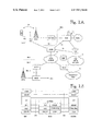
- FIG. 1A illustrates a GPRS packet radio network implemented in the GSM system.
- the basic structure of the GSM system comprises two elements: a base station system BSS and a network subsystem NSS.
- the BSS and mobile stations MS communicate over radio links.
- each cell is served by a base station BTS.
- a number of base stations are connected to a base station controller BSC, which controls the radio frequencies and channels used by the BTS.
- Base station controllers BSC are connected to a mobile services switching centre MSC.
- ETSI/GSM recommendations and The GSM System for Mobile Communications M. Mouly and M. Pautet, Palaiseau, France, 1992, ISBN:2-957190-07-7.
- the GPRS system connected to the GSM network comprises one GPRS network, which in turn comprises two serving GPRS support nodes (SGSN) and one GPRS gateway support node (GGSN).
- the different support nodes SGSN and GGSN are interconnected by an intra-operator backbone network.
- a GPRS network there may be any number of support nodes and gateway support nodes.
- the serving GPRS support node SGSN is a node which serves a mobile station MS.
- Each support node SGSN controls a packet data service within the area of one or more cells in a cellular packet radio network, and therefore each support node SGSN is connected (via a Gb interface) to a certain local element of the GSM system.
- This connection is typically established to the base station system BSS, i.e. to base station controllers BSC or to a base station BTS.
- a mobile station MS located in a cell communicates with a base station BTS over a radio interface and further with the support node SGSN to the service area of which the cell belongs through the mobile communication network.
- the mobile communication network between the support node SGSN and the mobile station MS only relays packets between these two.
- the mobile communication network provides packet-switched transmission of data packets between the mobile station MS and the serving support node SGSN.
- the mobile communication network only provides a physical connection between the mobile station MS and the support node SGSN, and thus its exact function and structure are not significant with respect to the invention.
- the SGSN is also provided with a signalling interface Gs (e.g. an SS7 signalling connection) to the visitor location register VLR of the mobile communication network and/or to the mobile services switching centre.
- the SGSN may transmit location information to the MSC/VLR and/or receive requests for paging a GPRS subscriber from the MSC/VLR.
- the SGSN When the MS attaches to the GPRS network, i.e. in a GPRS attach procedure, the SGSN creates a mobility management (MM) context containing, for example, information related to the mobility and security of the MS. In connection with a PDP activation procedure the SGSN creates a PDP (packet data protocol) context which is used for routing purposes within the GPRS network with the GGSN which the GPRS subscriber uses.
- MM mobility management
- PDP packet data protocol
- the GPRS gateway support node GGSN connects an operator's GPRS network to other operators' GPRS systems and to data networks 11-12, such as an inter-operator backbone network, IP network (Internet) or X.25 network.
- the GGSN includes GPRS subscribers' PDP addresses and routing information, i.e. SGSN addresses. Routing information is used for tunneling protocol data units PDU from data network 11 to the current switching point of the MS, i.e. to the serving SGSN.
- Functionalities of the SGSN and GGSN nodes can be integrated into one physical node.
- a home location register HLR of the GSM network contains GPRS subscriber data and routing information and it maps the subscriber's IMSI into one or more pairs of the PDP type and PDP address.
- the HLR also maps each pair of PDP type and PDP address into one or more GGSNs.
- the SGSN has a Gr interface to the HLR (a direct signalling connection or a connection via an internal backbone network 13).
- the HLR of a roaming MS may be in a different mobile communication network than the serving SGSN.
- An intra-operator backbone network 13 which interconnects the SGSN and GGSN equipment of an operator, can be implemented, for example, by means of a local network, such as an IP network. It should be noted that a GPRS network of an operator can also be implemented without the intra-operator backbone network, e.g. by providing all features in one computer.
- An inter-operator backbone network is a network via which different operators' gateway support nodes GGSN can communicate with one another.
- FIG. 1B illustrates protocol layers of the signalling level between an MS and an SGSN.
- layered protocol structures known as a transmission level and a signalling level, have been defined for transmitting user information and signalling.
- a transmission level has a layered protocol structure providing transmission of user information together with control procedures of data transmission related to it (e.g. flow control, error detection, error correction and error recovery).
- a signalling level consists of protocols which are used for controlling and supporting the functions of the transmission level, such as controlling access to the GPRS network (Attach and Detach) and controlling the routing path of the established network connection in order to support user mobility.
- the protocol layers of the transmission level are identical with those of FIG. 2 up to protocol layer SNDCP, above which there is a protocol of the GPRS backbone network (e.g. the Internet Protocol IP) between the MS and the GGSN (instead of protocol L3MM).
- the protocol layers illustrated in FIG. 1B are:
- the most interesting protocol layers are the LCC and the L3MM.
- the function of the LLC layer can be described as follows: the LLC layer functions above the RLC layer in the reference architecture and establishes a logical link between the MS and its serving SGSN.
- the most important requirements are a reliable management of the LCC frame relay and support for point-to-point and point-to-multipoint addressing.
- a service access point (SAP) of the logical link layer is a point where the LLC layer provides services for the layer 3 protocols (the SNDCP layer in FIG. 1B ).
- the link of the LLC layer is identified with a data link connection identifier (DLCI), which is transmitted in the address field of each LLC frame.
- DLCI consists of two elements: A Service Access Point Identifier (SAPI) and a Temporary Logical Link Identity TLLI. When a more general expression of a TLLI is needed, the term ‘temporary identity’ will be used.
- a logical link is established between the MS and the SGSN.
- This logical link has a route between the MS and the SGSN, indicated with the TLLI identifier.
- the TLLI is a temporary identifier, which the SGSN allocates for a certain logical link and IMSI.
- the SGSN sends the TLLI to the MS in connection with the establishment of a logical link, and it is used as an identifier in later signalling and data transmission over this logical link.
- Data transmission over a logical link is carried out as explained in the following.
- Data to be transmitted to or from an MS is processed with an SNDCP function and transmitted to the LLC layer.
- the LLC layer inserts the data in the information field of LLC frames.
- the address field of a frame includes e.g. a TLLI.
- the LLC layer relays the data to the RLC, which deletes unnecessary information and segments the data into a form compatible with the MAC.
- the MAC layer activates radio resource processes in order to obtain a radio traffic path for transmission.
- a corresponding MAC unit on the other side of the radio traffic path receives the data and relays it upwards to the LLC layer.
- the data is transmitted from the LLC layer to the SNDCP, where the user data is restored completely and relayed to the next protocol layer.
- MM states of the MS are typical of the mobility management (MM) of a GPRS subscriber: an idle state, a standby state and a ready state. Each state represents a certain functionality and information level, which has been allocated to the MS and the SGSN. Information sets related to these states, called MM contexts, are stored in the SGSN and the MS.
- the context of the SGSN contains subscriber data, such as the subscriber's IMSI, TLLI and location and routing information, etc.
- the MS In the standby and ready states the MS is attached to the GPRS network.
- a dynamic MM context has been created for the MS, and a logical link LLC (Logical Link Control) is established between the MS and the SGSN in a protocol layer.
- the ready state is the actual data transmission state in which the MS can transmit and receive user data.
- the MS switches from the standby state to the ready state either when the GPRS network pages the MS or when the MS initiates data transmission or signalling.
- the MS may remain in the ready state (for a period set with a timer) even when no user data is transmitted nor signalling performed.
- the MS also has one or more PDP contexts (Packet Data Protocol), which are stored in the serving SGSN in connection with the MM context.
- the PDP context defines different data transmission parameters, such as the PDP type (e.g. X.25 or IP), PDP address (e.g. X.121 address), quality of service QoS and NSAPI.
- the MS activates the PDU context with a specific message, Activate PDP Context Request, in which it gives information on the TLLI, PDP type, PDP address, required QoS and NSAPI.
- PDP Context Request in which it gives information on the TLLI, PDP type, PDP address, required QoS and NSAPI.
- a routing area is an area defined by an operator, comprising one or more cells. Usually, one SGSN serves several routing areas. A routing area is used for determining the location of the MS in the standby state. If the location of the MS is not known in terms of a specific cell, signalling is started with a GPRS page within one routing area RA. In other words, a paging area is normally also a routing area in a GPRS system, and a location area in a current GSM system.
- the MS performs a routing area update procedure in order to support mobility of a packet-switched logical link.
- the MS initiates the procedure when a new cell is selected, the routing area changes or an update timer of a cyclic routing area expires.
- the radio network (PLMN) is arranged to transmit a sufficient amount of system information to the MS so that it can detect when it enters a new cell or a new routing area RA and to determine when it is to carry out cyclic routing area updates.
- the MS detects that it has entered a new cell by comparing cyclically the cell identity (Cell ID) which is stored in its MM context with the cell identity which is received from the network.
- Cell ID cell identity
- the MS detects that it has entered a new routing area RA by comparing the routing area identifier stored in its MM context with the routing area identifier received from the network.
- the MS selects a new cell, it stores the cell identity and routing area in its MM context.
- the new SGSN On the basis of the old routing area information transmitted by the MS in an update message the new SGSN detects that a routing area update is in progress between two SGSN nodes, and it activates the necessary interrogation to the old SGSN in order to create new MM and PDP contexts for the MS to the new SGSN. Since the SGSN has changed, the logical link should be re-established between the MS and the new SGSN.
- FIG. 2 which is originally FIG. 17 of ETSI Recommendation GSM 03.60 (version 6.0.0), is a signalling diagram illustrating (mainly) a prior art attach procedure.
- the mobile station's former support node SGSN and mobile switching centre MSC/VLR are called “old” and the current ones are called “new”.
- the MS sends an A TTACH R EQUEST .
- Steps 2-2 to 2-5 are not necessary for understanding the invention and these steps will not be described.
- step 2-6a the new node, SGSN2, sends an U PDATE L OCATION message to the HLR, which in step 2-6b sends a C ANCEL L OCATION to the old SGSN1.
- step 2-6d the new SGSN2 receives the subscriber's data in a message I NSERT S UBSCRIBER D ATA and acknowledges in step 2-6e.
- step 2-6f the new SGSN2 receives from the HLR an acknowledgement to the location update sent in step 2-6a.
- step 2-7a the new SGSN2 sends a L OCATION U PDATING R EQUEST to the new MSC/VLR.
- steps 2-7b through 2-7g correspond to steps 2-6a through 2-6f.
- step 2-7h the new SGSN2 receives from the new MSC an acknowledgement to the location update sent in step 2-7a.
- step 2-8 the new SGSN2 reports to the MS that the A TTACH R EQUEST sent in step 2-1 has been accepted. The remaining steps are not relevant to the invention and will not be described.
- FIG. 3 which is originally FIG. 26 of ETSI Recommendation GSM 03.60 (version 6.0.0), is a signalling diagram illustrating (mainly) a prior art routing area update procedure.
- an inter-SGSN routing area update procedure the serving SGSN changes and the MS should be informed of the change so that the MS can initiate a local procedure or a network procedure for updating a logical link.
- the reference numbers refer to messages or events shown in FIG. 3 .
- the MS sends a routing area update request to the new SGSN2.
- This message includes the temporary logical link identity TLLI, the cell identity of the new cell Cell_id, the routing area identifier of the old routing area RA_id, and the routing area identifier of the new routing area RA_id. If load is to be decreased in the radio interface, the cell identity Cell_id is not added until in the base station system BSS.
- the new SGSN2 detects that the old routing area belongs to another SGSN, which will be referred to as an old node, SGSN1. As a result, the new SGSN2 requests MM and PDP contexts for the MS in question from the old SGSN1. All contexts can be requested at the same time, or the MM context and each PDP context can be requested in different messages.
- the request(s) includes at least the routing area identifier RA_id of the old routing area and the TLLI.
- the old SGSN1 sends in response an MM context, PDP contexts and possibly authorization parameter triplets. If the MS is not recognized in the old SGSN1, the old SGSN1 replies with an appropriate error message.
- the old SGSN1 stores the new SGSN2 address until the old MM context has been deleted so that data packets can be relayed from the old SGSN1 to the new SGSN2.
- the new SGSN2 sends a message “Modify PDP Context Request” including e.g. a new SGSN address to the GGSNs concerned.
- the GGSNs update their PDP context fields and send in response a message “Modify PDP Context Response”.
- the new SGSN2 informs the HLR of the change of the SGSN by sending a message “Update Location” including a new SGSN address and an IMSI.
- the HLR deletes the MM context from the old SGSN1 by sending it a message “Cancel Location” including an IMS1.
- the old SGSN1 deletes the MM and PDP contexts and acknowledges this by sending a message “Cancel Location Ack”.
- the HLR sends a message “Insert Subscriber Data” including an IMSI and GPRS subscriber data to the new SGSN2.
- the new SGSN2 acknowledges this by sending a message “Insert Subscriber Data Ack”.
- the HLR acknowledges the location update by sending a message “Update Location Ack” to the SGSN.
- the association between the SGSN and the VLR has to be updated.
- the VLR address is deduced from the RA information.
- the new SGSN transmits a message “Location Updating Request” including e.g. an SGSN address and an IMSI to the VLR.
- the VLR stores the SGSN address and acknowledges by sending a message “Location Updating Accept”.
- the new SGSN2 confirms the presence of the MS in the new routing area RA. If there are no restrictions for registration of the MS for the new RA, the SGSN creates MM and PDP contexts for the MS. A logical link will be established between the new SGSN and the MS. The new SGSN2 replies to the MS with a message “Routing Area Update Accept” including e.g. a new TLLI. This message tells the MS that the network has succeeded in carrying out the update.
- the MS acknowledges the new TLLI with a message “Routing Area Update Complete”.
- the new supporting network element may have trouble in determining the old supporting network element on the basis of the paging area identifier. There is also a risk of two supporting network elements allocating the same TLLI to two different mobile stations.
- An object of the invention is to minimise the problems and disadvantages resulting from the prior art temporary identity (TLLI/TMSI) allocation method.
- the basic idea of the invention is that the network element allocating the temporary identity encodes its own identifier, or part of it, into the temporary identity. For example, if the length of the TLLI is 32 bits, a few bits (such as 3, 4 or 5) can be used to identify the network element allocating the TLLI, whereby 8, 16 or 32 network elements, respectively, could support a single routing/paging/location area.
- the TLLI according to the invention is used e.g. by a BSC/RNC to determine the network element to which it should send the packets addressed to a certain mobile station. It is also used by any network element receiving an unknown mobile station to determine the identity of the network element currently supporting the mobile station in question.
- the invention provides a simple and effective way for a base station subsystem (BSS) serving the mobile station to keep track of which network element currently supports the mobile station in question. This is especially useful if a BSS is connected to many network elements.
- BSS base station subsystem
- FIG. 1A illustrates GPRS network architecture
- FIG. 1B illustrates protocol layers of the signalling level between an MS and an SGSN
- FIG. 2 is a signalling diagram illustrating an attach procedure
- FIG. 3 is a signalling diagram illustrating a routing area update procedure
- FIG. 4 illustrates the concept of a domain name server in connection with a packet radio system.
- the present invention can be applied to packet radio systems of various kinds.
- the invention can be used especially preferably for providing a general packet radio service GPRS in the pan-European digital mobile communication system GSM (Global System for Mobile Communication) or in corresponding mobile communication systems, such as the DCS1800 and the PCS (Personal Communication System), or in a more advanced system, such as the UMTS (Universal Mobile Telecommunications System).
- GSM Global System for Mobile Communication
- DCS1800 and the PCS Personal Communication System
- UMTS Universal Mobile Telecommunications System
- the preferred embodiments of the invention will be described by means of a GPRS packet radio network formed by the GPRS service and the GSM system without limiting the invention to this particular packet radio system.
- a radio network controller RNC may be used instead of a BSC, etc.
- the MS detects a new cell or a new routing area RA
- the MS selects a new cell locally and stores the cell identity in its MM context.
- the attach procedure shown in FIG. 2 is modified so that in step 2-8 the A TTACH A CCEPT message comprises the inventive temporary identity (e.g. TLLI) which indicates (i.e. comprises at least part of) the identifier of the SGSN that allocated the temporary identity.
- the TLLI comprises part of the identifier of SGSN2.
- the attach procedure per se is not modified, but the temporary identity sent comprises at least a part of the identity of the network element that allocated the temporary identity.
- the inventive temporary identity/TLLI can be seen in step 3-1 of FIG. 3 . Because the Routing Area Update Request indicates in the TLLI coding the identity of the SGSN node (SGSN1) which allocated the TLLI, the new SGSN2 can deduce the proper SGSN address using the old routing area identity together with the TLLI coding, typically using a database functionality.
- a cell update is performed when the MS enters a new cell within the current routing area RA and is in the READY state. If the RA has changed, a routing area update is carried out instead of the cell update.
- the cell update procedure is carried out as an implicit procedure at the LLC level, which means that normal LLC information and control frames are used for sending information on crossover to the SGSN.
- the cell identity is added to the BSSGB packets for all LLC frames in the base station system of the network.
- the SGSN registers the crossover of the MS, and any further traffic toward the MS is routed via a new cell.
- the SGSN does not change, and problems overcome by the invention will not arise.
- the SGSN may also use another suitable signalling sequence for initiating the establishment of a logical link in the LLC layer or in another protocol layer.
- the TLLI of the mobile station indicates the network element that allocated the TLLI.
- the TLLI indicates the old SGSN1.
- 3 to 5 bits are not sufficient to unambiguously indicate a large number of SGSN nodes.
- these 3 to 5 bits can be reused in a manner somewhat analogous to a frequency reuse pattern as used in the GSM system, whereby the combination of the routing area of the GPRS system and the inventive TLLI coding can unambiguously determine an SGSN node.
- step 2-2 the new SGSN2 knows the identity of the old SGSN1 even if there is a many-to-many relationship between routing areas and SGSN nodes. This is because the mobile station MS has sent, in the A TTACH R EQUEST 2-1, the old TLLI and the RAI. If the MS does not send the old TLLI, then in step 2-3 the MS should be identified.
- the TLLI comprises two identifiers, one indicating the paging area and the other one indicating the BSC/RNC.
- the temporary identity or TLLI according to the invention can be linked to a specific network element by means of a suitable database.
- a network element A receiving a TLLI can derive the corresponding network element B by using the routing area identifier associated with the TLLI, which allows it to send some signalling (such as a location update message) to network element B.
- Network element B will reply directly if it handles the mobile station itself, or it will forward the signalling to the correct network element.
- the old SGSN can forward the request to the valid SGSN.
- the valid address being retrieved from a database the request is sent to an entity which is able to find the valid address (using the old RAI and the TLLI) and to forward the request to the old SGSN handling the MS.
- the response could be sent by SGSN3 to SGSN1 directly or via another entity (SGSN2).
- SGSN2 a combination of 1 and 2 can be used, in which case the NEI is part of the TLLI but the SGSN (e.g. by a different manufacturer) is not able to use it.
- the old SGSN address stored in the domain name server can be replaced by a node address which uses the NEI and the RAI (or the LAI).
- FIG. 4 illustrates the concept of a domain name server DNS in connection with a packet radio system, such as the GPRS.
- an MS sends a Routing Area Update Request to SGSN2 (“the new SGSN”).
- This request comprises the MS's old Routing Area Index RAI and the TLLI according to the invention.
- SGSN2 sends them to a domain name server DNS. Together they form an unambiguous combination and in step 4-3 the DNS is able to return the address of SGSN1 (“old SGSN”).
- the new SGSN2 is able to retrieve the SGSN context from the old SGSN1.
- a mobile station can be paged with different identities if it is registered in more than one network element. However, it would be simpler if the mobile station listened to only one identity on the paging channel.
- an extended temporary identity or TLLI is used.
- the extended temporary identity or TLLI comprises up to three identifiers as follows:
- the first octet a network element identifier unique to the paging area
- the second octet a network element identifier unique to the RNC/BSC;
- the paging identity can be a pseudorandom number co-ordinated by the network. It can be allocated by the BSS/RNC or by a separate master network element. For example, for each routing area RA a single SGSN would allocate all the paging identities valid in that RA. The other SGSN nodes should request the paging identity from this master SGSN. It should be unique to each mobile station so that in order to page a mobile station registered in the paging area in question, it is sufficient to use this paging identity. When a mobile station which is not yet registered in the paging area is paged, the use of the extended TLLI reduces the risk of collision. For uplink transmission and mobility management signalling, the mobile station should use the extended identity.
- the NEI that is unique to the paging area should identify the SGSN uniquely. In other words, 3 to 5 bits can identify 2 3 to 2 5 SGSN nodes.
- the first octet of the extended temporary identity comprises the full network element identifier unique to the paging area.
- the temporary identity is used for downlink transfer and paging.
- Another way of expressing this is that the TLLI is still the paging identity but the NEI is associated with it.
- the inventive NEI can be used as follows.
- the SGSN receiving an MT packet knows the identity of the MS and the cell it is located in. Therefore, downlink packets can be routed to the MS without the inventive NEI.
- Uplink packets are sent by an MS to a BSC, which may be connected to many SGSN nodes. Thus the MS must send the NEI in every packet to enable the BSC to route the packet to the correct SGSN.
- the BSC maintains a context for the MS, in which the relevant SGSN is indicated.
- the BSC serving the MS can change too. Therefore, the MS should insert the NEI in every packet after a cell/routing area change.
- the first packet sent after a cell/routing area change could be a signalling message, such as a routing area update, or it may be a normal user data packet which can be used in a GPRS system for indicating an implicit cell update.
- the new SGSN derives the address of the old SGSN on the basis of the old RAI.
- the MS should include the NEI in an RA Update message so that the new SGSN can find the old SGSN on the basis of the old RAI and the NEI.
- an RNC will maintain a context for each MS.
- the paging area border might be different from an RNC area border.
- two (or more) RNC nodes RNC1 and RNC2, not shown) could serve a single paging area but the MS has a context in RNC1 although it is located in the area of RNC2 where it is to be paged.
- the mobile station should include the RNC NEI in the paging response.
- RNC2 knows that the MS has a context in RNC1 and RNC2 should retrieve the context from RNC1.
- this new paging area might be handled by a new RNC.
- the MS should include the RNC NEI in the paging area update message.
- Standardization of the GPRS system is not yet final.
- the present state of the GPRS system is described in the accepted recommendations GSM 03.60 version 6.1.0 and the LLC is described in GSM 04.64, version 6.1.0 of the European Telecommunications Standards Institute (ETSI), which are incorporated herein by reference.
- ETSI European Telecommunications Standards Institute
Abstract
Description
-
- The Layer 3 Mobility Management (L3MM): this protocol supports the functionality of mobility management, e.g. GPRS Attach, GPRS Detach, security, routing area update, location area update, activation of a PDP context, and deactivation of a PDP context.
- The Subnetwork Dependent Convergence Protocol (SNDCP) supports transmission of protocol data units (N-PDU) of a network layer between an MS and an SGSN. The SNDCP layer, for example, manages ciphering and compression of N-PDUs.
- The Logical Link Control (LLC): this layer provides a very reliable logical link. The LLC is independent of the radio interface protocols mentioned below.
- The LLC Relay: this function relays LLC protocol data units (PDU) between an MS-BSS interface (Urn) and a BSS-SGSN interface (Gb).
- The Base Station Subsystem GPRS Protocol (BSSGP): this layer transmits routing information and information related to QoS between a BSS and an SGSS.
- The Frame Relay, which is used over the Gb interface. A semipermanent connection for which several subscribers' LLC PDUs are multiplexed is established between the SGSN and the BSS.
- The Radio Link Control (RLC): this layer provides a reliable link independent of radio solutions.
- The Medium Access Control (MAC): this one controls access signalling (request and grant) related to a radio channel and mapping of LLC frames onto a physical GSM channel.
Claims (19)
Applications Claiming Priority (3)
| Application Number | Priority Date | Filing Date | Title |
|---|---|---|---|
| FI982166A FI106288B (en) | 1998-10-06 | 1998-10-06 | Identifying a mobile station in a packet radio network |
| FI982166 | 1998-10-06 | ||
| PCT/FI1999/000825 WO2000021319A1 (en) | 1998-10-06 | 1999-10-05 | Identifying a mobile station in a packet radio network |
Publications (1)
| Publication Number | Publication Date |
|---|---|
| US7957736B1 true US7957736B1 (en) | 2011-06-07 |
Family
ID=8552652
Family Applications (1)
| Application Number | Title | Priority Date | Filing Date |
|---|---|---|---|
| US09/806,939 Expired - Fee Related US7957736B1 (en) | 1998-10-06 | 1999-10-05 | Identifying a mobile station in a packet radio network |
Country Status (11)
| Country | Link |
|---|---|
| US (1) | US7957736B1 (en) |
| EP (1) | EP1119997B1 (en) |
| JP (2) | JP4226786B2 (en) |
| CN (1) | CN1123272C (en) |
| AT (1) | ATE290759T1 (en) |
| AU (1) | AU6092099A (en) |
| DE (1) | DE69924130C5 (en) |
| ES (1) | ES2237154T3 (en) |
| FI (1) | FI106288B (en) |
| PT (1) | PT1119997E (en) |
| WO (1) | WO2000021319A1 (en) |
Cited By (4)
| Publication number | Priority date | Publication date | Assignee | Title |
|---|---|---|---|---|
| US20070117575A1 (en) * | 2005-11-07 | 2007-05-24 | Alcatel | Method for connection re-establishment in a mobile communciation system |
| US20130052986A1 (en) * | 2010-05-10 | 2013-02-28 | Zte Corporation | Method and apparatus for inter-system reselection frequency statistics |
| US20130121241A1 (en) * | 2011-11-16 | 2013-05-16 | Renesas Mobile Corporation | Indication of Selected Core Network in a Network Sharing Environment |
| US9155058B2 (en) | 2005-07-14 | 2015-10-06 | Interdigital Technology Corporation | Wireless communication system and method of implementing an evolved system attachment procedure |
Families Citing this family (27)
| Publication number | Priority date | Publication date | Assignee | Title |
|---|---|---|---|---|
| US6829482B2 (en) * | 2000-05-16 | 2004-12-07 | Telefonaktiebolaget Lm Ericsson (Publ) | Switching from dedicated to common channels when radio resources are controlled by drift radio network |
| AU2000245676A1 (en) * | 2000-05-22 | 2001-12-03 | Nokia Corporation | System and method for providing a connection in a communication network |
| GB0015715D0 (en) * | 2000-06-27 | 2000-08-16 | Nokia Networks Oy | Maintaining association in a communications network |
| AU2000258238A1 (en) | 2000-07-03 | 2002-01-14 | Nokia Corporation | Communication system and method |
| DE10046343B4 (en) * | 2000-09-19 | 2005-08-18 | Siemens Ag | Method for registering a terminal in a packet data network |
| GB2367454B (en) * | 2000-09-27 | 2004-05-19 | Motorola Inc | Cellular communications system and method for signalling therein |
| US6564059B1 (en) * | 2000-10-11 | 2003-05-13 | Lucent Technologies Inc. | Modification of link identifier to include routing label that allows base station message routing to serving processor |
| AU2000277874A1 (en) | 2000-10-13 | 2002-04-22 | Nokia Corporation | Method and system for attaching a mobile equipment to a wireless communication network |
| SE518479C2 (en) * | 2000-10-13 | 2002-10-15 | Ericsson Telefon Ab L M | Communication systems that support wireless communication of packet data and method and device related thereto |
| WO2002045451A1 (en) * | 2000-12-01 | 2002-06-06 | Nokia Corporation | A method of performing an area update for a terminal equipment in a communication network |
| US6708031B2 (en) * | 2000-12-05 | 2004-03-16 | Nokia Corporation | Session or handoff methods in wireless networks |
| DE10117269B4 (en) | 2001-03-30 | 2005-12-08 | Siemens Ag | Method for assigning a mobile communication terminal to a core network node |
| NO20013194D0 (en) * | 2001-06-25 | 2001-06-25 | Ericsson Telefon Ab L M | Assignment of temporary identities in mobile networks |
| GB0403829D0 (en) * | 2004-02-20 | 2004-03-24 | Nokia Corp | Handover for packet switched data |
| JP4301989B2 (en) * | 2004-03-31 | 2009-07-22 | 株式会社エヌ・ティ・ティ・ドコモ | Mobile communication method and radio control apparatus |
| CN100420331C (en) * | 2004-09-04 | 2008-09-17 | 华为技术有限公司 | Method for sharing wireless accessing net by multi operators |
| US7167459B2 (en) * | 2004-12-30 | 2007-01-23 | Motorola, Inc. | Inter-network handover in a packet radio system |
| US20060234709A1 (en) * | 2005-03-30 | 2006-10-19 | Nokia Corporation | System, devices, methods and programs for reducing service interruption during routing area change |
| SG136003A1 (en) * | 2006-03-24 | 2007-10-29 | Nokia Corp | Improved information transfer during handover |
| US20070280177A1 (en) * | 2006-05-31 | 2007-12-06 | Nokia Corporation | Managing user profile information in a mobile telecommunications network |
| EP1973276A1 (en) * | 2007-03-19 | 2008-09-24 | Nokia Siemens Networks Gmbh & Co. Kg | Method for providing an identity to a user equipment and apparatus thereof |
| EP1991014B1 (en) | 2007-05-11 | 2012-11-28 | Nokia Siemens Networks S.p.A. | Method to attach a mobile station to a second generation packet network shared between different operators |
| US20080293412A1 (en) * | 2007-05-25 | 2008-11-27 | Nokia Corporation | Location update with multipoint functionality |
| US8902805B2 (en) * | 2008-10-24 | 2014-12-02 | Qualcomm Incorporated | Cell relay packet routing |
| JP4859967B2 (en) * | 2009-08-25 | 2012-01-25 | 株式会社エヌ・ティ・ティ・ドコモ | Circuit-switched call processing node, mobile communication system, and mobile communication method |
| WO2012050505A1 (en) * | 2010-10-12 | 2012-04-19 | Telefonaktiebolaget Lm Ericsson (Publ) | Method and network node |
| CN109644429A (en) * | 2016-09-30 | 2019-04-16 | 华为技术有限公司 | A kind of paging zone configuration method and device |
Citations (10)
| Publication number | Priority date | Publication date | Assignee | Title |
|---|---|---|---|---|
| US5361396A (en) * | 1990-09-14 | 1994-11-01 | Nippon Telegraph And Telephone Corp. | Location registration system in mobile communication |
| WO1997033403A1 (en) | 1996-03-04 | 1997-09-12 | Nokia Telecommunications Oy | Improving security of packet-mode transmission in a mobile communication system |
| WO1997048246A1 (en) | 1996-06-14 | 1997-12-18 | Telefonaktiebolaget Lm Ericsson (Publ) | Method and apparatus for addressing a wireless communication station with a dynamically-assigned address |
| EP0859531A2 (en) | 1997-01-15 | 1998-08-19 | Telefonaktiebolaget Lm Ericsson | Method for providing a unique temporary indentification of a mobile station |
| WO1999016036A1 (en) | 1997-09-24 | 1999-04-01 | Eldridge Martin E | Position-responsive, hierarchically-selectable information presentation system and control program |
| US5920814A (en) * | 1997-04-30 | 1999-07-06 | Telefonaktiebolaget | System and method of managing temporary mobile station identity (TMSI) parameters in a radio telecommunications network |
| US6081723A (en) * | 1996-03-26 | 2000-06-27 | Siemens Aktiengesellschaft | Method and arrangement for the location area management in a cellular mobile radiotelephone network |
| US6356761B1 (en) * | 1997-09-04 | 2002-03-12 | Telefonaktiebolaget Lm Ericsson (Publ) | Method and arrangement for finding information |
| US6381454B1 (en) * | 1995-10-10 | 2002-04-30 | Qualcomm Incorporated | Method and system for over-the-air (OTA) service programming |
| US20020086685A1 (en) * | 1998-05-05 | 2002-07-04 | Telefonaktiebolaget Lm Ericsson | Multicell area paging for cellular telecommunications system |
-
1998
- 1998-10-06 FI FI982166A patent/FI106288B/en not_active IP Right Cessation
-
1999
- 1999-10-05 WO PCT/FI1999/000825 patent/WO2000021319A1/en active IP Right Grant
- 1999-10-05 AU AU60920/99A patent/AU6092099A/en not_active Abandoned
- 1999-10-05 JP JP2000575325A patent/JP4226786B2/en not_active Expired - Lifetime
- 1999-10-05 EP EP99947502A patent/EP1119997B1/en not_active Expired - Lifetime
- 1999-10-05 US US09/806,939 patent/US7957736B1/en not_active Expired - Fee Related
- 1999-10-05 PT PT99947502T patent/PT1119997E/en unknown
- 1999-10-05 AT AT99947502T patent/ATE290759T1/en active
- 1999-10-05 CN CN99811826A patent/CN1123272C/en not_active Expired - Lifetime
- 1999-10-05 ES ES99947502T patent/ES2237154T3/en not_active Expired - Lifetime
- 1999-10-05 DE DE69924130.8T patent/DE69924130C5/en not_active Expired - Lifetime
-
2005
- 2005-07-07 JP JP2005199251A patent/JP2006005950A/en active Pending
Patent Citations (11)
| Publication number | Priority date | Publication date | Assignee | Title |
|---|---|---|---|---|
| US5361396A (en) * | 1990-09-14 | 1994-11-01 | Nippon Telegraph And Telephone Corp. | Location registration system in mobile communication |
| US6381454B1 (en) * | 1995-10-10 | 2002-04-30 | Qualcomm Incorporated | Method and system for over-the-air (OTA) service programming |
| WO1997033403A1 (en) | 1996-03-04 | 1997-09-12 | Nokia Telecommunications Oy | Improving security of packet-mode transmission in a mobile communication system |
| US6081723A (en) * | 1996-03-26 | 2000-06-27 | Siemens Aktiengesellschaft | Method and arrangement for the location area management in a cellular mobile radiotelephone network |
| WO1997048246A1 (en) | 1996-06-14 | 1997-12-18 | Telefonaktiebolaget Lm Ericsson (Publ) | Method and apparatus for addressing a wireless communication station with a dynamically-assigned address |
| EP0859531A2 (en) | 1997-01-15 | 1998-08-19 | Telefonaktiebolaget Lm Ericsson | Method for providing a unique temporary indentification of a mobile station |
| US6208628B1 (en) * | 1997-01-15 | 2001-03-27 | Telefonaktiebolaget Lm Ericsson (Publ) | Method for providing a unique temporary identification of a mobile station |
| US5920814A (en) * | 1997-04-30 | 1999-07-06 | Telefonaktiebolaget | System and method of managing temporary mobile station identity (TMSI) parameters in a radio telecommunications network |
| US6356761B1 (en) * | 1997-09-04 | 2002-03-12 | Telefonaktiebolaget Lm Ericsson (Publ) | Method and arrangement for finding information |
| WO1999016036A1 (en) | 1997-09-24 | 1999-04-01 | Eldridge Martin E | Position-responsive, hierarchically-selectable information presentation system and control program |
| US20020086685A1 (en) * | 1998-05-05 | 2002-07-04 | Telefonaktiebolaget Lm Ericsson | Multicell area paging for cellular telecommunications system |
Cited By (6)
| Publication number | Priority date | Publication date | Assignee | Title |
|---|---|---|---|---|
| US9155058B2 (en) | 2005-07-14 | 2015-10-06 | Interdigital Technology Corporation | Wireless communication system and method of implementing an evolved system attachment procedure |
| US20070117575A1 (en) * | 2005-11-07 | 2007-05-24 | Alcatel | Method for connection re-establishment in a mobile communciation system |
| US8515462B2 (en) * | 2005-11-07 | 2013-08-20 | Alcatel Lucent | Method for connection re-establishment in a mobile communication system |
| US20130052986A1 (en) * | 2010-05-10 | 2013-02-28 | Zte Corporation | Method and apparatus for inter-system reselection frequency statistics |
| US8831558B2 (en) * | 2010-05-10 | 2014-09-09 | Zte Corporation | Method and apparatus for inter-system reselection frequency statistics |
| US20130121241A1 (en) * | 2011-11-16 | 2013-05-16 | Renesas Mobile Corporation | Indication of Selected Core Network in a Network Sharing Environment |
Also Published As
| Publication number | Publication date |
|---|---|
| CN1123272C (en) | 2003-10-01 |
| ATE290759T1 (en) | 2005-03-15 |
| AU6092099A (en) | 2000-04-26 |
| FI982166A0 (en) | 1998-10-06 |
| PT1119997E (en) | 2005-06-30 |
| CN1322453A (en) | 2001-11-14 |
| JP2002527966A (en) | 2002-08-27 |
| WO2000021319A1 (en) | 2000-04-13 |
| FI106288B (en) | 2000-12-29 |
| JP4226786B2 (en) | 2009-02-18 |
| DE69924130T2 (en) | 2006-04-13 |
| ES2237154T3 (en) | 2005-07-16 |
| EP1119997B1 (en) | 2005-03-09 |
| DE69924130D1 (en) | 2005-04-14 |
| EP1119997A1 (en) | 2001-08-01 |
| JP2006005950A (en) | 2006-01-05 |
| DE69924130C5 (en) | 2019-06-27 |
Similar Documents
| Publication | Publication Date | Title |
|---|---|---|
| US7957736B1 (en) | Identifying a mobile station in a packet radio network | |
| US6512756B1 (en) | Routing area updating in packet radio network | |
| US6661782B1 (en) | Routing area updating in packet radio network | |
| US6233458B1 (en) | Re-routing procedure | |
| US7471957B2 (en) | Paging method and system for a radio access network | |
| JP4523172B2 (en) | Method and apparatus for transmitting information between mobile terminal and entity in radio access network | |
| US7792079B2 (en) | Communication system | |
| EP1902550B1 (en) | Wireless communication system and method of implementing an evolved system attachment procedure | |
| EP2934050B1 (en) | Apparatus and method for providing a connection | |
| JP4448036B2 (en) | Mobility management method for user equipment and communication system therefor | |
| CN101291532B (en) | Method, system and core network node for implementing load migration in pool zone | |
| US7069022B2 (en) | Method of performing an area update for a terminal equipment in a communication network | |
| EP1552717B1 (en) | Method and network node for managing interfaces in a distributed radio access network | |
| US20080220783A1 (en) | Method for Managing Communications and Related Core Network Node | |
| KR101346458B1 (en) | Wireless communication system and method of implementing an evolved system attachment procedure | |
| US20060056395A1 (en) | Handover for packet switched data | |
| EP1329121B1 (en) | Method and means for providing enhanced subscriber identity confidentiality during roming in a cellular radio communication system | |
| US6804533B1 (en) | Relocation of communication services | |
| GB2369002A (en) | Mobility management in a UMTS network | |
| KR200428029Y1 (en) | Wireless communication system of implementing an evolved system attachment procedure |
Legal Events
| Date | Code | Title | Description |
|---|---|---|---|
| AS | Assignment |
Owner name: NOKIA NETWORKS OY, FINLAND Free format text: ASSIGNMENT OF ASSIGNORS INTEREST;ASSIGNOR:HAUMONT, SERGE;REEL/FRAME:011816/0842 Effective date: 20010327 |
|
| AS | Assignment |
Owner name: NOKIA CORPORATION, FINLAND Free format text: CHANGE OF NAME;ASSIGNOR:NOKIA NETWORKS OY;REEL/FRAME:020568/0660 Effective date: 20011020 |
|
| AS | Assignment |
Owner name: NOKIA CORPORATION, FINLAND Free format text: MERGER;ASSIGNOR:NOKIA NETWORKS OY;REEL/FRAME:023915/0094 Effective date: 20031016 |
|
| FEPP | Fee payment procedure |
Free format text: PAYOR NUMBER ASSIGNED (ORIGINAL EVENT CODE: ASPN); ENTITY STATUS OF PATENT OWNER: LARGE ENTITY Free format text: PAYER NUMBER DE-ASSIGNED (ORIGINAL EVENT CODE: RMPN); ENTITY STATUS OF PATENT OWNER: LARGE ENTITY |
|
| STCF | Information on status: patent grant |
Free format text: PATENTED CASE |
|
| AS | Assignment |
Owner name: 2011 INTELLECTUAL PROPERTY ASSET TRUST, DELAWARE Free format text: CHANGE OF NAME;ASSIGNOR:NOKIA 2011 PATENT TRUST;REEL/FRAME:027121/0353 Effective date: 20110901 Owner name: NOKIA 2011 PATENT TRUST, DELAWARE Free format text: ASSIGNMENT OF ASSIGNORS INTEREST;ASSIGNOR:NOKIA CORPORATION;REEL/FRAME:027120/0608 Effective date: 20110531 |
|
| AS | Assignment |
Owner name: SISVEL INTERNATIONAL S.A., LUXEMBOURG Free format text: ASSIGNMENT OF ASSIGNORS INTEREST;ASSIGNOR:2011 INTELLECTUAL PROPERTY ASSET TRUST;REEL/FRAME:028377/0643 Effective date: 20120410 |
|
| FPAY | Fee payment |
Year of fee payment: 4 |
|
| MAFP | Maintenance fee payment |
Free format text: PAYMENT OF MAINTENANCE FEE, 8TH YEAR, LARGE ENTITY (ORIGINAL EVENT CODE: M1552); ENTITY STATUS OF PATENT OWNER: LARGE ENTITY Year of fee payment: 8 |
|
| FEPP | Fee payment procedure |
Free format text: MAINTENANCE FEE REMINDER MAILED (ORIGINAL EVENT CODE: REM.); ENTITY STATUS OF PATENT OWNER: LARGE ENTITY |
|
| LAPS | Lapse for failure to pay maintenance fees |
Free format text: PATENT EXPIRED FOR FAILURE TO PAY MAINTENANCE FEES (ORIGINAL EVENT CODE: EXP.); ENTITY STATUS OF PATENT OWNER: LARGE ENTITY |
|
| STCH | Information on status: patent discontinuation |
Free format text: PATENT EXPIRED DUE TO NONPAYMENT OF MAINTENANCE FEES UNDER 37 CFR 1.362 |
|
| FP | Lapsed due to failure to pay maintenance fee |
Effective date: 20230607 |