US7956732B2 - Vehicle hazard flasher control system - Google Patents
Vehicle hazard flasher control system Download PDFInfo
- Publication number
- US7956732B2 US7956732B2 US11/872,250 US87225007A US7956732B2 US 7956732 B2 US7956732 B2 US 7956732B2 US 87225007 A US87225007 A US 87225007A US 7956732 B2 US7956732 B2 US 7956732B2
- Authority
- US
- United States
- Prior art keywords
- hazard warning
- hazard
- warning light
- lights
- controller
- Prior art date
- Legal status (The legal status is an assumption and is not a legal conclusion. Google has not performed a legal analysis and makes no representation as to the accuracy of the status listed.)
- Expired - Fee Related, expires
Links
Images


Classifications
-
- B—PERFORMING OPERATIONS; TRANSPORTING
- B60—VEHICLES IN GENERAL
- B60Q—ARRANGEMENT OF SIGNALLING OR LIGHTING DEVICES, THE MOUNTING OR SUPPORTING THEREOF OR CIRCUITS THEREFOR, FOR VEHICLES IN GENERAL
- B60Q1/00—Arrangement of optical signalling or lighting devices, the mounting or supporting thereof or circuits therefor
- B60Q1/26—Arrangement of optical signalling or lighting devices, the mounting or supporting thereof or circuits therefor the devices being primarily intended to indicate the vehicle, or parts thereof, or to give signals, to other traffic
- B60Q1/46—Arrangement of optical signalling or lighting devices, the mounting or supporting thereof or circuits therefor the devices being primarily intended to indicate the vehicle, or parts thereof, or to give signals, to other traffic for giving flashing caution signals during drive, other than signalling change of direction, e.g. flashing the headlights or hazard lights
Definitions
- the present invention relates generally to motor vehicles and more particularly to a system for cycling vehicle lamps on and off during flasher operation to minimize current draw or to extend component service life.
- the hazard flashing function of vehicle tail and parking lamps is done to mark a highway hazard to other drivers when a vehicle, or its operator, is disabled. Often these vehicles may sit for hours or days with the four-way flashers on. Over time, with the vehicle engine off, the current draw on the battery from the hazard flashers reduces the battery current to the point that the four-way flashers fail. Under these conditions passing motorists may not see the hazard, especially at night.
- a vehicle hazard flasher function having an optimized duty cycle and an optimized operational frequency, consistent with legal requirements for flasher rate and with a vehicle's situation. Where a vehicle battery can no longer sustain the legally mandated flasher rate an optional operational mode for flasher operation at a reduced frequency is provided.
- the electronic control unit provides activation signals for switching the exterior marker lights on and off.
- Each exterior marker light is individually switched.
- a hazard flasher operation of a set of the exterior marker lights is provided in which the exterior marker lights appear to an observer to flash on and off concurrently with a frequency in a range around 1 Hz.
- the hazard flasher function is characterized by a duty cycle, which is the duration of the period an individual exterior marker light is on within a cycle and the operating frequency.
- the duty cycle and frequency of the hazard flasher function are adjusted in the present invention in response to vehicle condition in order to protect component service life and to minimize the peak current draw on the battery.
- Activation signals for the exterior marker lights are staggered so that initial current surges associated with the bulbs being turned on are not concurrent. This can be done by delaying the activation of successive bulbs slightly, so long as the delay is not apparent to an outside observer.
- Current surges can be reduced by varying the duty cycle, or the flasher function frequency, to avoid excessive cool down of the bulbs during an on/off cycle. This extends bulb service life by reducing mechanical stress on the bulb filaments.
- the system can be made responsive to whether the engine is running, and supplying electricity, or off, in determining whether to operate the flashers to maximize component service life or to promote longest possible operation of the flashers where operation must be sustained from battery power alone. Under circumstances where the engine is off and battery charge has declined to the point where it cannot sustain operation of the flasher function at legally mandated levels, the system can be programmed to reduce the hazard function frequency to allow respite to the battery and thereby allow the battery to recover to supply enough current to visibly illuminate the exterior marker lights.
- FIG. 1 is a perspective view of a school bus equipped with lighting systems with which the present invention is advantageously employed.
- FIG. 2 is a rear view of the school bus of FIG. 1 .
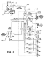
- FIG. 3 is a mixed circuit schematic and block diagram of a vehicle lighting and lighting control system.
- FIG. 4 is a flow chart illustrating operation of the invention.
- FIG. 5 is a timing diagram illustrating operation of vehicle lights in implementing the invention.
- FIG. 1 a vehicle 10 is shown.
- An assortment of exterior marker lights are mounted to the exterior of vehicle 10 , including, but not limited to, left front signal 12 , right front turn signal 14 and front pupil warning lights 16 .
- an instrument panel 15 is positioned at a driver's station 17 in the interior of vehicle 10 .
- Manual activation of a hazard flasher function using a set of the exterior marker lights is typically done from the driver station 17 using a push button switch on the instrument panel 15 .
- Additional exterior marker lights are visible in the figure including sign pupil warning lights 19 , rear pupil warning lights 18 and left and right rear turn signal lights 20 and rear brake lights 22 .
- FIG. 3 illustrates an electrical control system for a vehicle which provides lighting system control primarily through one element of that system, an electrical system controller (ESC) 30 with its associated input and output connections.
- ESC 30 is a high level controller used in a vehicle controller area network, only a stump representation of which is provided, but which includes a data link 60 and other controllers which communicate with ESC 30 over the data link such as an engine controller 40 .
- ESC 30 provides direct control over most vehicle exterior lamps including, by group: the low beam headlight filaments 61 ; the high beam headlight filaments 48 ; the parking marker lights 37 ; ID lights 38 ; the pupil warning lights (not shown); the left front turn signals 12 ; the right front turn signals 14 ; the right rear turn signals 20 ; and the left rear turn signals 22 ; etc.
- ESC 30 receives an ignition input signal 142 either directly or over the controller area network bus 60 from a gauge controller (not shown). Additional outputs may be controlled directly from the ESC 30 , such as a horn coil 36 .
- the horn coil 36 , and the park marker lights 37 , ID lights 38 , low beam filaments 61 , high beam filaments 48 and the turn signal lights 12 , 14 , 20 , 22 are all powered by switching field effect transistors 51 - 58 , which are incorporated in the ESC 30 , and which provide control over each element individually. It will be understood that in some applications these switching functions may be implemented by relays which are not incorporated in the ESC 30 , or a controller providing equivalent control over the vehicle exterior lights.
- the hazard flasher function is effected by appropriate programming which operates in part responsive to input signals received by ESC 30 over datalink 60 through a controller area network interface 143 , or directly from input switches connected to the ESC, including a set of pupil warning light control switches 222 (an example of a multiplexed analog input where ZVR stands for Zero Volt Reference) and a hazard flasher request signal 140 .
- ESC 30 may of course be connected to additional, or different, sources of inputs.
- the hazard flasher switch signal may come to the ESC 30 over the data link 60 from another controller, or over another type of data bus.
- the hazard flasher function generally uses the set of turn signal lights 12 , 14 , 20 , 22 from among the exterior marker lights.
- ESC 30 generates discrete activation signals for each of FETs 55 , 56 , 57 and 58 , although for the flasher hazard function they have synchronized to turn the turn signal lights 12 , 14 , 20 , 22 on and off in a synchronized fashion. This is seen by an observer as the front and rear turn signal lights periodically turning on and off in unison.
- an engine controller 40 which reports voltage for battery 45 , or possibly a more sophisticated estimate of charge state, and the operating status of an engine/generator combination 47 .
- Engine status may be taken as a proxy for Ignition (IGN) switch status, which is shown as applied to the engine controller, but which may be applied to another controller or even directly to ESC 30 .
- the engine controller 40 communicates with ESC 30 over a CAN data link (bus 60 ) which conforms to the SAE J1939 standard.
- bus 60 CAN data link
- FIG. 4 is a high level flow chart which illustrates execution of routine 400 implementing the invention.
- the process is entered at step 401 with activation of the hazard flasher function, typically upon closure of a hazard button by a driver.
- step 402 it is determined if the engine is operating and thus that the vehicle is generating electricity to sustain hazard flasher operation of the set of turn signal lights 12 , 14 , 20 , 22 . If the engine is on, the ON branch is followed from decision step 402 to operation step 404 which is captioned “Normal Operation”. Normal operation means that the bulbs are operated to maximize expected service life since the battery 45 is not supporting hazard flasher operation.
- the bulbs are turned off only long enough to give an observer a clear impression that the lights are flashing thereby minimizing cooling and reducing stress on the bulb filaments associated with the sudden heating occurring when they are turned on.
- the bulbs could be supplied a reduced or trickle current during the “OFF” duty cycle to prevent cool down of the bulbs with the residual current set to produce an impression that the bulb has been extinguished even though in fact it has not.
- the flasher frequency may be set in the middle of the legally permissible range. Alternatively, it is possible that the flasher operation could be reduced to the lowest allowed frequency of operation to reduce the frequency of cycling the bulbs on and off.
- Engine and hazard button status are periodically rechecked, as represented by provision of a delay step 406 and a decision step 408 following the normal operation step 404 . If the hazard function has been cancelled the OFF branch from step 408 exits the routine. If not, the ON branch is followed back to step 402 where it is determined again if the engine is running.
- Decision step 402 also provides an OFF branch provided for occasions when the hazard flasher operation of the turn signal lights 12 , 14 , 20 , 22 has been invoked, but the vehicle engine is not on.
- the OFF branch leads to an operation box captioned “Optimize Bulb Flash Rate and Duty Cycle” 410 .
- “optimization” requires selection of criteria to optimize against. With the engine off it is expected that the leading criterion is to conserve battery power, which suggests reducing the flasher frequency to the lowest rate permitted by law and shortening the on duty cycle of the bulbs to the shortest period which will illuminate the bulbs to their design intensity.
- the present invention contemplates the use of incandescent bulbs for the turn signal lights 12 , 14 , 20 , 22 , though the invention is not without application to light emitting diode (LED) systems.
- Highly efficient LEDs may be used as light fixtures in turn signal applications and it is possible that differing duty cycles and frequencies may be suitable for vehicles so equipped to minimize power usage or to meet other criteria. It is anticipated that LEDs will have expected service lives which outlast the expected service lives of the vehicles in which they are installed, with the result that operating the LEDs to maximize service life may serve little purpose.
- Incandescent bulbs exhibit a surge in current demand when initially turned on. This surge is temperature dependent, and is greater the cooler the bulb is. Thus, while it may seem reasonable to reduce operating frequency and the on duty cycle to minimize bulb current demand during four-way flasher operation, it may be beneficial, with some bulbs, and under certain weather conditions, to increase flasher frequency, or shorten the OFF period to prevent the bulbs from cooling.
- ESC 30 may, as part of its optimization programming monitor the decay of battery charge, and randomly vary the flasher rate (frequency) and the ON duty cycle to see if the introduced random variations have the benefit of slowing the rate of decay of battery charge.
- step 412 provides for staggering the activation signals of the turn signal lights 12 , 14 , 20 , 22 .
- the duty cycles of the turn signal lights 12 , 14 , 20 and 22 are staggered, resulting in the lights being turned on successively.
- the brief delay so introduced allows the initial current surge to decay as much as possible before the delay becomes noticeable to an outside observer.
- Step 414 following step 412 introduces a determination as to whether the battery state of charge has become critical, here defined as a state of charge which is unable to sustain the legally required flasher frequency and intensity. If this has occurred, the YES branch follows step 414 to step 416 .
- the operational frequency is reduced to whatever rate is needed to allow the battery to recover to the extent it can recover to support periodic illumination of the bulbs at a useful intensity. It is also possible that with a further decline in the battery state of charge, duty cycles for front turn signals could be terminated as part of hazard flasher operation with illumination limited to the rear turn signal lights 20 , 22 if insufficient current can be sourced from battery 45 to sufficiently illuminate four-way hazard flashing. From step 416 , or along the NO branch from step 414 , execution is returned to step 406 and following as described above. For an electric vehicle steps 402 and 404 may be disregarded, since battery charge conservation will be the primary consideration.
- Each cycle comprises two time periods, e.g., T 2 to T 3 and T 3 to T 4 .
- the lights are on for a portion of one time period and off in the other (excluding the possibility of a residual current).
- the periods, though shown to be equal in duration need not be of equal duration.
- the OFF period may be shortened relative to the period including ON pulses to reduce temperature decay of the filaments of the bulbs.
- the total duration of the duty cycles may be adjusted as required to either minimize total current drawn or to maintain an even filament temperature to promote long service life.
- the OFF period is simply a period when all bulbs are concurrently extinguished (or operated at a much lower intensity) which is of sufficient duration to be noticed by an observer.
- the “ON” period is the portion of the cycle which contains all of the staggered duty cycles for one flasher cycle.
- the duty cycle (DC) for each bulb comprises a portion of the ON period of a cycle.
- Lead acid battery charge is drained more quickly by imposing high peak loads on the battery even where the total cumulative current drawn is fixed.
- the duty cycles are staggered, with the bulbs being turned on successively to reduce peak load on the battery when the engine is not on and cannot support battery charging.
- the degree to which duty cycles may be staggered is limited only by the need to avoid the staggering becoming visible to an observer.
Landscapes
- Engineering & Computer Science (AREA)
- Mechanical Engineering (AREA)
- Lighting Device Outwards From Vehicle And Optical Signal (AREA)
Abstract
Description
Claims (9)
Priority Applications (1)
| Application Number | Priority Date | Filing Date | Title |
|---|---|---|---|
| US11/872,250 US7956732B2 (en) | 2007-10-15 | 2007-10-15 | Vehicle hazard flasher control system |
Applications Claiming Priority (1)
| Application Number | Priority Date | Filing Date | Title |
|---|---|---|---|
| US11/872,250 US7956732B2 (en) | 2007-10-15 | 2007-10-15 | Vehicle hazard flasher control system |
Publications (2)
| Publication Number | Publication Date |
|---|---|
| US20090096601A1 US20090096601A1 (en) | 2009-04-16 |
| US7956732B2 true US7956732B2 (en) | 2011-06-07 |
Family
ID=40533632
Family Applications (1)
| Application Number | Title | Priority Date | Filing Date |
|---|---|---|---|
| US11/872,250 Expired - Fee Related US7956732B2 (en) | 2007-10-15 | 2007-10-15 | Vehicle hazard flasher control system |
Country Status (1)
| Country | Link |
|---|---|
| US (1) | US7956732B2 (en) |
Cited By (1)
| Publication number | Priority date | Publication date | Assignee | Title |
|---|---|---|---|---|
| US9041525B2 (en) | 2012-10-16 | 2015-05-26 | Caterpillar Paving Products Inc. | Light control system |
Families Citing this family (4)
| Publication number | Priority date | Publication date | Assignee | Title |
|---|---|---|---|---|
| US8310357B2 (en) * | 2010-07-27 | 2012-11-13 | Beach Donald J | After market sequential turn signal |
| DE102013002308A1 (en) * | 2013-02-06 | 2014-08-07 | GM Global Technology Operations LLC (n. d. Ges. d. Staates Delaware) | Method for controlling lighting system of motor vehicle, involves deactivating lights in hazard warning flasher, and intermittently activating LEDs if battery voltage falls below predetermined value |
| US20140253306A1 (en) * | 2013-03-06 | 2014-09-11 | Ford Global Technologies, Llc | Electric Vehicle State of Charge Indicator Integrated With Exterior Lamps |
| US10315567B2 (en) * | 2016-10-27 | 2019-06-11 | Hopkins Manufacturing Corporation | Auxiliary vehicle lighting control system |
Citations (10)
| Publication number | Priority date | Publication date | Assignee | Title |
|---|---|---|---|---|
| US5499009A (en) | 1994-03-08 | 1996-03-12 | Microflash, Inc. | Light flashing system |
| US5659289A (en) * | 1995-08-21 | 1997-08-19 | Zonkoski; John A. | Control and interface system for emergency vehicles |
| US5663705A (en) | 1993-12-08 | 1997-09-02 | Pretorius; Gerhard W. | Vehicle safety device |
| US5680098A (en) * | 1995-09-27 | 1997-10-21 | Ford Motor Company | Circuit for compensating for failure of a light source in an automotive vehicle |
| US5914651A (en) | 1997-12-04 | 1999-06-22 | Smalls; Bryan H. | Vehicle safety emergency flasher system |
| US6717366B1 (en) * | 1999-09-30 | 2004-04-06 | Yazaki Corporation | Apparatus for controlling power supply for use in motor vehicle |
| US20050007246A1 (en) | 2003-07-09 | 2005-01-13 | Kun Yen | System and method of automatically activating vehicle hazard light in the event of engine stall |
| USRE38795E1 (en) * | 2000-04-19 | 2005-09-13 | Whelen Engineering Company, Inc. | Pattern selection method and apparatus |
| US20060091817A1 (en) * | 2004-10-15 | 2006-05-04 | Xtreme Engineered Solutions, Inc. | Vehicular flasher unit having selectable flasher schemes illuminated with pulse width modulated signals |
| US7463139B2 (en) * | 2004-10-18 | 2008-12-09 | Stmicroelectronics, Inc. | Method and system for driving a vehicle trailer tow connector |
-
2007
- 2007-10-15 US US11/872,250 patent/US7956732B2/en not_active Expired - Fee Related
Patent Citations (11)
| Publication number | Priority date | Publication date | Assignee | Title |
|---|---|---|---|---|
| US5663705A (en) | 1993-12-08 | 1997-09-02 | Pretorius; Gerhard W. | Vehicle safety device |
| US5499009A (en) | 1994-03-08 | 1996-03-12 | Microflash, Inc. | Light flashing system |
| US5659289A (en) * | 1995-08-21 | 1997-08-19 | Zonkoski; John A. | Control and interface system for emergency vehicles |
| US5680098A (en) * | 1995-09-27 | 1997-10-21 | Ford Motor Company | Circuit for compensating for failure of a light source in an automotive vehicle |
| US5914651A (en) | 1997-12-04 | 1999-06-22 | Smalls; Bryan H. | Vehicle safety emergency flasher system |
| US6717366B1 (en) * | 1999-09-30 | 2004-04-06 | Yazaki Corporation | Apparatus for controlling power supply for use in motor vehicle |
| USRE38795E1 (en) * | 2000-04-19 | 2005-09-13 | Whelen Engineering Company, Inc. | Pattern selection method and apparatus |
| US20050007246A1 (en) | 2003-07-09 | 2005-01-13 | Kun Yen | System and method of automatically activating vehicle hazard light in the event of engine stall |
| US20060091817A1 (en) * | 2004-10-15 | 2006-05-04 | Xtreme Engineered Solutions, Inc. | Vehicular flasher unit having selectable flasher schemes illuminated with pulse width modulated signals |
| US20070194905A1 (en) * | 2004-10-15 | 2007-08-23 | Herrig Hanz W | Vehicular flasher unit operative to provide a heartbeat flasher scheme |
| US7463139B2 (en) * | 2004-10-18 | 2008-12-09 | Stmicroelectronics, Inc. | Method and system for driving a vehicle trailer tow connector |
Cited By (1)
| Publication number | Priority date | Publication date | Assignee | Title |
|---|---|---|---|---|
| US9041525B2 (en) | 2012-10-16 | 2015-05-26 | Caterpillar Paving Products Inc. | Light control system |
Also Published As
| Publication number | Publication date |
|---|---|
| US20090096601A1 (en) | 2009-04-16 |
Similar Documents
| Publication | Publication Date | Title |
|---|---|---|
| US7019463B2 (en) | Daytime running light module and system | |
| US7852203B2 (en) | Vehicular flasher unit operative to provide a heartbeat flasher scheme | |
| US7956732B2 (en) | Vehicle hazard flasher control system | |
| CN106427768A (en) | Direct illuminating type turn signal lamp capable of displaying battery capacity and lamp control device | |
| CN206446514U (en) | A kind of LED location lamp for showing battery electric quantity | |
| US11603038B2 (en) | Smart rear lighting system | |
| US5646485A (en) | Motor vehicle daytime running light system having buck switch mode converter | |
| US7646291B2 (en) | Method for automotive lamp control | |
| CN106515557A (en) | Reflection type steering signal lamp having function of displaying electric quantity of battery and lamp control device of reflection type steering signal lamp | |
| US11236877B2 (en) | Automotive LED lighting module | |
| CA2803193C (en) | Rail vehicle emergency lighting | |
| KR20230029373A (en) | System for driving multi-function LED lamp based on single channel | |
| CN110920510A (en) | System and method for indicating parking standby by using vehicle lamp of vehicle | |
| US12358418B2 (en) | Method for operating a lighting device of a motor vehicle, lighting device and motor vehicle | |
| KR101349047B1 (en) | Led driving circuit for vehicles | |
| KR200373405Y1 (en) | Power source supplying device of car | |
| JP2006347191A (en) | Lighting fixture for vehicle | |
| CN2353599Y (en) | Auxiliary vehicle safety warning light device | |
| JP2008131837A (en) | Power supply | |
| JP2002052978A (en) | On-vehicle parking light | |
| CN1733529A (en) | Two-stage car light emitting device | |
| JP2008131838A (en) | Power supply | |
| KR19990019625U (en) | Car emergency tripod | |
| KR102626247B1 (en) | Hazard switch indicator for an automobile and control method thereof | |
| KR20060036346A (en) | Method and device for power supply of headlight of exhibition vehicle |
Legal Events
| Date | Code | Title | Description |
|---|---|---|---|
| AS | Assignment |
Owner name: INTERNATIONAL TRUCK INTELLECTUAL PROPERTY COMPANY, Free format text: ASSIGNMENT OF ASSIGNORS INTEREST;ASSIGNORS:GUMBEL, MATTHEW J.;BELL, JOSEPH A.;REEL/FRAME:019973/0682;SIGNING DATES FROM 20070904 TO 20070906 Owner name: INTERNATIONAL TRUCK INTELLECTUAL PROPERTY COMPANY, Free format text: ASSIGNMENT OF ASSIGNORS INTEREST;ASSIGNORS:GUMBEL, MATTHEW J.;BELL, JOSEPH A.;SIGNING DATES FROM 20070904 TO 20070906;REEL/FRAME:019973/0682 |
|
| AS | Assignment |
Owner name: JPMORGAN CHASE BANK, N.A., AS COLLATERAL AGENT, NE Free format text: SECURITY AGREEMENT;ASSIGNORS:INTERNATIONAL ENGINE INTELLECTUAL PROPERTY COMPANY, LLC;INTERNATIONAL TRUCK INTELLECTUAL PROPERTY COMPANY, LLC;NAVISTAR INTERNATIONAL CORPORATION;AND OTHERS;REEL/FRAME:028944/0730 Effective date: 20120817 |
|
| REMI | Maintenance fee reminder mailed | ||
| LAPS | Lapse for failure to pay maintenance fees | ||
| STCH | Information on status: patent discontinuation |
Free format text: PATENT EXPIRED DUE TO NONPAYMENT OF MAINTENANCE FEES UNDER 37 CFR 1.362 |
|
| STCH | Information on status: patent discontinuation |
Free format text: PATENT EXPIRED DUE TO NONPAYMENT OF MAINTENANCE FEES UNDER 37 CFR 1.362 |
|
| FP | Lapsed due to failure to pay maintenance fee |
Effective date: 20150607 |
|
| AS | Assignment |
Owner name: NAVISTAR, INC., ILLINOIS Free format text: RELEASE BY SECURED PARTY;ASSIGNOR:JPMORGAN CHASE BANK, N.A., AS COLLATERAL AGENT;REEL/FRAME:044416/0867 Effective date: 20171106 Owner name: INTERNATIONAL ENGINE INTELLECTUAL PROPERTY COMPANY Free format text: RELEASE BY SECURED PARTY;ASSIGNOR:JPMORGAN CHASE BANK, N.A., AS COLLATERAL AGENT;REEL/FRAME:044416/0867 Effective date: 20171106 Owner name: INTERNATIONAL TRUCK INTELLECTUAL PROPERTY COMPANY, Free format text: RELEASE BY SECURED PARTY;ASSIGNOR:JPMORGAN CHASE BANK, N.A., AS COLLATERAL AGENT;REEL/FRAME:044416/0867 Effective date: 20171106 Owner name: NAVISTAR INTERNATIONAL CORPORATION, ILLINOIS Free format text: RELEASE BY SECURED PARTY;ASSIGNOR:JPMORGAN CHASE BANK, N.A., AS COLLATERAL AGENT;REEL/FRAME:044416/0867 Effective date: 20171106 |