US79448A - Improved drepqing-m - Google Patents
Improved drepqing-m Download PDFInfo
- Publication number
- US79448A US79448A US79448DA US79448A US 79448 A US79448 A US 79448A US 79448D A US79448D A US 79448DA US 79448 A US79448 A US 79448A
- Authority
- US
- United States
- Prior art keywords
- frame
- work
- buckets
- drepqing
- improved
- Prior art date
- Legal status (The legal status is an assumption and is not a legal conclusion. Google has not performed a legal analysis and makes no representation as to the accuracy of the status listed.)
- Expired - Lifetime
Links
- 230000000875 corresponding Effects 0.000 description 6
- 239000000463 material Substances 0.000 description 6
- XEEYBQQBJWHFJM-UHFFFAOYSA-N iron Chemical compound [Fe] XEEYBQQBJWHFJM-UHFFFAOYSA-N 0.000 description 4
- 210000003746 Feathers Anatomy 0.000 description 2
- 235000012565 Hyphaene thebaica Nutrition 0.000 description 2
- 240000003297 Hyphaene thebaica Species 0.000 description 2
- 241000845077 Iare Species 0.000 description 2
- 229910000831 Steel Inorganic materials 0.000 description 2
- 244000221110 common millet Species 0.000 description 2
- 238000010276 construction Methods 0.000 description 2
- 229910052742 iron Inorganic materials 0.000 description 2
- 239000000203 mixture Substances 0.000 description 2
- 230000000630 rising Effects 0.000 description 2
- 239000002965 rope Substances 0.000 description 2
- 239000010959 steel Substances 0.000 description 2
- 239000002023 wood Substances 0.000 description 2
Images

Classifications
-
- E—FIXED CONSTRUCTIONS
- E02—HYDRAULIC ENGINEERING; FOUNDATIONS; SOIL SHIFTING
- E02F—DREDGING; SOIL-SHIFTING
- E02F3/00—Dredgers; Soil-shifting machines
- E02F3/04—Dredgers; Soil-shifting machines mechanically-driven
- E02F3/08—Dredgers; Soil-shifting machines mechanically-driven with digging elements on an endless chain
- E02F3/081—Dredgers; Soil-shifting machines mechanically-driven with digging elements on an endless chain mounted on floating substructures
Definitions
- My improved dredger will serve for dredging. bars, rivers, Src., like-other dredging-man ⁇ chines, but is more especially adapted for dredging in ⁇ contracted spaces and to detinite points, ,as ⁇ in preparing the foundations for piers 'for bridges, sinking shafts of any kind in asot't or diversified bottom,dredging in contracted angles-of docks, and the like.y l
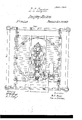
- Figure 1 is a. side elevation of the entire machine supported on xed posts or a fixed foundation, which represents the ,piling or other work around the space to be dredged.
- Fig. 2 is an .end elevation of the same.
- Fig. 3. is a plan view ofthe same.
- a v Tints are' used to adin distinguishing parts,
- the material of the main portions of the frame-work is wood.' The material et? the chains, scoops,f&c., and ⁇ ot ⁇ most of the small work, friction-rollers,
- straps, 8vo. may he iron and steel.
- A isa. fixed 'rame-work, supporting rails or cated by a.
- indi- 'B is a frame supported :en rollers B f', which run on the rails a'.
- the frame B is adapted to traverse on the ways a. a, and may be moved Y by rack and pinion, pulleys', or other ordinary mechanism.
- the framework B carries rails or .ways 'b, provided with stops at each end, as indicated by b'.
- 1 G is a :frame supported-on rollers C,Awhich 'muon theways b.
- the frame C is adapted to traverse on the ways bin a direction transver'se to the positionot' the ways a. It may he moved by'rack and pinion or otherwise.
- the frame 0 carriesa circular track, c.
- D is a frame running on rollers D'; adapted 'gto traverse on the circular track c.
- the frame DI carries-upright guides d, .firmly braced, as represented;A @he drei gingmeclmnism proper is supported between'l these upright gnide's,.and is'adapted te rise and sink therein, while it may be turned round Y by the motion ot' the-tnrning-frame D without Vstopping thc operation ofdredgi-ug. Thismaybe carriedto the right and left 'by the' motion ⁇ cf the transverse frame'G, and may befcarriedforward and back. by theinotionof -the longitudinal frame B.
- vE is a vertical frame-work
- vE is'an-'inclincd i'rame-work, the whole being-rmlycolnected nndbraced sons tooperatc as a single l piece.
- v lt carries stent threaded brackets c..
- buckets h to excavate with very great precision ⁇ at any desired depth, and to be traversed along :as rapidly as may be required in either direc-' A It may-also he presented in any direc' tion.
- the parts Gd Gf which' I- have described as blocks orf'drnms, Iare not .planeon all their faces.
- the arching forni of the guides m eftectually avoids any danger ot' the chains riding on the guides.
- screws fasadaptedl to be operated by hand They may be operated hy steam or other power'through anysuitable. gearing'or other connection; or the screws may be replaced'by racks and--pinions or other ordinary mechanicaldevices for rais,- ing and lowering. Itis simply necessary to that the framework E E' be strongly andv reliably ⁇ at will.
Description
UNrTED. STATES PATENT ()rirrcn.
D.'o.'.fc'itne1nn,`on ortica-G0, ILLINQIS.;
lm PnovED DREDeiNe-mAci-ime,
xSpeciihattion forming part of Letters Patent No. 19,4518, dated June 30, 1868.
To all whom it'anay concern: A
Be it known thaw, DEWITTC. Caserne, ,of Chicago, in4 thezconntyof Cook, inthe State oflllinois, havein vented certainnew and useful Improvements in DredgingMachines,"'and I: do hereby declare that the following Ais a full and exact description thereof.
My improved dredger will serve for dredging. bars, rivers, Src., like-other dredging-man` chines, but is more especially adapted for dredging in `contracted spaces and to detinite points, ,as` in preparing the foundations for piers 'for bridges, sinking shafts of any kind in asot't or diversified bottom,dredging in contracted angles-of docks, and the like.y l
QI will ilrst describe what I consider the best means of carrying out my invention,l and will afterwards desietnatethc voints which I believ.
to .be new therein. v
The accompanyingdrawings form a part ot' this specification.
Figure 1 is a. side elevation of the entire machine supported on xed posts or a fixed foundation, which represents the ,piling or other work around the space to be dredged.
Fig. 2 is an .end elevation of the same. Fig. 3. is a plan view ofthe same. n Similarletters ot'refercnce Indicate/like parts in all the gures. A v Tints are' used to adin distinguishing parts,
and do not indicate material. The material of the main portions of the frame-work is wood.' The material et? the chains, scoops,f&c., and ``ot` most of the small work, friction-rollers,
straps, 8vo., may he iron and steel. A isa. fixed 'rame-work, supporting rails or cated by a.
.A ways a a, having Istops at each' end', as indi- 'B is a frame supported :en rollers B f', which run on the rails a'. The frame B is adapted to traverse on the ways a. a, and may be moved Y by rack and pinion, pulleys', or other ordinary mechanism. (Not represented.) The framework B carries rails or .ways 'b, provided with stops at each end, as indicated by b'. 1 G is a :frame supported-on rollers C,Awhich 'muon theways b. The frame C is adapted to traverse on the ways bin a direction transver'se to the positionot' the ways a. It may he moved by'rack and pinion or otherwise.
The frame 0 carriesa circular track, c.
D is a frame running on rollers D'; adapted 'gto traverse on the circular track c. The frame' D and the parts'snpportcd thereon.'npaybe,
turned round on the circular track c by the nid of rack and pinion or other means. (Not represented.) The frame DI carries-upright guides d, .firmly braced, as represented;A @he drei gingmeclmnism proper is supported between'l these upright gnide's,.and is'adapted te rise and sink therein, while it may be turned round Y by the motion ot' the-tnrning-frame D without Vstopping thc operation ofdredgi-ug. Thismaybe carriedto the right and left 'by the' motion` cf the transverse frame'G, and may befcarriedforward and back. by theinotionof -the longitudinal frame B.
E is a vertical frame-work, and vE is'an-'inclincd i'rame-work, the whole being-rmlycolnected nndbraced sons tooperatc as a single l piece. v lt carries stent threaded brackets c..
which are adapted to receive stout relrlicl'il screws f f, which screws are'snpported at their lower ends in socketsf! onthe traine-work D. 4
These screws may beturnedby hand or other. wise, and thereby the entire frame-work E E and its connections are raised and lowered byA drum or block, G', and the lower shaft carries" a corresponding square-drum or block,G?.-5The length of the flat faces ot' qthese drums corresponds totheiinks ot' thestontend'less pitch Y chains H, which traverse around them and carry' the brackets or shovels h, as represented.- Anti-friction rollersII are mountedon brackets i on the upper inclined face of E', which nid 1in snpportingthe weight of the .pitchchains H H, and` theirploded buckets. The motion of thesechains El4 andthe action of the buckets h in 'excavating the .earth which-they meet in their revolution are analogous to the operation of corresponding' parts in other dredging-nmchines. The means by which they are operated so as not tointerfere with the various motions above provided is novel..l
J is a shaft, rotated by'a--stenm-.engine'ror other suitable power carried on the platform or frame-work D. The' small bevel-gear wheel j,'ii xed on this shaft J, meshes into-a larger 'bevel-gear wheei, @which is mounted on au u'prght sqnare shaft, K, which latter is sur` G G are mount-ed the andv the bucket-s around, the buckets dsnending on the under square keep. the buckets -very Y It' there is aTen'dency "E and I omitting the greatly l'irefer lto employ the inclined frame E',
n tion to the square shaft K, and'thus, through gear-wheel g, .-to. the u pper square dum, G.
.This compelsthe' chains -H h to traverse` continual-ly'- side ci' the .inclined frame,.turning round the lower lsquare block, G'a'ndfrising loaded on the' upperside, bringing up whatever earth is 'taken in lthe shovels or buckets and pouring it into a suitable chute or other receptacle` (Not represented.)
The above-describedl mechanism allows my;
buckets h to excavate with very great precision `at any desired depth, and to be traversed along :as rapidly as may be required in either direc-' A It may-also he presented in any direc' tion.
desirable in practice by turni-ngthe uppe'lmOstframework, D. i
The parts Gd Gfwhich' I- have described as blocks orf'drnms, Iare not .planeon all their faces. Two of the faces .are providedwith stout guides, formed and arranged as indicated bym', which-areadapted to just f ill the space between the two chains H H, and to to press the shovels h to one side from any cause-as'the presence of hard earth on one side, or of bowlders, or some wooden or other obstructionsuch tendency is resisted by thecontac't of the chains against the guides m. The arching forni of the guides m eftectually avoids any danger ot' the chains riding on the guides. i i
'I can operate with sonne success in most lsituations by mounting the shafts G and the connected buckets, &c., on the upright frame inclined frame E';"but I as otherwise mucli'of the advantage properly due to the provisions for raising and lowering,
turning and movingbodily inerery direction, 'cannot be fui?? made available.
AL 'ot'A a corresponding form, each with a spline or longitudinal groove car' the success of this correctly in position.-
as and for the purposes I I have described 'the upright shaft `K as square and the interior of the sleeve L as corvrespondingly formed. It may be-prel'erable in ordinary practice to inake the shaftK cylindrical and to make the interior ot' `the sleeve rying a feather orloose key which'tsn each. This .construction or any move freely upfan'd down on it is compelled to revolve therewith. v
I have represented the screws fasadaptedl to be operated by hand. They may be operated hy steam or other power'through anysuitable. gearing'or other connection; or the screws may be replaced'by racks and--pinions or other ordinary mechanicaldevices for rais,- ing and lowering. Itis simply necessary to that the framework E E' be strongly andv reliably `at will.
`All the movements 'of the several l`rames,B
G, &c., may be effected by steam=power through the agency of ropes and windiasses, pulleys, 0I' the'lik. i
. Having new full'ydescribed my invention,
whatI claim' as new thereiinand desire to secure by Letters -Patent, is as follows:
"-1.1"l`h-e guid-esd-an'd screws f, withjthesha-ft K 'and `bevelpini'on k and: their connections, in
combination. with the verticaliframeworkd Ev and its connections, adapted'v to transmit the power at any elevation, as and'for the purposes herein setforth.- 2. 'The inclined frame-Work E',
`the upright frame E,A as represented, and
adapted to beadjusted.. in theseveral direc.--
tions, and operating the't'lredgin'g mechanism H h. in an inclined position', while the rising and lowering motion maybevertical, as and for the p urposes herein specified. i
3. The guides m, formed and arranged as represented, on the revolving parts Gl?` G?, and
adapted to guide the pitch-chains. H, andconsequentl y to control .very exactly the workingpaths ot' the buckets lL, or their equivalents,
herein'v specified. 1
1). o. caneLeR.
"Witnesses: o
AMEL AW. TINKHAM, E. S. GHEsBRoUGH.
and to provide other .I consider j ,equivalent so longas it 'allows the sleeve L to` the shaft K while 1' portion of my invention and its'. connections supported by means lwhich will allowits elevation to beadjusted mounted on v
Publications (1)
| Publication Number | Publication Date |
|---|---|
| US79448A true US79448A (en) | 1868-06-30 |
Family
ID=2148946
Family Applications (1)
| Application Number | Title | Priority Date | Filing Date |
|---|---|---|---|
| US79448D Expired - Lifetime US79448A (en) | Improved drepqing-m |
Country Status (1)
| Country | Link |
|---|---|
| US (1) | US79448A (en) |
-
0
- US US79448D patent/US79448A/en not_active Expired - Lifetime
Similar Documents
| Publication | Publication Date | Title |
|---|---|---|
| US6029A (en) | Method of directing the scoops in dredging machines | |
| US79448A (en) | Improved drepqing-m | |
| US98848A (en) | Improved dredging-machine | |
| US332042A (en) | Excavating-machine | |
| US502151A (en) | Excavating machine | |
| US618332A (en) | Power dredging-machine | |
| US386309A (en) | Dredging-machine | |
| US530675A (en) | Dredging machine | |
| US443993A (en) | Hoisting apparatus | |
| US309812A (en) | winter | |
| US635798A (en) | Hydraulic dredge. | |
| US275534A (en) | Means for deepening the channels of rivers | |
| US53950A (en) | Improved ditching-machine | |
| US14068A (en) | savage | |
| US268977A (en) | Dredging-machine | |
| US341612A (en) | thompson | |
| US81076A (en) | Improved dredging-machine | |
| US978540A (en) | Dredger. | |
| US4547A (en) | Dredging-machiete | |
| US693266A (en) | Excavator. | |
| US261935A (en) | locke | |
| US340505A (en) | hastings | |
| US357880A (en) | walsh | |
| US383350A (en) | Alberto finks | |
| US48669A (en) | Improved excavators |