US7927263B1 - Exercise equipment with dock-and-lock and spotter platform - Google Patents
Exercise equipment with dock-and-lock and spotter platform Download PDFInfo
- Publication number
- US7927263B1 US7927263B1 US12/827,215 US82721510A US7927263B1 US 7927263 B1 US7927263 B1 US 7927263B1 US 82721510 A US82721510 A US 82721510A US 7927263 B1 US7927263 B1 US 7927263B1
- Authority
- US
- United States
- Prior art keywords
- pivot
- spotter
- post
- step plate
- weight
- Prior art date
- Legal status (The legal status is an assumption and is not a legal conclusion. Google has not performed a legal analysis and makes no representation as to the accuracy of the status listed.)
- Expired - Fee Related
Links
Images


Classifications
-
- A—HUMAN NECESSITIES
- A63—SPORTS; GAMES; AMUSEMENTS
- A63B—APPARATUS FOR PHYSICAL TRAINING, GYMNASTICS, SWIMMING, CLIMBING, OR FENCING; BALL GAMES; TRAINING EQUIPMENT
- A63B21/00—Exercising apparatus for developing or strengthening the muscles or joints of the body by working against a counterforce, with or without measuring devices
- A63B21/06—User-manipulated weights
- A63B21/078—Devices for bench press exercises, e.g. supports, guiding means
-
- A—HUMAN NECESSITIES
- A63—SPORTS; GAMES; AMUSEMENTS
- A63B—APPARATUS FOR PHYSICAL TRAINING, GYMNASTICS, SWIMMING, CLIMBING, OR FENCING; BALL GAMES; TRAINING EQUIPMENT
- A63B21/00—Exercising apparatus for developing or strengthening the muscles or joints of the body by working against a counterforce, with or without measuring devices
- A63B21/40—Interfaces with the user related to strength training; Details thereof
- A63B21/4027—Specific exercise interfaces
- A63B21/4029—Benches specifically adapted for exercising
-
- A—HUMAN NECESSITIES
- A63—SPORTS; GAMES; AMUSEMENTS
- A63B—APPARATUS FOR PHYSICAL TRAINING, GYMNASTICS, SWIMMING, CLIMBING, OR FENCING; BALL GAMES; TRAINING EQUIPMENT
- A63B23/00—Exercising apparatus specially adapted for particular parts of the body
- A63B23/035—Exercising apparatus specially adapted for particular parts of the body for limbs, i.e. upper or lower limbs, e.g. simultaneously
- A63B23/03516—For both arms together or both legs together; Aspects related to the co-ordination between right and left side limbs of a user
- A63B23/03525—Supports for both feet or both hands performing simultaneously the same movement, e.g. single pedal or single handle
-
- Y—GENERAL TAGGING OF NEW TECHNOLOGICAL DEVELOPMENTS; GENERAL TAGGING OF CROSS-SECTIONAL TECHNOLOGIES SPANNING OVER SEVERAL SECTIONS OF THE IPC; TECHNICAL SUBJECTS COVERED BY FORMER USPC CROSS-REFERENCE ART COLLECTIONS [XRACs] AND DIGESTS
- Y10—TECHNICAL SUBJECTS COVERED BY FORMER USPC
- Y10S—TECHNICAL SUBJECTS COVERED BY FORMER USPC CROSS-REFERENCE ART COLLECTIONS [XRACs] AND DIGESTS
- Y10S482/00—Exercise devices
- Y10S482/908—Adjustable
Definitions
- the invention relates to exercise equipment, including weight training equipment, including olympic style weight racks and benches.
- Olympic style weight racks and benches require rigidity and stability while in use. This is accomplished by positively securing the bench to the rack while it is in use.
- the relationship between the user and the rack needs to be adjustable. For example, the positioning of a person doing a flat press is different from a military press. The challenge is to simultaneously achieve a rigid bench that is adjustable relative to the rack.
- olympic weight racks often requires one or more spotters, who need to be positioned relative to the athlete to achieve maximize advantage when assisting the athlete during training.
- Exercises such as an incline or military press require the spotter to be elevated from the floor for maximum efficiency. It is desirable to provide a collapsible spotter platform that can be extended for certain exercises, and retracted for other exercises such as flat presses. squats, and other training routines that do not require an elevated spotter. This provides the most efficient use of space, and the least amount of effort and/or inconvenience for the user.
- the present invention arose during continuing development efforts in the above technology and has application thereto and to other applications.
- FIG. 1 is a perspective view of exercise equipment in accordance with the invention, including a weight training rack and bench.
- FIG. 2 is an end view of the apparatus of FIG. 1 .
- FIG. 3 is a top view of the apparatus of FIG. 1 .
- FIG. 4 is a perspective view of a portion of the apparatus of FIG. 1 .
- FIG. 5 is a bottom view of the apparatus of FIG. 4 .
- FIG. 6 is an exploded perspective view of the apparatus of FIG. 4 .
- FIG. 7 is an isometric view from below of a portion of the apparatus of FIG. 4 .
- FIG. 8 is a side view of the apparatus of FIG. 4 .
- FIG. 9 is an enlarged view of a portion of the apparatus of FIG. 8 taken along line 9 - 9 .
- FIG. 10 is a view like FIG. 9 partially cutaway.
- FIG. 11 is like FIG. 8 and shows a further operational mode.
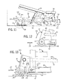
- FIG. 12 is an enlarged view of a portion of the apparatus of FIG. 11 taken along line 12 - 12 .
- FIG. 13 is a view like FIG. 12 , enlarged and partially cutaway.
- FIG. 14 is like FIG. 11 and shows a further operational mode.
- FIG. 15 is an enlarged view of a portion of the apparatus of FIG. 14 taken along line 15 - 15 .
- FIG. 16 is like FIG. 15 , enlarged and partially cutaway.
- FIG. 17 is like FIG. 14 and shows a further operational mode.
- FIG. 18 is an enlarged view of a portion of FIG. 17 , partially cutaway.
- FIG. 19 is an enlarged view of a portion of FIG. 10 , and showing one operational mode.
- FIG. 20 is like FIG. 19 and shows another operational mode.
- FIG. 21 is an enlarged perspective view of a portion of FIG. 1 .
- FIG. 22 is a perspective view from a different angle of the apparatus of FIG. 21 .
- FIG. 23 is a side view of the apparatus of FIG. 21 .
- FIG. 24 is like FIG. 23 and shows sequential operation of the apparatus.
- FIG. 25 is like FIG. 23 and shows the apparatus in an alternate position.
- FIG. 1 shows exercise equipment 30 including a stationary dock 32 and a user support frame 34 engaging the dock in docking relation and releasably lockable thereto at a plurality of selectable locking locations therealong.
- the exercise equipment is a weight training rack and bench
- the stationary dock is a weight rack frame 32 for supporting one or more training weights
- the user support frame is a bench frame 34 for supporting a user bench 36 , for example a seat 38 and a seat back 40 .
- a locking member 42 FIG. 4 , 6 , to be described, releasably locks user support frame 34 to dock 32 .
- the locking member is actuatable between a first locking position 42 a , FIG.
- a user-operated handle 48 is operable, as shown at arrow 50 , FIG. 4 , 14 , to a first condition (e.g. an upward position in the drawings as shown at position 52 , FIG. 14 ) which actuates locking member 42 to its locking position at a selected one of the noted locking locations.
- User-operated handle 48 is operable as shown at arrow 54 , FIG. 11 , to a second condition (e.g. to a downward position as shown at position 56 , FIG.
- User-operated handle 48 has a central neutral position as shown at position 58 in FIG. 8 .
- locking member 42 is in a locking condition when handle 58 is in its neutral position, to be described.
- a roller 60 is mounted to user support frame 34 , preferably at locking member 42 and is movable relative to the user support frame between a first raised position 44 , FIG. 12 , 13 , 15 , 16 , and a second lowered position 46 .
- Roller 60 in the lowered position engages the floor 62 which supports dock 32 and user support frame 34 .
- Roller 60 in its lowered position raises user support frame 34 above floor 62 and actuates locking member 42 to its release position and out of engagement with the dock.
- Roller 60 in its raised position lowers user support frame 34 and actuates locking member 42 to its locking position and enables re-engagement of locking member 42 and the dock.
- user support frame 34 has a lower frame portion 64 having pads such as 66 , 68 on the underside thereof, FIG. 5 , 7 , which rest on floor 62 when roller 60 is in its raised position 44 .
- pads 66 , 68 are lifted above floor 62 , and roller 60 rolls along floor 62 to enable re-positioning of user support frame 34 to a selected one of the noted locking locations along dock 32 , to be described.
- Handle 48 is coupled to roller 60 at locking member 42 by pivoted linkage 70 , FIG. 4 , 6 , connected to user support frame 34 .
- the linkage is provided by a multi-link multi-pivot linkage having: a first link 72 having a first pivot 74 connected to user support frame 34 , a second pivot 76 , and a handle-connection portion 78 connected to handle 48 , preferably rigidly connected thereto, as by welding; a second link 80 having a third pivot 82 connected to user support frame 34 , e.g.
- link 80 pivots clockwise as shown at arrow 92 about pivot 84 such that roller 60 is raised to its raised position 44 .
- link 72 pivots counterclockwise as shown at arrow 94 about pivot 74
- link 90 moves rightwardly as shown at arrow 96 in FIG.
- the handle 48 includes an extension section 100 extending rearwardly therefrom to link 72 , which extension section 100 may be guided for up-down translational movement along slot 102 formed in a bracket 104 attached to the user support frame. Downward movement of handle 48 as shown at arrow 54 in FIG.
- User support frame 34 is movable left-right as shown at arrow 113 , FIG. 13 , along longitudinal direction 114 , FIG. 1 , relative to dock 32 to longitudinally spaced locking locations.
- Roller 60 is movable relative to user support frame 34 between the noted raised and lowered positions 44 and 46 , transversely of longitudinal direction 114 .
- Roller 60 is provided by a set of one or more rollers, such as a bobbin or spindle having rollers 60 a and 60 b connected by a central axle 60 c .
- a second set of one or more rollers such as 120 , 122 are journaled to user support frame 34 at support leg 124 and are longitudinally spaced from the first set of one or more rollers 60 .
- User support frame 34 rolls along floor 62 on the noted sets of rollers 60 , 120 , 122 when the first set of rollers 60 is in the noted lowered position 46 .
- the first and second sets of rollers 60 and 120 , 122 are longitudinally spaced along user support frame 34 at longitudinally distally opposite ends 126 and 128 thereof, respectively.
- a third set of one or more rollers such as 130 , 132 are journaled to user support frame 34 at outrigger legs 134 and 136 , FIG.
- the noted third set of rollers 130 , 132 are preferably provided by a pair of outrigger rollers laterally spaced outwardly of the noted first set of rollers 60 a , 60 b therebetween.
- Dock 32 preferably includes an anchor portion 144 , FIGS. 3-5 , having a locking tongue 146 extending longitudinally therefrom along axis 114 and providing the noted plurality of locking locations longitudinally spaced along the tongue.
- Tongue 146 has a plurality of detents 148 longitudinally spaced therealong and providing the noted locking locations.
- the detents are preferably provided by slots longitudinally spaced along tongue 146 .
- the locking member includes a locking pin 150 , FIG. 10 , 19 , 20 , mounted to the user support frame at lower portion 64 and lowered into a respective slot 148 , FIG. 20 , upon lowering of the left end 126 of user support frame 34 in response to raising of roller 60 .
- Locking pin 150 is biased downwardly toward a respective slot 148 by spring 152 which also provides lost motion when locking pin 150 is not aligned with a respective slot 148 as shown in FIG. 19 .
- User support frame 34 is then moved left or right as shown at arrow 113 along longitudinal direction 114 until pin 150 aligns with a slot 148 and moves downwardly thereinto, FIG. 20 , due to the bias of spring 152 , to thus lock user support frame 34 to tongue 146 of dock 32 .
- Roller 60 is preferably provided by the noted pair of laterally spaced rollers 60 a and 60 b straddling tongue 146 extending longitudinally therebetween.
- Roller 60 is mounted to user support frame 34 by bracket or link 80 having the noted pivot 82 connected to the user support frame 34 , and the noted pivot 86 journaling roller 60 , and the noted pivot 88 coupled to handle 48 through handle linkage 90 , 72 , 100 .
- the apparatus provides an olympic caliber weight training rack and bench including weight rack frame 32 for supporting one or more training weights, and bench frame 34 supporting a user bench 36 which may include seat 38 and seat back 40 .
- the angle of seat back 40 may be adjusted by support arms 39 , as is standard.
- the noted weight training exercise equipment 30 includes the noted weight rack frame 32 having a plurality of laterally spaced upstanding support posts such as 180 , 182 , FIGS. 1-3 .
- a pair of collapsible spotter platforms 184 and 186 are provided, each mounted to a respective post 180 , 182 .
- Spotter platforms 184 and 186 are laterally spaced by an open lateral gap 188 therebetween, without a lateral cross-brace between the spotter platforms, to facilitate ease of step-through for a spotter.
- Each spotter platform 184 , 186 is pivotally mounted to its respective post 180 , 182 for pivotal movement between a horizontal position, FIG. 1 , 2 , 22 , 23 , for supporting a spotter thereon, and a collapsed position, FIG. 25 , occupying less horizontal area than in the horizontal position.
- Each spotter platform includes a step plate, such as 190 , FIGS. 21-25 , having a first pivot 192 pivotally mounted to its respective post, and a second pivot 194 , and further includes a triangulated hypotenuse leg 196 having a first end 198 pivoted to step plate 190 at pivot 194 , and having a second end 200 having a cross-bar or T-bar 202 translationally slidable along the post.
- the spotter platform further includes a bracket 204 mounted to the post and having a pivot mount at 206 pivotally mounting the step plate at pivot 192 and having a guide track channel 208 guiding the noted second end 200 of hypotenuse leg 196 at transverse T-bar 202 therealong.
- the guide track channel preferably includes a pair of spaced channels 208 a and 208 b each guiding a respective end of T-bar 202 at 202 a and 202 b , respectively.
- the guide track channel extends obtusely relative to upstanding post 182 and relative to the noted horizontal position, FIG. 22 , 23 , of the spotter platform 190 .
- Guide track channel 208 extends between upper and lower ends 210 and 212 .
- Upper end 210 is at a vertically higher level than pivot 192 .
- Lower end 212 is at a vertically lower level than pivot 192 .
- Lower end 212 is at a vertically lower level than pivot 192 by a distance selected to provide an angle of at least 20°, and preferably about 25°, between hypotenuse leg 196 and step plate 190 when the step plate is in the noted horizontal position, FIG. 23 .
- Guide track channel 208 extends nonrectilinearly between upper and lower ends 210 and 212 .
- the guide track channel has upper and lower sections 214 and 216 meeting at an angled junction 218 .
- Lower section 216 is longer than upper section 214 .
- Angled junction 218 is preferably horizontally aligned with pivot 192 .
Landscapes
- Health & Medical Sciences (AREA)
- Orthopedic Medicine & Surgery (AREA)
- General Health & Medical Sciences (AREA)
- Physical Education & Sports Medicine (AREA)
- Life Sciences & Earth Sciences (AREA)
- Biophysics (AREA)
- Special Chairs (AREA)
- Rehabilitation Tools (AREA)
Abstract
Description
Claims (4)
Priority Applications (1)
| Application Number | Priority Date | Filing Date | Title |
|---|---|---|---|
| US12/827,215 US7927263B1 (en) | 2008-05-27 | 2010-06-30 | Exercise equipment with dock-and-lock and spotter platform |
Applications Claiming Priority (2)
| Application Number | Priority Date | Filing Date | Title |
|---|---|---|---|
| US12/127,094 US7753830B1 (en) | 2008-05-27 | 2008-05-27 | Exercise equipment with dock-and-lock and spotter platform |
| US12/827,215 US7927263B1 (en) | 2008-05-27 | 2010-06-30 | Exercise equipment with dock-and-lock and spotter platform |
Related Parent Applications (1)
| Application Number | Title | Priority Date | Filing Date |
|---|---|---|---|
| US12/127,094 Division US7753830B1 (en) | 2008-05-27 | 2008-05-27 | Exercise equipment with dock-and-lock and spotter platform |
Publications (1)
| Publication Number | Publication Date |
|---|---|
| US7927263B1 true US7927263B1 (en) | 2011-04-19 |
Family
ID=42314063
Family Applications (2)
| Application Number | Title | Priority Date | Filing Date |
|---|---|---|---|
| US12/127,094 Active 2028-08-13 US7753830B1 (en) | 2008-05-27 | 2008-05-27 | Exercise equipment with dock-and-lock and spotter platform |
| US12/827,215 Expired - Fee Related US7927263B1 (en) | 2008-05-27 | 2010-06-30 | Exercise equipment with dock-and-lock and spotter platform |
Family Applications Before (1)
| Application Number | Title | Priority Date | Filing Date |
|---|---|---|---|
| US12/127,094 Active 2028-08-13 US7753830B1 (en) | 2008-05-27 | 2008-05-27 | Exercise equipment with dock-and-lock and spotter platform |
Country Status (1)
| Country | Link |
|---|---|
| US (2) | US7753830B1 (en) |
Cited By (7)
| Publication number | Priority date | Publication date | Assignee | Title |
|---|---|---|---|---|
| US8808151B1 (en) | 2012-01-04 | 2014-08-19 | Brunswick Corporation | Exercise equipment and adjustable band peg assemblies for exercise equipment |
| US8998782B1 (en) | 2012-12-13 | 2015-04-07 | Brunswick Corporation | Exercise equipment and adjustable band peg assemblies for exercise equipment |
| US8998781B1 (en) | 2012-12-13 | 2015-04-07 | Brunswick Corporation | Exercise equipment having adjustable band pegs |
| USD731601S1 (en) * | 2013-02-27 | 2015-06-09 | 12Novem Industries, Inc. | Wheelchair-accessible exercise platform |
| US20170216656A1 (en) * | 2016-02-02 | 2017-08-03 | Specialty Fitness Systems, Llc | Weight Bench Centering Device |
| US10463907B2 (en) * | 2017-04-18 | 2019-11-05 | Steven E. English | Bench press apparatus with spotter platform |
| US20260021338A1 (en) * | 2024-07-17 | 2026-01-22 | Vonrang International Corporation | Weight bench |
Families Citing this family (55)
| Publication number | Priority date | Publication date | Assignee | Title |
|---|---|---|---|---|
| US7878958B2 (en) * | 2006-01-05 | 2011-02-01 | Rogers Athletic Company | Weightlifting system with spotter platform |
| US7918771B2 (en) | 2006-01-05 | 2011-04-05 | Rogers Athletic Company | Weightlifting system with omni directional weight arms |
| US9248333B2 (en) * | 2012-05-01 | 2016-02-02 | Rogers Athletic Company | Adjustable support for exercise system |
| USD678963S1 (en) * | 2012-08-06 | 2013-03-26 | Robert William James | Multifunctional weight bench |
| US10016646B2 (en) * | 2012-09-14 | 2018-07-10 | BodyForce, Inc. | Multifunctional exercise machines |
| US9254409B2 (en) | 2013-03-14 | 2016-02-09 | Icon Health & Fitness, Inc. | Strength training apparatus with flywheel and related methods |
| US20160074695A1 (en) * | 2013-05-15 | 2016-03-17 | Ki Won Lee | Fitness structure |
| US9278246B2 (en) * | 2013-09-16 | 2016-03-08 | Dynamic Fitness & Strength, LLC | Modular upright for fitness apparatus |
| EP3623020B1 (en) | 2013-12-26 | 2024-05-01 | iFIT Inc. | Magnetic resistance mechanism in a cable machine |
| WO2015138339A1 (en) | 2014-03-10 | 2015-09-17 | Icon Health & Fitness, Inc. | Pressure sensor to quantify work |
| EP3326700B1 (en) * | 2014-03-11 | 2019-02-06 | Cybex International, Inc. | Arm curl exercise apparatus |
| US10166435B2 (en) | 2014-03-11 | 2019-01-01 | Cybex International, Inc. | Back extension exercise apparatus |
| US20150352395A1 (en) * | 2014-06-05 | 2015-12-10 | Trever Gregory | Surface mounted modular exercise device |
| US10426989B2 (en) | 2014-06-09 | 2019-10-01 | Icon Health & Fitness, Inc. | Cable system incorporated into a treadmill |
| US9381393B1 (en) * | 2014-09-04 | 2016-07-05 | Daniel Mathew Gonzalez | Suspended weight barbell attachment |
| US10258828B2 (en) | 2015-01-16 | 2019-04-16 | Icon Health & Fitness, Inc. | Controls for an exercise device |
| US9555274B1 (en) * | 2015-02-11 | 2017-01-31 | Brunswick Corporation | Seat adjustment devices and exercise apparatuses having seat adjustment devices |
| US9907991B2 (en) * | 2015-07-08 | 2018-03-06 | Specialty Fitness Systems, Llc | Fitness bar catch mechanism |
| US10953305B2 (en) | 2015-08-26 | 2021-03-23 | Icon Health & Fitness, Inc. | Strength exercise mechanisms |
| RU2620488C1 (en) * | 2016-01-27 | 2017-05-25 | Дмитрий Давидович Слободник | Press machine |
| US10086226B2 (en) * | 2016-02-29 | 2018-10-02 | Brunswick Corporation | Energy absorbing weight bar support assemblies for exercise equipment |
| US10293211B2 (en) | 2016-03-18 | 2019-05-21 | Icon Health & Fitness, Inc. | Coordinated weight selection |
| US10625137B2 (en) | 2016-03-18 | 2020-04-21 | Icon Health & Fitness, Inc. | Coordinated displays in an exercise device |
| US10272317B2 (en) | 2016-03-18 | 2019-04-30 | Icon Health & Fitness, Inc. | Lighted pace feature in a treadmill |
| US10493349B2 (en) | 2016-03-18 | 2019-12-03 | Icon Health & Fitness, Inc. | Display on exercise device |
| US10561894B2 (en) | 2016-03-18 | 2020-02-18 | Icon Health & Fitness, Inc. | Treadmill with removable supports |
| US10252109B2 (en) | 2016-05-13 | 2019-04-09 | Icon Health & Fitness, Inc. | Weight platform treadmill |
| US20170340915A1 (en) * | 2016-05-27 | 2017-11-30 | SCULPTABODY, Inc. | Portable exercise equipment |
| US10471299B2 (en) | 2016-07-01 | 2019-11-12 | Icon Health & Fitness, Inc. | Systems and methods for cooling internal exercise equipment components |
| US10441844B2 (en) | 2016-07-01 | 2019-10-15 | Icon Health & Fitness, Inc. | Cooling systems and methods for exercise equipment |
| US9750971B1 (en) * | 2016-09-01 | 2017-09-05 | Damon J. Humphrey | Pedal activated lift advantage weight lifting bench apparatus |
| US10500473B2 (en) | 2016-10-10 | 2019-12-10 | Icon Health & Fitness, Inc. | Console positioning |
| US10376736B2 (en) | 2016-10-12 | 2019-08-13 | Icon Health & Fitness, Inc. | Cooling an exercise device during a dive motor runway condition |
| US10661114B2 (en) | 2016-11-01 | 2020-05-26 | Icon Health & Fitness, Inc. | Body weight lift mechanism on treadmill |
| TWI646997B (en) | 2016-11-01 | 2019-01-11 | 美商愛康運動與健康公司 | Distance sensor for console positioning |
| TWI680782B (en) | 2016-12-05 | 2020-01-01 | 美商愛康運動與健康公司 | Offsetting treadmill deck weight during operation |
| US10806963B2 (en) * | 2017-02-10 | 2020-10-20 | Rogers Athletic Company, Inc. | Storable bench |
| JP6957655B2 (en) * | 2017-06-26 | 2021-11-02 | ノーティラス インコーポレイテッド | Storable exercise bench |
| TWI722450B (en) | 2017-08-16 | 2021-03-21 | 美商愛康運動與健康公司 | System for opposing axial impact loading in a motor |
| AT520504A1 (en) * | 2017-10-10 | 2019-04-15 | Bernd Josef Polajner | exerciser |
| US11660491B2 (en) | 2017-11-02 | 2023-05-30 | Coulter Ventures, Llc. | Weightlifting assembly |
| US11541268B2 (en) | 2017-12-04 | 2023-01-03 | Joshua AUERBACH | Jerk block, jerk block set up, and method of using the jerk block set up |
| US10729965B2 (en) | 2017-12-22 | 2020-08-04 | Icon Health & Fitness, Inc. | Audible belt guide in a treadmill |
| US12053674B1 (en) * | 2018-04-12 | 2024-08-06 | AI Incorporated | Smart gym equipment |
| USD886920S1 (en) | 2018-06-05 | 2020-06-09 | Coulter Ventures, Llc. | Set of wall mounts for exercise rack |
| USD879216S1 (en) * | 2018-06-05 | 2020-03-24 | Coulter Ventures, Llc. | Wall mount |
| USD888851S1 (en) | 2018-06-05 | 2020-06-30 | Coulter Ventures, Llc. | Wall mounted exercise rack |
| WO2021222686A1 (en) | 2020-05-01 | 2021-11-04 | Sorin Albert | Adjustable support attachment apparatus and methods of using same |
| IT202000015997A1 (en) * | 2020-07-02 | 2022-01-02 | Andrea Maria Quarto | ADAPTER DEVICE FOR A WEIGHT LIFTING BENCH |
| US11229815B1 (en) * | 2020-07-24 | 2022-01-25 | Douglas B. Duval | Exercise equipment and method of using the same |
| US12569709B2 (en) | 2022-02-10 | 2026-03-10 | Tonal Systems, Inc. | Dual motor exercise machine |
| CN116829232A (en) | 2020-12-15 | 2023-09-29 | 托纳系统公司 | Floor-based exercise machine construction |
| US12558588B2 (en) * | 2021-01-11 | 2026-02-24 | Willy Wei Yu Ho | Pivot stopping mechanism |
| US12465802B2 (en) * | 2021-04-12 | 2025-11-11 | Albert Sorin | Hang row pendulum apparatus and methods of using same |
| USD980354S1 (en) * | 2021-10-29 | 2023-03-07 | Xavork Wooliand Inc | Fitness equipment |
Citations (35)
| Publication number | Priority date | Publication date | Assignee | Title |
|---|---|---|---|---|
| US1826055A (en) * | 1930-04-28 | 1931-10-06 | Albert B Cornwall | Shelving |
| US1905908A (en) * | 1931-06-25 | 1933-04-25 | Orin E Karnes | Display stand |
| US1941838A (en) * | 1929-06-21 | 1934-01-02 | Herbert B Hyams | Display device |
| US2855981A (en) * | 1957-03-14 | 1958-10-14 | Dierikx Petrus | Folding counter stool |
| US3167037A (en) * | 1961-08-23 | 1965-01-26 | M & D Store Fixtures Inc | Merchandise display shelf |
| US3463433A (en) * | 1967-08-08 | 1969-08-26 | Grant Pulley & Hardware Corp | Adjustable bracket |
| US4805863A (en) * | 1987-03-30 | 1989-02-21 | Armstrong Store Fixture Corporation | Brace and shelf support assembly |
| US4927107A (en) * | 1989-03-01 | 1990-05-22 | Ramon Mateo Maria | Support for reclinable boards |
| US4998484A (en) * | 1989-09-11 | 1991-03-12 | Niche Design, Inc. | Versatile wall mount folding table |
| US5020799A (en) * | 1988-08-09 | 1991-06-04 | Chang Yong Hong | Folding billiard table |
| US5151072A (en) * | 1991-05-14 | 1992-09-29 | Cone Dennis E | Free weight barbell spotting and racking machine |
| US5649886A (en) | 1996-04-10 | 1997-07-22 | Danylieko; Richard A. | Workout bench |
| US5954619A (en) * | 1998-02-24 | 1999-09-21 | Petrone; Charles M. | Apparatus for storage and presentation of exercise dumbbells |
| US6186926B1 (en) * | 1999-04-22 | 2001-02-13 | Northland Industries, Inc. | Seated abdominal exercise machine |
| US6334400B1 (en) * | 2000-05-04 | 2002-01-01 | Chou-Chin Nien | Foldable table |
| US6343834B1 (en) * | 2000-05-01 | 2002-02-05 | Hide-A-Seat Manufacturing Corp. | Collapsible wall mounted seat |
| US6605023B1 (en) | 2000-10-16 | 2003-08-12 | Conner Athletic Products, Inc. | Adjustable weightlifting bend |
| US6685604B1 (en) * | 1999-09-09 | 2004-02-03 | Anghel Muscocea | Muscle-building apparatus for press-ups |
| US6685601B1 (en) * | 2000-11-17 | 2004-02-03 | Jeffrey M. Knapp | Compact weightlifting system with safety cage |
| US20050183640A1 (en) * | 2004-02-20 | 2005-08-25 | Standalone, Inc. | Expandable and collapsible table |
| US20050209068A1 (en) * | 2004-03-19 | 2005-09-22 | Lincoln Bret M | Straddle stretching apparatus |
| US6966872B2 (en) | 2002-10-04 | 2005-11-22 | Paul William Eschenbach | Articulating abdominal exercise bench |
| US7147594B1 (en) | 2004-12-21 | 2006-12-12 | Vittone William M | System for positioning user support of exercise device |
| US7204791B1 (en) | 2003-03-07 | 2007-04-17 | Brunswick Corporation | One handed dock and lock exercise station |
| US7210414B1 (en) * | 2003-12-16 | 2007-05-01 | Joseph Barone | Folding table for mounting on handrail |
| US20070155597A1 (en) | 2006-01-05 | 2007-07-05 | Rogers Athletic Company | Weightlifting system with spotter platform |
| US7331912B2 (en) | 2003-06-27 | 2008-02-19 | Keiser Corporation | Adjustable bench |
| US20080076641A1 (en) * | 2006-09-25 | 2008-03-27 | Sheehan Thomas D | Exercise Bench |
| US20090079243A1 (en) * | 2007-09-24 | 2009-03-26 | Kunzler Patrik A | Seat With 3D Motion Interface |
| US20090143203A1 (en) * | 2000-11-17 | 2009-06-04 | Knapp Jeffrey M | Compact weightlifting frame system |
| US20090203505A1 (en) * | 2008-02-11 | 2009-08-13 | Kroll Ryan M | Exercise equipment safety apparatuses |
| US7585259B2 (en) | 2005-01-24 | 2009-09-08 | Maxrep Benchcrafters Llc | Weightlifting spotting machine |
| US7632221B1 (en) * | 2006-10-23 | 2009-12-15 | Scott Kolander | Cable cross trainer apparatus |
| US7731642B2 (en) * | 2008-03-07 | 2010-06-08 | Senoh Kabushiki Kaisha | Training apparatus |
| US7757615B2 (en) * | 2004-03-23 | 2010-07-20 | Utilimaster Corporation | Shelf assembly |
-
2008
- 2008-05-27 US US12/127,094 patent/US7753830B1/en active Active
-
2010
- 2010-06-30 US US12/827,215 patent/US7927263B1/en not_active Expired - Fee Related
Patent Citations (35)
| Publication number | Priority date | Publication date | Assignee | Title |
|---|---|---|---|---|
| US1941838A (en) * | 1929-06-21 | 1934-01-02 | Herbert B Hyams | Display device |
| US1826055A (en) * | 1930-04-28 | 1931-10-06 | Albert B Cornwall | Shelving |
| US1905908A (en) * | 1931-06-25 | 1933-04-25 | Orin E Karnes | Display stand |
| US2855981A (en) * | 1957-03-14 | 1958-10-14 | Dierikx Petrus | Folding counter stool |
| US3167037A (en) * | 1961-08-23 | 1965-01-26 | M & D Store Fixtures Inc | Merchandise display shelf |
| US3463433A (en) * | 1967-08-08 | 1969-08-26 | Grant Pulley & Hardware Corp | Adjustable bracket |
| US4805863A (en) * | 1987-03-30 | 1989-02-21 | Armstrong Store Fixture Corporation | Brace and shelf support assembly |
| US5020799A (en) * | 1988-08-09 | 1991-06-04 | Chang Yong Hong | Folding billiard table |
| US4927107A (en) * | 1989-03-01 | 1990-05-22 | Ramon Mateo Maria | Support for reclinable boards |
| US4998484A (en) * | 1989-09-11 | 1991-03-12 | Niche Design, Inc. | Versatile wall mount folding table |
| US5151072A (en) * | 1991-05-14 | 1992-09-29 | Cone Dennis E | Free weight barbell spotting and racking machine |
| US5649886A (en) | 1996-04-10 | 1997-07-22 | Danylieko; Richard A. | Workout bench |
| US5954619A (en) * | 1998-02-24 | 1999-09-21 | Petrone; Charles M. | Apparatus for storage and presentation of exercise dumbbells |
| US6186926B1 (en) * | 1999-04-22 | 2001-02-13 | Northland Industries, Inc. | Seated abdominal exercise machine |
| US6685604B1 (en) * | 1999-09-09 | 2004-02-03 | Anghel Muscocea | Muscle-building apparatus for press-ups |
| US6343834B1 (en) * | 2000-05-01 | 2002-02-05 | Hide-A-Seat Manufacturing Corp. | Collapsible wall mounted seat |
| US6334400B1 (en) * | 2000-05-04 | 2002-01-01 | Chou-Chin Nien | Foldable table |
| US6605023B1 (en) | 2000-10-16 | 2003-08-12 | Conner Athletic Products, Inc. | Adjustable weightlifting bend |
| US20090143203A1 (en) * | 2000-11-17 | 2009-06-04 | Knapp Jeffrey M | Compact weightlifting frame system |
| US6685601B1 (en) * | 2000-11-17 | 2004-02-03 | Jeffrey M. Knapp | Compact weightlifting system with safety cage |
| US6966872B2 (en) | 2002-10-04 | 2005-11-22 | Paul William Eschenbach | Articulating abdominal exercise bench |
| US7204791B1 (en) | 2003-03-07 | 2007-04-17 | Brunswick Corporation | One handed dock and lock exercise station |
| US7331912B2 (en) | 2003-06-27 | 2008-02-19 | Keiser Corporation | Adjustable bench |
| US7210414B1 (en) * | 2003-12-16 | 2007-05-01 | Joseph Barone | Folding table for mounting on handrail |
| US20050183640A1 (en) * | 2004-02-20 | 2005-08-25 | Standalone, Inc. | Expandable and collapsible table |
| US20050209068A1 (en) * | 2004-03-19 | 2005-09-22 | Lincoln Bret M | Straddle stretching apparatus |
| US7757615B2 (en) * | 2004-03-23 | 2010-07-20 | Utilimaster Corporation | Shelf assembly |
| US7147594B1 (en) | 2004-12-21 | 2006-12-12 | Vittone William M | System for positioning user support of exercise device |
| US7585259B2 (en) | 2005-01-24 | 2009-09-08 | Maxrep Benchcrafters Llc | Weightlifting spotting machine |
| US20070155597A1 (en) | 2006-01-05 | 2007-07-05 | Rogers Athletic Company | Weightlifting system with spotter platform |
| US20080076641A1 (en) * | 2006-09-25 | 2008-03-27 | Sheehan Thomas D | Exercise Bench |
| US7632221B1 (en) * | 2006-10-23 | 2009-12-15 | Scott Kolander | Cable cross trainer apparatus |
| US20090079243A1 (en) * | 2007-09-24 | 2009-03-26 | Kunzler Patrik A | Seat With 3D Motion Interface |
| US20090203505A1 (en) * | 2008-02-11 | 2009-08-13 | Kroll Ryan M | Exercise equipment safety apparatuses |
| US7731642B2 (en) * | 2008-03-07 | 2010-06-08 | Senoh Kabushiki Kaisha | Training apparatus |
Non-Patent Citations (2)
| Title |
|---|
| Exhibit A, Admitted Prior Art, at least as early as Jun. 14, 2007. |
| Exhibit B, Admitted Prior Art, at least as early as Feb. 19, 2007. |
Cited By (10)
| Publication number | Priority date | Publication date | Assignee | Title |
|---|---|---|---|---|
| US8808151B1 (en) | 2012-01-04 | 2014-08-19 | Brunswick Corporation | Exercise equipment and adjustable band peg assemblies for exercise equipment |
| US8998782B1 (en) | 2012-12-13 | 2015-04-07 | Brunswick Corporation | Exercise equipment and adjustable band peg assemblies for exercise equipment |
| US8998781B1 (en) | 2012-12-13 | 2015-04-07 | Brunswick Corporation | Exercise equipment having adjustable band pegs |
| US9327158B1 (en) | 2012-12-13 | 2016-05-03 | Brunswick Corporation | Exercise equipment and adjustable band peg assemblies for exercise equipment |
| US9333384B1 (en) | 2012-12-13 | 2016-05-10 | Brunswick Corporation | Exercise equipment having adjustable band pegs |
| USD731601S1 (en) * | 2013-02-27 | 2015-06-09 | 12Novem Industries, Inc. | Wheelchair-accessible exercise platform |
| US20170216656A1 (en) * | 2016-02-02 | 2017-08-03 | Specialty Fitness Systems, Llc | Weight Bench Centering Device |
| US10864404B2 (en) * | 2016-02-02 | 2020-12-15 | Specialty Fitness Systems, Llc | Weight bench centering device |
| US10463907B2 (en) * | 2017-04-18 | 2019-11-05 | Steven E. English | Bench press apparatus with spotter platform |
| US20260021338A1 (en) * | 2024-07-17 | 2026-01-22 | Vonrang International Corporation | Weight bench |
Also Published As
| Publication number | Publication date |
|---|---|
| US7753830B1 (en) | 2010-07-13 |
Similar Documents
| Publication | Publication Date | Title |
|---|---|---|
| US7927263B1 (en) | Exercise equipment with dock-and-lock and spotter platform | |
| US11007399B1 (en) | Retractable wall mounted weightlifting bench system | |
| AU772261B2 (en) | Reformer exercise apparatus | |
| US6527685B2 (en) | Reformer exercise apparatus | |
| US9108079B2 (en) | Exercise table | |
| US7104937B2 (en) | Foldable transportable multiple function pilates exercise method and apparatus | |
| US6371895B1 (en) | Reformer exercise apparatus | |
| US7294098B2 (en) | Carriage for a collapsible reformer exercise apparatus | |
| US8834329B2 (en) | Bench press combining full body safety bars and gliding bar holder arms | |
| US20030195095A1 (en) | Reformer exercise apparatus | |
| US20080248935A1 (en) | Foldable Transportable Multiple Function Pilates Exercise Apparatus and Method | |
| EP4424388B1 (en) | Exercise machines for weight training | |
| US12324944B2 (en) | Exercise machine | |
| US12207732B2 (en) | Exercise apparatus | |
| AU2004200589B2 (en) | Reformer exercise apparatus | |
| US20260124492A1 (en) | Exercise machines for weight training | |
| CN120265360A (en) | Pulley assembly and counterweight arm |
Legal Events
| Date | Code | Title | Description |
|---|---|---|---|
| FEPP | Fee payment procedure |
Free format text: PAYOR NUMBER ASSIGNED (ORIGINAL EVENT CODE: ASPN); ENTITY STATUS OF PATENT OWNER: LARGE ENTITY |
|
| STCF | Information on status: patent grant |
Free format text: PATENTED CASE |
|
| AS | Assignment |
Owner name: JPMORGAN CHASE BANK, N.A., AS ADMINISTRATIVE AGENT Free format text: SECURITY AGREEMENT;ASSIGNORS:BRUNSWICK CORPORATION;ATTWOOD CORPORATION;BOSTON WHALER, INC.;AND OTHERS;REEL/FRAME:026072/0239 Effective date: 20110321 |
|
| AS | Assignment |
Owner name: JPMORGAN CHASE BANK, N.A., AS ADMINISTRATIVE AGENT Free format text: SECURITY INTEREST;ASSIGNORS:BRUNSWICK CORPORATION;BRUNSWICK BOWLING & BILLIARDS CORP.;LEISERV, LLC;AND OTHERS;REEL/FRAME:033263/0281 Effective date: 20140626 |
|
| FPAY | Fee payment |
Year of fee payment: 4 |
|
| AS | Assignment |
Owner name: BOSTON WHALER, INC., ILLINOIS Free format text: RELEASE BY SECURED PARTY;ASSIGNOR:JPMORGAN CHASE BANK, N.A.;REEL/FRAME:034794/0257 Effective date: 20141224 Owner name: BRUNSWICK LEISURE BOAT COMPANY, LLC, ILLINOIS Free format text: RELEASE BY SECURED PARTY;ASSIGNOR:JPMORGAN CHASE BANK, N.A.;REEL/FRAME:034794/0257 Effective date: 20141224 Owner name: BRUNSWICK COMMERCIAL & GOVERNMENT PRODUCTS, INC., Free format text: RELEASE BY SECURED PARTY;ASSIGNOR:JPMORGAN CHASE BANK, N.A.;REEL/FRAME:034794/0257 Effective date: 20141224 Owner name: BRUNSWICK COMMERCIAL & GOVERNMENT PRODUCTS, INC., Free format text: RELEASE BY SECURED PARTY;ASSIGNOR:JPMORGAN CHASE BANK, N.A.;REEL/FRAME:034794/0300 Effective date: 20141226 Owner name: BRUNSWICK CORPORATION, ILLINOIS Free format text: RELEASE BY SECURED PARTY;ASSIGNOR:JPMORGAN CHASE BANK, N.A.;REEL/FRAME:034794/0300 Effective date: 20141226 Owner name: BRUNSWICK FAMILY BOAT CO. INC., ILLINOIS Free format text: RELEASE BY SECURED PARTY;ASSIGNOR:JPMORGAN CHASE BANK, N.A.;REEL/FRAME:034794/0300 Effective date: 20141226 Owner name: BOSTON WHALER, INC., ILLINOIS Free format text: RELEASE BY SECURED PARTY;ASSIGNOR:JPMORGAN CHASE BANK, N.A.;REEL/FRAME:034794/0300 Effective date: 20141226 Owner name: LUND BOAT COMPANY, ILLINOIS Free format text: RELEASE BY SECURED PARTY;ASSIGNOR:JPMORGAN CHASE BANK, N.A.;REEL/FRAME:034794/0257 Effective date: 20141224 Owner name: ATTWOOD CORPORATION, ILLINOIS Free format text: RELEASE BY SECURED PARTY;ASSIGNOR:JPMORGAN CHASE BANK, N.A.;REEL/FRAME:034794/0300 Effective date: 20141226 Owner name: BRUNSWICK BOWLING & BILLIARDS CORPORATION, ILLINOI Free format text: RELEASE BY SECURED PARTY;ASSIGNOR:JPMORGAN CHASE BANK, N.A.;REEL/FRAME:034794/0300 Effective date: 20141226 Owner name: BRUNSWICK CORPORATION, ILLINOIS Free format text: RELEASE BY SECURED PARTY;ASSIGNOR:JPMORGAN CHASE BANK, N.A.;REEL/FRAME:034794/0257 Effective date: 20141224 Owner name: BRUNSWICK LEISURE BOAT COMPANY, LLC, ILLINOIS Free format text: RELEASE BY SECURED PARTY;ASSIGNOR:JPMORGAN CHASE BANK, N.A.;REEL/FRAME:034794/0300 Effective date: 20141226 Owner name: BRUNSWICK BOWLING & BILLIARDS CORPORATION, ILLINOI Free format text: RELEASE BY SECURED PARTY;ASSIGNOR:JPMORGAN CHASE BANK, N.A.;REEL/FRAME:034794/0257 Effective date: 20141224 Owner name: LUND BOAT COMPANY, ILLINOIS Free format text: RELEASE BY SECURED PARTY;ASSIGNOR:JPMORGAN CHASE BANK, N.A.;REEL/FRAME:034794/0300 Effective date: 20141226 Owner name: LAND 'N' SEA DISTRIBUTING, INC., ILLINOIS Free format text: RELEASE BY SECURED PARTY;ASSIGNOR:JPMORGAN CHASE BANK, N.A.;REEL/FRAME:034794/0300 Effective date: 20141226 |
|
| MAFP | Maintenance fee payment |
Free format text: PAYMENT OF MAINTENANCE FEE, 8TH YEAR, LARGE ENTITY (ORIGINAL EVENT CODE: M1552); ENTITY STATUS OF PATENT OWNER: LARGE ENTITY Year of fee payment: 8 |
|
| AS | Assignment |
Owner name: LIFE FITNESS, LLC, ILLINOIS Free format text: ASSIGNMENT OF ASSIGNORS INTEREST;ASSIGNOR:BRUNSWICK CORPORATION;REEL/FRAME:049585/0893 Effective date: 20190624 |
|
| AS | Assignment |
Owner name: PNC BANK, NATIONAL ASSOCIATION, UNITED STATES Free format text: SECURITY AGREEMENT;ASSIGNOR:LIFE FITNESS, LLC;REEL/FRAME:049629/0124 Effective date: 20190627 |
|
| AS | Assignment |
Owner name: PLC AGENT LLC, AS COLLATERAL AGENT, MASSACHUSETTS Free format text: NOTICE OF GRANT OF SECURITY INTEREST IN PATENTS;ASSIGNOR:LIFE FITNESS, LLC;REEL/FRAME:059861/0208 Effective date: 20220415 |
|
| FEPP | Fee payment procedure |
Free format text: MAINTENANCE FEE REMINDER MAILED (ORIGINAL EVENT CODE: REM.); ENTITY STATUS OF PATENT OWNER: LARGE ENTITY |
|
| LAPS | Lapse for failure to pay maintenance fees |
Free format text: PATENT EXPIRED FOR FAILURE TO PAY MAINTENANCE FEES (ORIGINAL EVENT CODE: EXP.); ENTITY STATUS OF PATENT OWNER: LARGE ENTITY |
|
| STCH | Information on status: patent discontinuation |
Free format text: PATENT EXPIRED DUE TO NONPAYMENT OF MAINTENANCE FEES UNDER 37 CFR 1.362 |
|
| FP | Lapsed due to failure to pay maintenance fee |
Effective date: 20230419 |
|
| AS | Assignment |
Owner name: LIFE FITNESS, LLC, ILLINOIS Free format text: RELEASE BY SECURED PARTY;ASSIGNOR:PLC AGENT LLC;REEL/FRAME:072363/0759 Effective date: 20250805 Owner name: LIFE FITNESS, LLC, ILLINOIS Free format text: RELEASE OF SECURITY INTEREST;ASSIGNOR:PLC AGENT LLC;REEL/FRAME:072363/0759 Effective date: 20250805 |