US7922417B2 - Interlocking structural element for cabinets and enclosures - Google Patents
Interlocking structural element for cabinets and enclosures Download PDFInfo
- Publication number
- US7922417B2 US7922417B2 US11/807,037 US80703707A US7922417B2 US 7922417 B2 US7922417 B2 US 7922417B2 US 80703707 A US80703707 A US 80703707A US 7922417 B2 US7922417 B2 US 7922417B2
- Authority
- US
- United States
- Prior art keywords
- flange
- structural element
- interlocking
- interlocking protrusion
- protrusion
- Prior art date
- Legal status (The legal status is an assumption and is not a legal conclusion. Google has not performed a legal analysis and makes no representation as to the accuracy of the status listed.)
- Expired - Fee Related, expires
Links
Images


Classifications
-
- A—HUMAN NECESSITIES
- A47—FURNITURE; DOMESTIC ARTICLES OR APPLIANCES; COFFEE MILLS; SPICE MILLS; SUCTION CLEANERS IN GENERAL
- A47B—TABLES; DESKS; OFFICE FURNITURE; CABINETS; DRAWERS; GENERAL DETAILS OF FURNITURE
- A47B47/00—Cabinets, racks or shelf units, characterised by features related to dismountability or building-up from elements
- A47B47/0083—Cabinets, racks or shelf units, characterised by features related to dismountability or building-up from elements with four vertical uprights
-
- Y—GENERAL TAGGING OF NEW TECHNOLOGICAL DEVELOPMENTS; GENERAL TAGGING OF CROSS-SECTIONAL TECHNOLOGIES SPANNING OVER SEVERAL SECTIONS OF THE IPC; TECHNICAL SUBJECTS COVERED BY FORMER USPC CROSS-REFERENCE ART COLLECTIONS [XRACs] AND DIGESTS
- Y10—TECHNICAL SUBJECTS COVERED BY FORMER USPC
- Y10T—TECHNICAL SUBJECTS COVERED BY FORMER US CLASSIFICATION
- Y10T403/00—Joints and connections
- Y10T403/70—Interfitted members
- Y10T403/7045—Interdigitated ends
Definitions
- the invention relates generally to cabinets and enclosures, and more particularly to structural elements used to fabricate cabinets and enclosures.
- Cabinets and enclosures are used to house and protect a wide variety of items, which may vary greatly in size and shape.
- a variety of cabinet configurations have been developed for the protection of items such as electrical and electronic assemblies, vacuum tubes and other easily damaged components of the past, and state-of-the-art compact high speed hybrid and digital circuits.
- Today, electronic assemblies differ as to the space and proportions necessary to house them. While a cabinet the size of several cubic feet may be necessary to house a high voltage system or a multi-server system, a cabinet the size of a pack of cigarettes may be needed to house a compact electrical or embedded electronics arrangement.
- a cabinet with multiple compartments.
- custom fabrication becomes considerably more difficult.
- Means for construction of a cabinet or enclosure or a set of modular interconnected cabinets or enclosures that provides strength, ease of assembly, and appropriate size for a particular application, large or small, has yet to be realized.
- Rosendale and Durnbaugh et al both disclose welded cabinet structures.
- Rosendale employs gussets, triangular pieces of metal, welded in each corner to hold three mutually perpendicular struts in a corner arrangement.
- Durnbaugh et al eliminates such gusset members and welds the strut members directly to each other at their intersection.
- each of the three strut members which form each corner have different end cross-sectional configurations and end profiles, which complicates manufacture and construction of the frame.
- four welds are desired to join the struts to create a rigid frame structure.
- the cabinet structures of Rosendale and Durnbaugh et al therefore, are very labor intensive.
- La Kaff and Salvati disclose cabinet configurations that involve mechanical assembly.
- side frame struts are coupled to the top and base members using engaging elements formed of generally rectangular aluminum blocks, which are attached by welding to the top and bottom members and struts.
- the engaging elements have frustoconical portions configured to fit snugly together.
- the top and base members are matted via the engaging elements, and bolted together. Both manufacturing cost and lack of versatility make this frame an undesirable alternative.
- Salvati et al disclose a switchgear framework including a corner tie for supporting three structural corner members together.
- the corner tie has three rectangular-shaped perpendicular legs with three sides and outwardly facing flanges, the three struts being slid over the leg portions.
- the struts and leg portions have different cross-sectional configurations, and the corner tie is of a generally complex configuration, such that this frame structure is not conducive to low-cost manufacturing techniques.
- the Pinney patent discloses a simplified cabinet frame structure element, however, bending, cutting at angles on corners, and welding processes may be required, which are not conducive to low-cost manufacturing techniques.
- T-slot or 80/20 aluminum extrusion This is a family of extruded aluminum products intended for use in rapid frame construction for enclosures and other assemblies. It is manufactured in a variety of profiles with a variety of accessories, however there are shortcomings. Accessories such as sliding wear pads are required for most assemblies. Further, a large amount of machining and accessories is required to fabricate an enclosure with multiple compartments.
- the enclosures are generally rectangular in shape, and may be made in practically any size with practically any aspect ratio.
- Structural elements in accordance with the invention include interlocking means, wherein two or more cabinets can be linked together to form larger cabinets with multiple internal compartments.
- the structural elements also may include means for mounting components, shelves, circuit boards or other objects within the enclosure.
- Structural elements in accordance with the invention are elongated struts of essentially constant cross-section, which may be formed by an extrusion process or other means. They are used to form the corner supports of the rectangular enclosure and, accordingly, resemble extruded angle iron in their basic shape.
- the structural elements comprise two flanges of essentially equal width at right angles to each other. The flanges are of sufficient thickness that a slot can be incorporated into them for fixing the side panels of the enclosure.
- the side panels may be made from flat plates of any suitable material.
- Structural elements in accordance with the invention further comprise one or more interlocking protrusions on the outer surface of each flange.
- the protrusions are shaped and positioned such that two identical structural elements can slide together and interlock with each other, with a first side of the first element interlocking the second side of the second element.
- the non-interlocking flanges of each member are substantially coplanar. It is this interlocking feature of the invention that enables the rapid fabrication of cabinets with multiple compartments.
- Structural elements in accordance with the invention may further comprise additional slots on the inside surfaces for mounting of shelves or other components within the finished enclosure. Additionally, holes may be located in the corner of the elements for later threading; such holes to be used to mount cover plates or other items on the enclosure. Grooves may also be incorporated into the structural elements to aid in locating machined features during enclosure fabrication.
- FIG. 1 is a perspective view of a structural element in accordance with the present invention.
- FIG. 2 is a cross-sectional view of the structural element, including some dimensional proportions.
- FIG. 3 is an enlarged view of interlocking protrusions in accordance with the invention, including some dimensional proportions.
- FIG. 4 is a cross-sectional view of two structural elements interlocked.
- FIG. 5 is a front view of a cabinet structure, including an internal mounting plate, with front and back covers removed.
- FIG. 6 is a front view of an enclosure with four compartments, two of which include internal mounting plates.
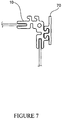
- FIG. 7 is a front view of the corner of an enclosure assembly including an interlocking structure for external mounting of assemblies.
- the present invention comprises a structural element which can be used to fabricate cabinets and enclosures with one or more compartments.
- the element is an elongated member with at least two surfaces and means for interlocking two elements together.
- Such means are typically comprised of elongated protrusions on the outer surfaces of each flange, shaped and positioned for proper interlocking.
- FIG. 1 The preferred embodiment of a structural element in accordance with the invention is shown in FIG. 1 .
- the structural element 10 is used in the corner of the compartment or cabinet and accordingly has a top flange 11 and a side flange 12 which are at approximately a right angle to each other.
- Each flange incorporates two slots 13 14 for a total of four slots.
- One slot 13 is parallel to the plane of the flange.
- the second slot 14 is perpendicular to the plane of the flange.
- the parallel slots are used to fix the side panels of the enclosure, while the perpendicular slots are used to mount a shelf within the enclosure.
- the preferred embodiment of the invention includes v-grooves 15 16 in the top and bottom surfaces of each flange.
- the v-grooves 15 16 are used to locate holes 17 18 for fixing the outer wall of the enclosure to the structural element.
- the preferred embodiment also includes a hole 25 near the vertex of the angle between the top and side flanges 11 12 . This hole 25 extends the length of the element and may be used to fix the front and back panels onto the enclosure.
- outward extending protrusions 19 20 21 22 are located on the outer surface of each flange.
- the protrusions have a generally hook shaped cross section with a head 23 and a neck 24 . All four protrusions 19 20 21 22 are identical in shape, but they are located in different positions along the width of the flanges.
- the cross section of the structural element is substantially uniform along the length of the element.
- the uniformity of the cross section is such that the preferred embodiment of the structural element may be suitably manufactured using an extrusion process.
- Each flange forming the right angle cross section has equal width, designated as dimension A.
- Each flange 11 12 includes a slot 13 13 ′ parallel to the plane of the flange, extending inward toward the vertex of the right angle. While the width and depth of the slot may vary considerably, dimensions should be chosen that permit fixing of the side panels of the enclosure without unduly compromising the structural strength of the member.
- the two flanges 11 12 also include a slot 14 14 ′ perpendicular to the plane of the flange. These slots are useful for mounting shelves, circuit boards, or other objects in the final enclosure. Additionally, a hole 25 is located near the vertex of the right angle between the flanges. Preferably, the diameter of the hole should be chosen so that it can be threaded and used to secure the front and back panels onto the enclosure with suitably sized screws. Alternately, rivets or other fastening means may be used.
- each protrusion 19 20 21 22 On the outer surface of each flange of the preferred embodiment of the structural element are located protrusions 19 20 21 22 to provide means for interlocking two identical structural elements together. All four protrusions in the preferred embodiment are identical in cross section, but vary in orientation and position relative to the vertex and edge of each flange.
- the pair of protrusions on the top flange has the same spacing relative to each other as the pair of protrusions on the side flange, denoted as dimension D.
- each protrusion is generally hook shaped, with a head 23 and a neck 24 .
- the heads of the protrusions on the top flange point toward the vertex of the right angle between the flanges, while the heads of the protrusions on the side flange point away from the vertex of the right angle between the flanges.
- the width of the necks of each protrusion is denoted as dimension X, and the height as dimension Y.
- Dimensions L 1 and L 2 indicate the position of the protrusions relative to the outer surface of the flanges 30 31 .
- FIG. 3 shows a closer view of the cross section of the interlocking protrusions 19 20 .
- the exact dimensions of the protrusions are chosen such that the space between the protrusions is slightly larger than a single protrusion and comparably shaped.
- the surface on one side of the each protrusion 40 is approximately flat, while the other side is formed from two semi-circular surfaces with radii R 1 and R 2 .
- R 2 is chosen to be slightly larger than R 1 . While the exact difference may vary considerably, R 2 is normally about 1% to 5% greater than R 1 . If the difference between the radii is too large, the interlocked elements will have too much freedom of motion. If the difference is too small, it may be difficult to slide two interlocking pieces together, especially if the pieces are long.
- the centers of the two radii, R 1 and R 2 are aligned in the vertical direction.
- the height of the protrusion, Y is approximately twice the sum of the two radii, R 1 and R 2 .
- FIG. 4 shows an end view of two identical structural elements 10 10 ′ interlocked in accordance with the invention.
- the protrusions on the top flange of a -first element interlock with the protrusions on the side flange of the second element.
- the interlocking is achieved by placing the elements end to end and sliding the second element into position relative to the first element.
- FIG. 5 shows an enclosure using structural elements in accordance with the preferred embodiment.
- Four identical elements 50 51 52 53 are placed at each corner of the enclosure and joined by four flat panels 54 55 56 57 .
- the panels may be made from any rigid material such as sheet metal or fiberglass. They are fixed to the structural elements with screws or other suitable means.
- a shelf 58 may be slid into slots in the structural elements.
- a front and back panel are affixed to the structural elements using the holes 25 near the corner of the structural elements and suitable fixing means such as screws or rivets.
- FIG. 6 shows a front view of an enclosure with four compartments in accordance with the invention.
- the enclosure of FIG. 6 is comprised of four smaller enclosures interlocked to each other.
- a single front and back panel can be used to complete the enclosure. This arrangement may be particularly useful if the enclosure is used to house electrical circuitry wherein it is desirable to shield each compartment from the others; or in situations where it is desirable to thermally isolate one compartment from another.
- the interlocking means provided in the structural element are not limited to interlocking with identical structural elements.
- a flat plate with interlocking means on one side may be used to mount components external to the enclosure.
- FIG. 7 shows such a mounting plate 70 interlocked with a structural element 10 in a cutaway view of one corner of an enclosure.
- the interlocking protrusions on the mounting plate have the same shape as those on the structural element, but may be positioned in any desirable location on the mounting plate.
Landscapes
- Assembled Shelves (AREA)
Abstract
Description
- U.S. Pat. No. 2,167,525: Rosendale
- U.S. Pat. No. 5,066,161: Pinney
- U.S. Pat. No. 3,265,419: Durnbaugh, et al.
- U.S. Pat. No. 3,182,846: La Kaff
- U.S. Pat. No. 3,919,603: Salvati
Claims (8)
Priority Applications (3)
| Application Number | Priority Date | Filing Date | Title |
|---|---|---|---|
| US11/807,037 US7922417B2 (en) | 2007-05-25 | 2007-05-25 | Interlocking structural element for cabinets and enclosures |
| PCT/US2008/006668 WO2008153780A1 (en) | 2007-05-25 | 2008-05-23 | Interlockings structural element for cabinets and enclosures |
| US13/042,951 US20110163648A1 (en) | 2007-05-25 | 2011-03-08 | Interlocking Structural Element for Cabinets and Enclosures |
Applications Claiming Priority (1)
| Application Number | Priority Date | Filing Date | Title |
|---|---|---|---|
| US11/807,037 US7922417B2 (en) | 2007-05-25 | 2007-05-25 | Interlocking structural element for cabinets and enclosures |
Related Child Applications (1)
| Application Number | Title | Priority Date | Filing Date |
|---|---|---|---|
| US13/042,951 Continuation US20110163648A1 (en) | 2007-05-25 | 2011-03-08 | Interlocking Structural Element for Cabinets and Enclosures |
Publications (2)
| Publication Number | Publication Date |
|---|---|
| US20080290771A1 US20080290771A1 (en) | 2008-11-27 |
| US7922417B2 true US7922417B2 (en) | 2011-04-12 |
Family
ID=40071754
Family Applications (2)
| Application Number | Title | Priority Date | Filing Date |
|---|---|---|---|
| US11/807,037 Expired - Fee Related US7922417B2 (en) | 2007-05-25 | 2007-05-25 | Interlocking structural element for cabinets and enclosures |
| US13/042,951 Abandoned US20110163648A1 (en) | 2007-05-25 | 2011-03-08 | Interlocking Structural Element for Cabinets and Enclosures |
Family Applications After (1)
| Application Number | Title | Priority Date | Filing Date |
|---|---|---|---|
| US13/042,951 Abandoned US20110163648A1 (en) | 2007-05-25 | 2011-03-08 | Interlocking Structural Element for Cabinets and Enclosures |
Country Status (2)
| Country | Link |
|---|---|
| US (2) | US7922417B2 (en) |
| WO (1) | WO2008153780A1 (en) |
Cited By (32)
| Publication number | Priority date | Publication date | Assignee | Title |
|---|---|---|---|---|
| US20120028534A1 (en) * | 2010-07-30 | 2012-02-02 | Dennis Clifford Unger | Structural support fastener |
| US8514577B2 (en) * | 2011-02-15 | 2013-08-20 | Vivotek Inc. | Video server set |
| USD689024S1 (en) | 2011-12-09 | 2013-09-03 | Trystar, Inc. | Portable power distribution box |
| US8616661B2 (en) | 2011-12-09 | 2013-12-31 | Trystar, Inc. | Portable power distribution box |
| US20150072587A1 (en) * | 2013-09-10 | 2015-03-12 | Noah J. Ornstein | Magnetic Building Tiles |
| US20150289388A1 (en) * | 2014-04-04 | 2015-10-08 | Tyco Electronics Corporation | Modular Enclosure |
| USD743908S1 (en) | 2014-12-03 | 2015-11-24 | Trystar, Inc. | Portable power distribution box |
| US9347213B1 (en) | 2014-11-14 | 2016-05-24 | Cooper Technologies Company | Fitting for channel framing |
| US9382038B2 (en) | 2014-04-04 | 2016-07-05 | Tyco Electronics Corporation | Modular enclosure |
| US9453592B2 (en) | 2013-03-14 | 2016-09-27 | Cooper Technologies Company | Fitting including clip for channel framing |
| US9458952B2 (en) | 2014-04-30 | 2016-10-04 | Cooper Technologies Company | Trapeze hanger system including twist-locking fitting |
| US9546744B2 (en) | 2014-05-02 | 2017-01-17 | Cooper Technologies Company | Conduit clamp for strut channel |
| US9574589B2 (en) | 2014-04-30 | 2017-02-21 | Cooper Technologies Company | Trapeze hanger system including trapeze hanger fitting |
| US9683590B2 (en) | 2014-05-02 | 2017-06-20 | Cooper Technologies Company | Strut system and strut fitting therefor |
| US9790980B2 (en) | 2013-12-23 | 2017-10-17 | Cooper Technologies Company | Fastener nut for channel framing |
| US9926957B2 (en) | 2014-11-14 | 2018-03-27 | Cooper Technologies Company | Fitting for strut channel |
| US9982695B2 (en) | 2014-11-14 | 2018-05-29 | Cooper Technologies Company | Fitting for strut channel |
| US10018224B2 (en) * | 2016-07-21 | 2018-07-10 | Edward Korn | Machine structural member with nesting linear slides |
| US10100861B2 (en) | 2014-11-14 | 2018-10-16 | Cooper Technologies Company | Beam clamp for strut channel |
| USD832366S1 (en) | 2017-06-29 | 2018-10-30 | Box Tiles Llc | Toy connector |
| US10143298B2 (en) | 2016-04-07 | 2018-12-04 | Douglas Wood | Modular structural support apparatus and method of constructing the same |
| US10258896B2 (en) | 2013-09-10 | 2019-04-16 | Box Tiles Llc | Magnetic building tiles |
| US10288115B2 (en) * | 2017-01-28 | 2019-05-14 | Edward Korn | Machine structural member with nesting linear slides |
| USD867263S1 (en) | 2017-06-29 | 2019-11-19 | Box Tiles Llc | Toy building frame |
| USD868170S1 (en) | 2017-06-29 | 2019-11-26 | Box Tiles Llc | Toy bridge clip |
| USD868169S1 (en) | 2017-06-29 | 2019-11-26 | Box Tiles Llc | Toy building panel |
| US10544580B2 (en) * | 2014-12-15 | 2020-01-28 | Certainteed Corporation | System, method and apparatus for corner siding |
| US10548232B2 (en) | 2017-10-02 | 2020-01-28 | Te Connectivity Corporation | Modular enclosure and an assembly for constructing a modular enclosure |
| USD884802S1 (en) | 2017-06-29 | 2020-05-19 | Box Tiles Llc | Toy building panel |
| US12025176B2 (en) | 2021-03-17 | 2024-07-02 | Steelcase Inc. | Clip fastener for privacy screen |
| US20240279945A1 (en) * | 2023-02-16 | 2024-08-22 | Aluvision N.V. | Exhibition stand |
| US12573824B2 (en) | 2022-10-17 | 2026-03-10 | Trystar, Llc | Electrical distribution box |
Families Citing this family (7)
| Publication number | Priority date | Publication date | Assignee | Title |
|---|---|---|---|---|
| US7866769B2 (en) | 2006-09-06 | 2011-01-11 | Target Brands, Inc. | Storage and organization system and components thereof |
| EP2087496A1 (en) * | 2006-10-31 | 2009-08-12 | Linak A/S | A motor operator for switchgear for mains power distribution systems |
| DK2080206T3 (en) * | 2006-10-31 | 2012-02-13 | Linak As | An engine unit for switchgear for power supply systems |
| US8186776B2 (en) * | 2009-03-17 | 2012-05-29 | Target Brands, Inc. | Storage and organization system and connectivity of the components therein |
| USD682218S1 (en) | 2011-12-09 | 2013-05-14 | Trystar, Inc. | Portable power distribution box |
| US10407769B2 (en) * | 2016-03-18 | 2019-09-10 | Goodrich Corporation | Method and apparatus for decreasing the radial temperature gradient in CVI/CVD furnaces |
| DE202021104596U1 (en) | 2021-08-26 | 2022-11-29 | Weidmüller Interface GmbH & Co. KG | housing system |
Citations (26)
| Publication number | Priority date | Publication date | Assignee | Title |
|---|---|---|---|---|
| US2167525A (en) | 1935-08-08 | 1939-07-25 | Western Electric Co | Cabinet |
| US3044658A (en) * | 1958-05-12 | 1962-07-17 | Zero Mfg Company | Shipping container |
| US3182846A (en) | 1961-04-11 | 1965-05-11 | Borg Warner | Cabinet structure |
| US3265419A (en) | 1963-12-30 | 1966-08-09 | Honeywell Inc | Cabinet structure |
| US3751127A (en) * | 1970-09-10 | 1973-08-07 | Telecommunication Technology I | Modular instrument housing |
| US3919603A (en) | 1973-02-21 | 1975-11-11 | Westinghouse Electric Corp | Switchboard framework corner tie |
| US4123129A (en) * | 1976-11-18 | 1978-10-31 | Tektronix, Inc. | Modular electronic instrument cabinets |
| US4470647A (en) * | 1982-06-01 | 1984-09-11 | Mark L. Bishoff | Interfitting and removable modular storage units including connectors forming part of a unit as well as sliding support for adjacent units |
| US4585131A (en) * | 1983-12-19 | 1986-04-29 | Amstore Corporation | Variable decor merchandising system |
| US4621938A (en) * | 1984-04-17 | 1986-11-11 | Hennix I Stockholm Ab | Joint |
| US5039177A (en) * | 1990-07-02 | 1991-08-13 | Haworth, Inc. | Cabinet with panel-attachment corner detail |
| US5066161A (en) | 1989-05-08 | 1991-11-19 | Pinney Richard C | Framework for cabinet structure |
| US5429438A (en) | 1993-07-12 | 1995-07-04 | 80/20 Inc. | Mechanical structure and guide block |
| USD362509S (en) * | 1993-07-05 | 1995-09-19 | AAF-Ltd. | Framework connector |
| US5470139A (en) * | 1994-01-24 | 1995-11-28 | Hsiao; Szu-Chang | Combined display case |
| US5695263A (en) * | 1993-02-25 | 1997-12-09 | Knurr-Mechanik Fur Die Elektronik Aktiengesellschaft | Cabinet |
| US5746333A (en) * | 1996-03-05 | 1998-05-05 | Contract Industrial Tooling, Inc. | Rigid storage device with variable sized cells |
| US5888114A (en) * | 1996-02-16 | 1999-03-30 | Aesop, Inc. | Modular storage system, components, accessories, and applications to structural systems and toy construction sets and the like |
| USD412585S (en) * | 1998-01-29 | 1999-08-03 | Champion Aluminum Corporation | Frame element extrusion |
| US6030063A (en) * | 1994-12-23 | 2000-02-29 | Rittal-Werk Rudolf Loh Gmbh & Co. Kg | Switchgear cabinet with frame |
| US6082837A (en) * | 1996-11-27 | 2000-07-04 | Alu, Inc. | Modular display system of interlocking components |
| US6120116A (en) * | 1998-08-10 | 2000-09-19 | Buckeye Stamping Company, Inc. | Circuit board storage cabinet |
| US6223917B1 (en) * | 1998-10-16 | 2001-05-01 | Octanorm-Vertriebs-Gmbh Fuer Bauelemente | Profile arrangement for building exhibition or shop systems |
| US6802171B2 (en) * | 2002-10-18 | 2004-10-12 | Mckinnon Duane | Framing member with fastener attachments having square threads |
| US6837389B2 (en) * | 2001-11-15 | 2005-01-04 | DOMO Architektursystems Logistic GmbH | Profile-section support system for industrial-fair and exhibition construction |
| US20050129460A1 (en) * | 2003-12-11 | 2005-06-16 | Excell Products, Inc. | Modular frame corners |
Family Cites Families (2)
| Publication number | Priority date | Publication date | Assignee | Title |
|---|---|---|---|---|
| US5142445A (en) * | 1990-06-01 | 1992-08-25 | Sorensen Bradford T | Modular stackable interlocking storage cabinet for electronic components |
| IT1314303B1 (en) * | 1999-12-21 | 2002-12-09 | Abb Ricerca Spa | ELEMENT FOR FRAMEWORK OF A CABINET FOR ELECTRICAL PANEL |
-
2007
- 2007-05-25 US US11/807,037 patent/US7922417B2/en not_active Expired - Fee Related
-
2008
- 2008-05-23 WO PCT/US2008/006668 patent/WO2008153780A1/en not_active Ceased
-
2011
- 2011-03-08 US US13/042,951 patent/US20110163648A1/en not_active Abandoned
Patent Citations (26)
| Publication number | Priority date | Publication date | Assignee | Title |
|---|---|---|---|---|
| US2167525A (en) | 1935-08-08 | 1939-07-25 | Western Electric Co | Cabinet |
| US3044658A (en) * | 1958-05-12 | 1962-07-17 | Zero Mfg Company | Shipping container |
| US3182846A (en) | 1961-04-11 | 1965-05-11 | Borg Warner | Cabinet structure |
| US3265419A (en) | 1963-12-30 | 1966-08-09 | Honeywell Inc | Cabinet structure |
| US3751127A (en) * | 1970-09-10 | 1973-08-07 | Telecommunication Technology I | Modular instrument housing |
| US3919603A (en) | 1973-02-21 | 1975-11-11 | Westinghouse Electric Corp | Switchboard framework corner tie |
| US4123129A (en) * | 1976-11-18 | 1978-10-31 | Tektronix, Inc. | Modular electronic instrument cabinets |
| US4470647A (en) * | 1982-06-01 | 1984-09-11 | Mark L. Bishoff | Interfitting and removable modular storage units including connectors forming part of a unit as well as sliding support for adjacent units |
| US4585131A (en) * | 1983-12-19 | 1986-04-29 | Amstore Corporation | Variable decor merchandising system |
| US4621938A (en) * | 1984-04-17 | 1986-11-11 | Hennix I Stockholm Ab | Joint |
| US5066161A (en) | 1989-05-08 | 1991-11-19 | Pinney Richard C | Framework for cabinet structure |
| US5039177A (en) * | 1990-07-02 | 1991-08-13 | Haworth, Inc. | Cabinet with panel-attachment corner detail |
| US5695263A (en) * | 1993-02-25 | 1997-12-09 | Knurr-Mechanik Fur Die Elektronik Aktiengesellschaft | Cabinet |
| USD362509S (en) * | 1993-07-05 | 1995-09-19 | AAF-Ltd. | Framework connector |
| US5429438A (en) | 1993-07-12 | 1995-07-04 | 80/20 Inc. | Mechanical structure and guide block |
| US5470139A (en) * | 1994-01-24 | 1995-11-28 | Hsiao; Szu-Chang | Combined display case |
| US6030063A (en) * | 1994-12-23 | 2000-02-29 | Rittal-Werk Rudolf Loh Gmbh & Co. Kg | Switchgear cabinet with frame |
| US5888114A (en) * | 1996-02-16 | 1999-03-30 | Aesop, Inc. | Modular storage system, components, accessories, and applications to structural systems and toy construction sets and the like |
| US5746333A (en) * | 1996-03-05 | 1998-05-05 | Contract Industrial Tooling, Inc. | Rigid storage device with variable sized cells |
| US6082837A (en) * | 1996-11-27 | 2000-07-04 | Alu, Inc. | Modular display system of interlocking components |
| USD412585S (en) * | 1998-01-29 | 1999-08-03 | Champion Aluminum Corporation | Frame element extrusion |
| US6120116A (en) * | 1998-08-10 | 2000-09-19 | Buckeye Stamping Company, Inc. | Circuit board storage cabinet |
| US6223917B1 (en) * | 1998-10-16 | 2001-05-01 | Octanorm-Vertriebs-Gmbh Fuer Bauelemente | Profile arrangement for building exhibition or shop systems |
| US6837389B2 (en) * | 2001-11-15 | 2005-01-04 | DOMO Architektursystems Logistic GmbH | Profile-section support system for industrial-fair and exhibition construction |
| US6802171B2 (en) * | 2002-10-18 | 2004-10-12 | Mckinnon Duane | Framing member with fastener attachments having square threads |
| US20050129460A1 (en) * | 2003-12-11 | 2005-06-16 | Excell Products, Inc. | Modular frame corners |
Cited By (48)
| Publication number | Priority date | Publication date | Assignee | Title |
|---|---|---|---|---|
| US20120028534A1 (en) * | 2010-07-30 | 2012-02-02 | Dennis Clifford Unger | Structural support fastener |
| US8514577B2 (en) * | 2011-02-15 | 2013-08-20 | Vivotek Inc. | Video server set |
| USD689024S1 (en) | 2011-12-09 | 2013-09-03 | Trystar, Inc. | Portable power distribution box |
| US8616661B2 (en) | 2011-12-09 | 2013-12-31 | Trystar, Inc. | Portable power distribution box |
| US10619791B2 (en) | 2013-03-14 | 2020-04-14 | Eaton Intelligent Power Limited | Channel framing with additional functional side |
| US9453592B2 (en) | 2013-03-14 | 2016-09-27 | Cooper Technologies Company | Fitting including clip for channel framing |
| US9651171B2 (en) | 2013-03-14 | 2017-05-16 | Cooper Technologies Company | Nut-washer assembly for channel framing |
| US9587767B2 (en) | 2013-03-14 | 2017-03-07 | Cooper Technology Company | Fitting for trapeze hanger |
| US9746105B2 (en) | 2013-03-14 | 2017-08-29 | Cooper Technologies Company | Conduit clamp for channel framing |
| US9982837B2 (en) | 2013-03-14 | 2018-05-29 | Cooper Technologies Company | Fitting including clip for channel framing |
| US9470339B2 (en) | 2013-03-14 | 2016-10-18 | Cooper Technologies Company | Fitting for connecting two pieces of channel framing to one another |
| US20150072587A1 (en) * | 2013-09-10 | 2015-03-12 | Noah J. Ornstein | Magnetic Building Tiles |
| US10258896B2 (en) | 2013-09-10 | 2019-04-16 | Box Tiles Llc | Magnetic building tiles |
| US9314707B2 (en) * | 2013-09-10 | 2016-04-19 | Box Tiles Llc | Magnetic building tiles |
| US10918963B2 (en) | 2013-09-10 | 2021-02-16 | Squaregles Llc | Magnetic building tiles |
| US9790980B2 (en) | 2013-12-23 | 2017-10-17 | Cooper Technologies Company | Fastener nut for channel framing |
| US20150289388A1 (en) * | 2014-04-04 | 2015-10-08 | Tyco Electronics Corporation | Modular Enclosure |
| US9392708B2 (en) * | 2014-04-04 | 2016-07-12 | Tyco Electronics Corporation | Modular enclosure |
| US9382038B2 (en) | 2014-04-04 | 2016-07-05 | Tyco Electronics Corporation | Modular enclosure |
| US9458952B2 (en) | 2014-04-30 | 2016-10-04 | Cooper Technologies Company | Trapeze hanger system including twist-locking fitting |
| US9732887B2 (en) | 2014-04-30 | 2017-08-15 | Cooper Technologies Company | Trapeze hanger system including twist-locking fitting |
| US9574589B2 (en) | 2014-04-30 | 2017-02-21 | Cooper Technologies Company | Trapeze hanger system including trapeze hanger fitting |
| US10012255B2 (en) | 2014-04-30 | 2018-07-03 | Cooper Technologies Company | Trapeze hanger system including trapeze hanger fitting |
| US9989169B2 (en) | 2014-05-02 | 2018-06-05 | Cooper Technologies Company | Conduit clamp for strut channel |
| US9683590B2 (en) | 2014-05-02 | 2017-06-20 | Cooper Technologies Company | Strut system and strut fitting therefor |
| US9546744B2 (en) | 2014-05-02 | 2017-01-17 | Cooper Technologies Company | Conduit clamp for strut channel |
| US10161127B2 (en) | 2014-11-14 | 2018-12-25 | Cooper Technologies Company | Fitting for channel framing |
| US9982695B2 (en) | 2014-11-14 | 2018-05-29 | Cooper Technologies Company | Fitting for strut channel |
| US10100861B2 (en) | 2014-11-14 | 2018-10-16 | Cooper Technologies Company | Beam clamp for strut channel |
| US9926957B2 (en) | 2014-11-14 | 2018-03-27 | Cooper Technologies Company | Fitting for strut channel |
| US9580900B2 (en) | 2014-11-14 | 2017-02-28 | Cooper Technologies Company | Fitting for channel framing |
| US9347213B1 (en) | 2014-11-14 | 2016-05-24 | Cooper Technologies Company | Fitting for channel framing |
| USD743908S1 (en) | 2014-12-03 | 2015-11-24 | Trystar, Inc. | Portable power distribution box |
| US10544580B2 (en) * | 2014-12-15 | 2020-01-28 | Certainteed Corporation | System, method and apparatus for corner siding |
| US10745909B2 (en) * | 2014-12-15 | 2020-08-18 | Certainteed Corporation | System, method, and apparatus for corner siding |
| US10143298B2 (en) | 2016-04-07 | 2018-12-04 | Douglas Wood | Modular structural support apparatus and method of constructing the same |
| US10018224B2 (en) * | 2016-07-21 | 2018-07-10 | Edward Korn | Machine structural member with nesting linear slides |
| US10288115B2 (en) * | 2017-01-28 | 2019-05-14 | Edward Korn | Machine structural member with nesting linear slides |
| USD868169S1 (en) | 2017-06-29 | 2019-11-26 | Box Tiles Llc | Toy building panel |
| USD868170S1 (en) | 2017-06-29 | 2019-11-26 | Box Tiles Llc | Toy bridge clip |
| USD884802S1 (en) | 2017-06-29 | 2020-05-19 | Box Tiles Llc | Toy building panel |
| USD867263S1 (en) | 2017-06-29 | 2019-11-19 | Box Tiles Llc | Toy building frame |
| USD900246S1 (en) | 2017-06-29 | 2020-10-27 | Squaregles Llc | Toy building panel |
| USD832366S1 (en) | 2017-06-29 | 2018-10-30 | Box Tiles Llc | Toy connector |
| US10548232B2 (en) | 2017-10-02 | 2020-01-28 | Te Connectivity Corporation | Modular enclosure and an assembly for constructing a modular enclosure |
| US12025176B2 (en) | 2021-03-17 | 2024-07-02 | Steelcase Inc. | Clip fastener for privacy screen |
| US12573824B2 (en) | 2022-10-17 | 2026-03-10 | Trystar, Llc | Electrical distribution box |
| US20240279945A1 (en) * | 2023-02-16 | 2024-08-22 | Aluvision N.V. | Exhibition stand |
Also Published As
| Publication number | Publication date |
|---|---|
| WO2008153780A1 (en) | 2008-12-18 |
| US20080290771A1 (en) | 2008-11-27 |
| US20110163648A1 (en) | 2011-07-07 |
Similar Documents
| Publication | Publication Date | Title |
|---|---|---|
| US7922417B2 (en) | Interlocking structural element for cabinets and enclosures | |
| US5066161A (en) | Framework for cabinet structure | |
| JP2895239B2 (en) | Frame used for switch cabinet | |
| US3751127A (en) | Modular instrument housing | |
| US5997117A (en) | Rack frame cabinet | |
| US6974036B2 (en) | Corner post and manufacturing process for making same | |
| US10143298B2 (en) | Modular structural support apparatus and method of constructing the same | |
| US6036290A (en) | Seismic subframe for electrical enclosure | |
| US6962262B2 (en) | Connecting corner for knock down racks | |
| EP0472793A1 (en) | Framework for cabinet structure | |
| US5014861A (en) | Modular system for setting up furniture, racks, frameworks and the like | |
| US4172623A (en) | Picture frame cabinet | |
| WO2022001711A1 (en) | Display screen | |
| US20120183827A1 (en) | Riveted module | |
| US9795230B2 (en) | Modular display unit | |
| US10610013B2 (en) | Modular cabinet design | |
| JP2018051266A (en) | Storage shelf and storage shelf set | |
| JP5670236B2 (en) | Cabinet connection structure | |
| CN2164727Y (en) | Assembled table and cabinet | |
| CN216870673U (en) | Portable microwave test camera bellows | |
| KR101708110B1 (en) | Panel Assembly And Furniture Made Of The Same | |
| JPS642147Y2 (en) | ||
| US11696640B2 (en) | Shelving system | |
| JPH0143739Y2 (en) | ||
| JPS5825871Y2 (en) | Combined flat shelf |
Legal Events
| Date | Code | Title | Description |
|---|---|---|---|
| REMI | Maintenance fee reminder mailed | ||
| LAPS | Lapse for failure to pay maintenance fees | ||
| REIN | Reinstatement after maintenance fee payment confirmed | ||
| FP | Lapsed due to failure to pay maintenance fee |
Effective date: 20150412 |
|
| FEPP | Fee payment procedure |
Free format text: PETITION RELATED TO MAINTENANCE FEES FILED (ORIGINAL EVENT CODE: PMFP); ENTITY STATUS OF PATENT OWNER: SMALL ENTITY |
|
| FEPP | Fee payment procedure |
Free format text: PETITION RELATED TO MAINTENANCE FEES GRANTED (ORIGINAL EVENT CODE: PMFG); ENTITY STATUS OF PATENT OWNER: SMALL ENTITY |
|
| FPAY | Fee payment |
Year of fee payment: 4 |
|
| SULP | Surcharge for late payment | ||
| PRDP | Patent reinstated due to the acceptance of a late maintenance fee |
Effective date: 20160608 |
|
| STCF | Information on status: patent grant |
Free format text: PATENTED CASE |
|
| FEPP | Fee payment procedure |
Free format text: MAINTENANCE FEE REMINDER MAILED (ORIGINAL EVENT CODE: REM.); ENTITY STATUS OF PATENT OWNER: SMALL ENTITY |
|
| LAPS | Lapse for failure to pay maintenance fees |
Free format text: PATENT EXPIRED FOR FAILURE TO PAY MAINTENANCE FEES (ORIGINAL EVENT CODE: EXP.); ENTITY STATUS OF PATENT OWNER: SMALL ENTITY |
|
| STCH | Information on status: patent discontinuation |
Free format text: PATENT EXPIRED DUE TO NONPAYMENT OF MAINTENANCE FEES UNDER 37 CFR 1.362 |
|
| FP | Lapsed due to failure to pay maintenance fee |
Effective date: 20190412 |