US7917236B1 - Virtual sound source device and acoustic device comprising the same - Google Patents
Virtual sound source device and acoustic device comprising the same Download PDFInfo
- Publication number
- US7917236B1 US7917236B1 US09/647,444 US64744400A US7917236B1 US 7917236 B1 US7917236 B1 US 7917236B1 US 64744400 A US64744400 A US 64744400A US 7917236 B1 US7917236 B1 US 7917236B1
- Authority
- US
- United States
- Prior art keywords
- listener
- sound source
- virtual sound
- signal
- response
- Prior art date
- Legal status (The legal status is an assumption and is not a legal conclusion. Google has not performed a legal analysis and makes no representation as to the accuracy of the status listed.)
- Expired - Fee Related
Links
Images


Classifications
-
- H—ELECTRICITY
- H04—ELECTRIC COMMUNICATION TECHNIQUE
- H04S—STEREOPHONIC SYSTEMS
- H04S1/00—Two-channel systems
-
- H—ELECTRICITY
- H04—ELECTRIC COMMUNICATION TECHNIQUE
- H04S—STEREOPHONIC SYSTEMS
- H04S1/00—Two-channel systems
- H04S1/007—Two-channel systems in which the audio signals are in digital form
-
- G—PHYSICS
- G10—MUSICAL INSTRUMENTS; ACOUSTICS
- G10K—SOUND-PRODUCING DEVICES; METHODS OR DEVICES FOR PROTECTING AGAINST, OR FOR DAMPING, NOISE OR OTHER ACOUSTIC WAVES IN GENERAL; ACOUSTICS NOT OTHERWISE PROVIDED FOR
- G10K15/00—Acoustics not otherwise provided for
- G10K15/02—Synthesis of acoustic waves
-
- H—ELECTRICITY
- H04—ELECTRIC COMMUNICATION TECHNIQUE
- H04S—STEREOPHONIC SYSTEMS
- H04S7/00—Indicating arrangements; Control arrangements, e.g. balance control
- H04S7/30—Control circuits for electronic adaptation of the sound field
- H04S7/302—Electronic adaptation of stereophonic sound system to listener position or orientation
- H04S7/303—Tracking of listener position or orientation
- H04S7/304—For headphones
Definitions
- This invention relates to a virtual sound source device for generating virtual sound source and a sound apparatus and a sound equipment using such a virtual sound source device, and more particularly to a virtual sound source reproducing device comprising first signal processing means for carrying out signal processing in accordance with an impulse response portion which can perceive or sense position of virtual sound source of impulse responses of transfer functions of audio signals from the virtual sound source until to ears, second signal processing means for carrying out signal processing in accordance with impulse response portion which can perceive or sense only distance of the virtual sound source, and response characteristic control means for detecting change or movement of positions of both ears to control and correct response characteristic of the first signal processing means, and a sound apparatus and a sound equipment using such a virtual sound source device.
- audio signals of plural channels are used as the sound source followed by image of cinema, etc.
- Such audio signal channels of plural channels are recorded on the assumption that they are respectively delivered to speakers disposed at both sides and the center of screen onto which image is projected and speakers disposed at the rear side or both lateral sides of listener, etc. so that they are reproduced.
- audio signals of plural channels by reproducing audio signals of plural channels by three-dimensionally disposed speakers, sound position followed by image and position of sound image actually heard can be in correspondence with each other.
- sound field having natural spreading of sound can be established.
- headphone devices of the stereo out-of-head sound image localization type adapted to measure or calculate transfer functions or impulse responses from speakers provided so as to respectively reproduce audio signals of respective channels in advance until both ears of listener to convolute them onto audio signals from sound source by digital filter, etc. thereafter to listen to it by headphone device to thereby position (localize) sound image outside the head.
- This headphone device 8 localizes reproduction sound image by audio signal to the left ear and audio signal to the right ear at the outside of the head.
- Audio signals are transmitted to left ear YL and right ear YR of listener M from sound source SL of the left side through paths having transfer functions of HLL, HLR, respectively.
- audio signals are transmitted to the left ear YL and the right year YR of listener from sound source SR of the right side through paths having transfer functions of HRL, HRR, respectively.
- audio signal Sal from sound source SL of the left side is caused to be through filter for realizing transfer function HLL so that audio signal Sbll for left ear is obtained and audio signal Sal is caused to be through filter for realizing transfer function HLR so that audio signal for right ear is obtained.
- audio signal Sar of sound source SR of the right side is caused to be through filter for realizing transfer function HRL so that audio signal Sbrl for left ear is obtained and audio signal Sar is caused to be through filter for realizing transfer function HRR so that audio signal Sbrr for right ear is obtained.
- Such an approach is employed to drive left and right headphone elements 6 a , 6 b of headphone 6 by these left and right synthetic audio signals Sbll, Sblr.
- listener can perceive or sense sound image as if sound source is disposed at sound sources SL and SR.
- This headphone device 8 comprises a first input terminal 1 L supplied with audio signal Sal, a second input terminal 1 R supplied with audio signal Sar, a second input terminal 1 R supplied with audio signal Sar, A/D converters 2 L, 2 R for respectively converting respective audio signals Sal, Sar into corresponding digital signals, signal processing circuits 3 L, 3 R for implementing filtering (processing) to the respective audio signals Sal, Sar converted into digital signals, adders 7 L, 7 R for adding outputs of respective two systems, D/A converters 4 L, 4 R for converting added outputs of 2 systems into analog signals, and amplifiers 5 L, 5 R for amplifying analog audio signals outputted from the respective D/A converters 4 L, 4 R to supply them to left and right headphone elements 6 a , 6 b of the headphone 6 .
- one signal processing circuit 3 L is constituted by two digital filters 10 , 11 as shown in FIG. 3 , wherein one digital filter 10 carries out convolution of impulse response of transfer function HLL with respect to audio signal Sal inputted through an input terminal 12 to form a left ear audio signal Sbll to output it from an output terminal 13 , and the other digital filter 11 carries out convolution of impulse response of transfer function HLR with respect to audio signal Sal inputted through the input terminal 12 to form a right ear audio signal Sblr to output it from an output terminal 14 .
- the other signal processing circuit 3 R is similarly constituted by two digital filters 10 , 11 as shown in FIG. 3 , wherein one digital filter 10 carries out convolution of impulse response for realizing transfer function HRL with respect to an audio signal Sar inputted through the input terminal 12 to form a left ear audio signal Sbrl to output it from the output terminal 13 , and the other digital filter 11 carries out convolution of impulse response for realizing transfer function HRR with respect to an audio signal Sar inputted through the input terminal 12 to form a right ear audio signal Sbrr to output it from the output terminal 14 .
- the above-mentioned impulse response has characteristic as shown in FIG. 4 .
- the respective digital filters 10 , 11 are constituted by FIR type digital filter 15 as shown in FIG. 5 , for example.
- This FIR type digital filter 15 comprises, as shown in FIG. 5 , plural delay elements 16 cascade-connected having a predetermined delay quantity, plural coefficient multipliers 17 for multiplying inputted audio signal and audio signals delayed by respective delay elements 16 by coefficients for carrying out convolution of impulse response, and plural adders 18 for adding audio signals outputted from the respective coefficient multipliers 17 .
- the coefficient multipliers 17 of respective stages respectively multiply input audio signal Sal and audio signals delayed in sequence at delay elements 16 of respective stages by coefficients for carrying out convolution of impulse response to deliver them to adders 18 of corresponding stages.
- the adders 18 of respective stages add, to outputs of adders 18 of preceding stages, outputs of coefficient multipliers 17 of corresponding stages to deliver them to adders 18 of succeeding stages.
- the adder 18 of the final stage carries out convolution of impulse response of transfer function HLL (HLR) with respect to audio signal Sal (Sar) inputted through the input terminal 12 to form left ear audio signal Sbll (right ear audio signal Sblr) to output it through the output terminal 13 ( 14 ).
- HLL transfer function
- the adder 18 of the final stage of the digital filter 10 ( 11 ) in the signal processing circuit 3 R carries out convolution of impulse response of transfer function HRL (HRR) with respect to audio signal Sal (Sar) inputted through the input terminal 12 to form left ear audio signal Sbrl (right ear audio signal Sbrr) to output it through the output terminal 13 ( 14 ).
- HRL transfer function
- the FIR type digital filter 20 shown in FIG. 6 is constituted as a single filter block by sharing cascade-connected plural delay elements 16 in obtaining outputs of two systems by using two FIR type digital filters 15 shown in FIG. 5 .
- FIR type digital filter 20 is constituted as shown in FIG. 6 .
- the number of delay elements is reduced to one half so that the circuit scale becomes compact and signal processing operation quantity is reduced.
- left ear audio signals Sbll, Sbrl outputted from signal processing circuits 3 L, 3 R of the headphone device 8 shown in FIG. 1 are added by one adder 7 L so that left ear synthetic audio signal Sbl is obtained
- right ear audio signals Sblr, Sbrr outputted from signal processing circuits 3 L, 3 R are added by one adder 7 L so that right ear synthetic audio signal Sbr is obtained.
- the left ear synthetic audio signal Sbl and the right ear synthetic audio signal Sbr obtained in this way are respectively converted into analog signals at D/A converters 4 L, 4 R.
- the left ear synthetic audio signal Sbl and the right ear synthetic audio signal Sbr converted into analog signals are respectively amplified by amplifiers 5 L, 5 R.
- the signals thus amplified are respectively delivered to left and right headphone elements ba, 6 b of the headphone 6 so that they are reproduced.
- listener M who has attached the headphone 6 perceives (senses) as if left and right two sound sources SL, SR are actually exist as shown in FIG. 2 , thus making it possible to respectively localize reproduction sound images by the left ear synthetic audio signal Sbl and the right ear synthetic audio signal Sbr at the outside of the head.
- SL ⁇ ( HOL ⁇ HRR ⁇ HOR ⁇ HRL )/( HLL ⁇ HRR ⁇ HLR ⁇ HRL ) ⁇ SO (1)
- SR ⁇ ( HOR ⁇ HLL ⁇ HOL ⁇ HLR )/( HLL ⁇ HRR ⁇ HLR ⁇ HRL ) ⁇ SO (2)
- Speaker unit 30 for reproducing virtual sound source SO as described above can localize sound image of input signal inputted from two speakers to both ears at an ordinary position as shown in FIG. 7 .
- This speaker unit 30 comprises an input terminal 21 supplied with audio signal Sao, an A/D converter 22 for converting the audio signal Sao into digital signal, and a signal processing section (unit) 23 for implementing filtering (processing) to the audio signal Sao converted into digital signal.
- the signal processing unit 23 is constituted by the previously described two digital filters 10 , 11 as shown in FIG.
- one digital filter 10 convolutes impulse response corresponding to transfer function portion of the above-described formula (1) with respect to audio signal Sao to form left ear synthetic audio signal Sbl
- the other digital filter 11 convolutes impulse response corresponding to transfer function portion of the above-described formula (2) with respect to audio signal Sao to form right ear synthetic audio signal Sbr.
- digital filters 10 , 11 for realizing transfer function e.g., the previously described FIR type digital filter 15 shown in FIG. 5 or the previously described FIR type digital filter 20 shown in FIG. 6 is used, thereby making it possible to reduce the circuit scale.
- the left ear and right ear synthetic audio signals Sbl, Sbr are respectively converted into analog signals by D/A converters 24 L, 24 R, and the left and right ear synthetic audio signals Sbl, Sbr of analog signal are respectively amplified by amplifiers 25 L, 25 R and are delivered to a left speaker 26 L and a right speaker 26 R.
- the left and right speakers 26 L, 26 R are respectively disposed at positions of sound sources SL, SR with respect to listener M.
- reproduction sound image by audio signal Sao can be localized at position of virtual sound source SO. Further, with respect to a larger number of sound sources, it is sufficient to carry out the above-described processing by the number of sound sources. Since a larger number of virtual speaker sound sources can be constituted from a lesser number of speaker sound sources by this method, the number of speakers can be reduced.
- This invention has been proposed in view of circumstances described above, and its object is to provide a virtual sound source reproducing device, and a sound apparatus and a sound equipment using such a device, wherein, in a sound apparatus such as headphone unit or speaker unit, etc. and a sound equipment used in combination therewith, it is possible to localize sound image with sufficient feeling of distance at an arbitrary position while suppressing operation quantity of impulse response of the previously described transfer function so that position of virtual sound source is changed in correspondence with changes of positions of both ears of listener.
- This invention proposed for the purpose of attaining such objected relates to a virtual sound source reproducing device for reproducing virtual sound source, wherein such an approach is employed to carry out signal processing in accordance with transfer function or impulse response until respective audio signals Sa generated from one sound source or more, e.g., speaker disposed within space reaches both ears so that there result respective audio signals Sb to generate respective audio signals Sb to synthesize these audio signals Sb to generate two kinds of synthetic audio signals for both ears to input these two kinds of synthetic audio signals to the both ears to perceive (sense) as if one sound source or more are disposed within space.
- the virtual sound source reproducing device comprises first signal processing means for forming portions of impulse response contributing to perception (sense) of respective positions of one virtual sound source or more of impulse responses corresponding to respective transfer functions of respective audio signals Sa produced from one sound source or more to carry out signal processing of respective audio signals Sa in accordance with the respective portions of impulse response thus formed to obtain a pair of initial response signals, and to delay inputted audio signal by time corresponding to time length of each impulse response portion to obtain delayed output signals, second signal processing means for carrying out signal processing of the delayed output signals in accordance with impulse response portion contributing to perception (sense) of only distance of one virtual sound source or more of impulse responses corresponding to respective transfer functions to obtain a pair of reflected response signal, and synthesizing means for adding the pair of initial response signals and the pair of reflection response signals with respect to respective both ears to form outputs to the both ears.
- the virtual sound source reproducing device may comprise virtual sound source transfer characteristic correcting means for correcting transfer characteristic of the first signal processing means, wherein changes of positions of both ears also correspond to virtual sound source, the correcting means being operative in order to perceive (sense) as if positions of both ears are changed with respect to one sound source or more disposed within space.
- the virtual sound source reproducing device, and sound apparatus and sound equipment using such a device according to this invention has a configuration described below.
- the first signal processing means is of configuration in which there are provided FLR type digital filters every transfer functions corresponding to respective audio signals Sa in which plural delay elements having a predetermined delay quantity are cascade-connected to synthesize respective outputs of junctions of respective delay elements after undergone weighting, wherein FIR type digital filter corresponding to transfer function HL until one audio signal Sal is transferred (transmitted) to the left ear and FIR type digital filter corresponding to transfer function HR until one audio signal Sal is transferred (transmitted) to the right ear are provided with cascade-connected delay elements being as common element.
- this first signal processing means with respect to one audio signal Sal, there are obtained audio signal Sald in which this audio signal Sal is delayed, audio signal Sbll caused to undergo signal processing in accordance with transfer function HL and audio signal Sblr caused to undergo signal processing by transfer function HR.
- audio signal Sbll caused to undergo signal processing in accordance with transfer function HL
- audio signal Sblr caused to undergo signal processing by transfer function HR.
- delayed synthetic audio signal obtained by synthesizing audio signals Sald with each other with respect to respective audio signals Sa
- initial response signal for left ear obtained by synthesizing audio signals Sbll with each other with respect to respective audio signals Sa
- initial response signal for right ear obtained by synthesizing audio signals Sblr with each other with respect to respective audio signals Sa.
- the second signal processing means is FIR type digital filter in which plural delay elements having a predetermined delay quantity are cascade-connected and respective outputs of junctions of respective delay elements are synthesized after undergone weighting, wherein, in the FIR type digital filter, FIR type digital filter supplied with delayed synthetic audio signal from the first signal processing means, and corresponding to transfer function for right ear and FIR type digital filter supplied with delayed synthetic audio signal and corresponding to transfer function for left ear are constituted with the cascade-connected delay elements being common element, thus to output reflected response signal for left ear and reflected response signal for right ear.
- the virtual sound source transfer characteristic correcting means is composed of displacement speed detecting means in which, positions of both ears from which virtual sound source reproduced with positions of both ears with respect to position of one sound source or more disposed in space being as reference is caused to be initial state, thus to detect displacement speeds of both ears from the positions of the both ears in the initial state, displacement quantity calculating means for calculating position change quantities of the both ears from the initial state on the basis of output of the displacement speed detecting means, and response characteristic control means for correcting response characteristic of the first signal processing means with respect to respective audio signals Sa by output of the displacement quantity calculating means.
- This response characteristic control means directly controls parameters constituting the first signal processing means to correct change of response characteristic.
- response characteristic control means controls time difference adding sections and level difference adding sections separately provided for both ears in order to constitute the first signal processing means to correct change of response characteristic.
- the virtual sound source reproducing device having configuration as described above carries out signal processing of respective audio signals in accordance with impulse response portion contributing to perception (sensing) of positions of the respective sound sources of impulse responses corresponding to transfer functions of respective audio signals from the respective sound sources to both ears to independently synthesize such audio signals for both ears to obtain a pair of reflected response signals and delayed output signals, and carries out signal processing of the delayed output signals in accordance with the portion of impulse response contributing to perception (sensing) of only distances of respective sound sources by the second signal processing means to obtain a pair of reflected response signals corresponding to respective both ears to add, with respect to respective both ears, a pair of initial response signals and a pair of reflected response signals by synthesizing means to deliver such signals to the both ears by acoustic transducer (conversion) element such as headphone element, etc., thereby making it possible to reproduce virtual sound sources with respect to respective sound sources with sufficient feeling of distance and feeling of direction.
- acoustic transducer (conversion) element such
- positions of both ears in which virtual sound source reproduced with positions of both ears with respect to one sound source or more disposed within space being as reference are caused to be initial state, wherein such an approach is employed to detect, by displacement speed detecting means, displacement speed of both ears from the positions of the both ears placed in this initial state, and to calculate, by displacement quantity calculating means, position change (displacement) quantity of both ears from the initial state to correct change of response characteristic.
- FIG. 1 is a block diagram showing outline of the configuration of stereo out-of-head sound image localization type headphone device.
- FIG. 2 is an explanatory view for explaining transfer function of audio signal from sound source up to both ears.
- FIG. 3 is a block diagram showing signal processing unit constituting the headphone device shown in FIG. 1 .
- FIG. 4 is an explanatory view for explaining impulse response of transfer function of audio signal from sound source up to both ears.
- FIG. 5 is a diagram showing outline of the configuration of FIR type digital filter constituting signal processing unit of the headphone device shown in FIG. 1 .
- FIG. 6 is a diagram showing outline of the configuration of another FIR type digital filter constituting signal processing unit constituting the headphone device shown in FIG. 1 .
- FIG. 7 is a block diagram showing speaker unit for reproducing virtual sound source.
- FIG. 8 is an explanatory view for explaining reproduction principle of virtual sound source by the speaker unit shown in FIG. 7 .
- FIG. 9 is a block diagram showing the example where virtual sound source reproducing device according to this invention is applied to headphone device.
- FIG. 10 is a block diagram showing outline of the configuration of the virtual sound source reproducing device according to this invention.
- FIG. 11 is an explanatory view for explaining impulse response of transfer function of audio signal from sound source up to both ears.
- FIG. 12 is a block diagram of first signal processing means constituting the virtual sound source reproducing device according to this invention.
- FIG. 13 is a block diagram of second signal processing means constituting the virtual sound source reproducing device according to this invention.
- FIG. 14 is a block diagram of virtual sound source reproducing device according to this invention in the case where virtual sound source having one sound source is reproduced.
- FIG. 15 is a block diagram of the virtual sound source reproducing device according to this invention in the case where virtual sound source in which sound sources are bilaterally symmetric is reproduced.
- FIG. 16 is a block diagram showing virtual sound source reproducing device for realizing transfer function up to both ears in the case where sound sources are bilaterally symmetric.
- FIG. 17 is a block diagram showing virtual sound source transfer characteristic correcting means constituting the virtual sound source reproducing device according to this invention.
- FIG. 18 is a block diagram showing another embodiment of virtual sound source transfer characteristic correcting means constituting the virtual sound source reproducing device according to this invention.
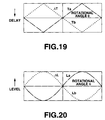
- FIG. 19 is an explanatory view for explaining operation of time difference adding unit used in virtual sound source transfer characteristic correcting means shown in FIG. 18 .
- FIG. 20 is an explanatory view for explaining operation of level difference adding unit used in the virtual sound source transfer characteristic correcting means shown in FIG. 18 .
- This headphone unit 40 comprises, as shown in FIG. 9 , a first input terminal 31 L supplied with audio signal Sal, a second input terminal 31 R supplied with audio signal Sar, A/D converters 32 L, 32 R for respectively converting respective audio signals Sal, Sar into digital signals, a virtual sound source reproducing section (unit) 50 for implementing a predetermined digital signal processing to the respective audio signals Sal, Sar converted into digital signals to output such digital signals in the state divided into two systems of synthetic audio signals Sbl, Sbr for left and right ears as stereo signal, D/A converters 34 L, 34 R for converting respective audio signals Sbl, Sbr outputted from this virtual sound source reproducing section 50 into analog signals, and amplifiers 35 L, 35 R for amplifying analog audio signals outputted from respective D/A converters 34 L, 34 R to deliver them to left and right headphone elements 36 a , 36 b of a headphone 36 .
- this headphone unit 40 there is employed such an approach to convert, by two A/D converters 32 L, 32 R, respective audio signals Sal, Sar from virtual sound sources respectively inputted from the first and second input terminals 31 L, 31 R into digital signals to implement digital signal processing, by the virtual sound source reproducing section 50 , to the respective audio signals Sal, Sar converted into digital signals to output such digital signals in the state divided into two systems of synthetic audio signals Sbl, Sbr for left and right ears to convert these synthetic audio signals Sbl, Sbr into analog signals by D/A converters 34 L, 34 R to amplify such analog signals by amplifiers 35 L, 35 R to deliver them to left and right headphone elements 36 a , 36 b of the headphone 36 to reproduce them.
- D/A converters 34 L, 34 R to amplify such analog signals by amplifiers 35 L, 35 R to deliver them to left and right headphone elements 36 a , 36 b of the headphone 36 to reproduce them.
- the virtual sound source reproducing section 50 used here may be provided within sound unit such as headphone 36 , etc., or may be provided within another sound equipment.
- the virtual sound source reproducing section 50 according to this invention used in the above-described headphone unit 40 is composed, as shown in FIG. 10 , of first signal processing means 51 such that when sounds corresponding to synthetic audio signals Sbl, Sbr for left and right ears are heard by the headphone 36 , it implements digital signal processing such that head outside sound image localization of virtual sound source is obtained with respect to a predetermined direction, and second signal processing means 52 for carrying out such a processing to perceive (sense) distance of sound image localization.
- impulse response portion (a) contributing to perception (sense) of position of sound source
- impulse response portion (b) contributing to perception (sense) of only distance up to sound source
- (a) is impulse response portion mainly indicating head related transfer function and is called head related transfer function region
- (b) is mainly impulse response portion mainly indicating reflected sound and is called reflected sound region.
- the impulse response portion (a) is about 10 to 30 ms.
- the first signal processing means 51 constituting the virtual sound source reproducing section 50 is constituted by, e.g., FIR type digital filter 45 as shown in FIG. 12 .
- This digital filter 45 is of configuration in which there are combined two FIR type digital filters adapted to output input signal Sal inputted through a first input terminal 53 as output signals of two systems and to output input signal Sar inputted through a second input terminal 54 as output signals of two systems, and respective digital filters are constituted as one filter block with cascade-connected plural delay elements 56 being as common element.
- the respective digital filters constituting FIR type digital filter 45 shown in FIG. 12 comprise cascade-connected plural delay elements 56 having a predetermined delay quantity, respective plural coefficient multipliers 57 , 58 for multiplying inputted audio signal and audio signals delayed at respective delay elements 57 by coefficients for carrying out convolution of impulse response, and respective plural adders 59 , 60 for adding audio signals outputted from the respective coefficient multipliers 57 , 58 .
- the respective stages of coefficient multipliers 57 ( 58 ) multiply input audio signal Sal and audio signals delayed in sequence at the respective stages of delay elements 56 by coefficients for carrying out convolution of impulse response to deliver them to adders 59 ( 60 ) of corresponding stages.
- the adders 59 ( 60 ) of respective stages add outputs of coefficient multipliers 57 ( 58 ) of corresponding stages to outputs of adders 59 ( 60 ) of the preceding stages to deliver them to adders 59 ( 60 ) of succeeding stages.
- the adder 59 ( 60 ) of the final stage carries out convolution of impulse response of transfer function HLL (HLR) with respect to audio signal Sal inputted through the input terminal 53 to form response signal Sb ll (Sb′lr) to deliver it to adder 61 ( 62 ).
- HLL transfer function
- adder of the final stage of digital filter supplied with audio signal Sar carries out convolution of impulse response of transfer function HRL (HRR) with respect to audio signal Sar inputted through the input terminal 54 to form response signal Sb′rl (Sb′rr) to deliver it to adder 61 ( 62 ).
- HRR transfer function transfer function
- this FIR type digital filter 45 constitutes filters of four systems by combining two digital filters to output signals of two systems
- delay element 56 cascade-connected can be shared by filters of two systems and the number of delay elements 56 used can be reduced to one half.
- Impulse response of the FIR type digital filter 45 shown in FIG. 12 forms head related transfer function region corresponding to one portion of respective impulse responses corresponding to the previously described transfer functions HLL, HLR, HRL, HRR of four systems which has been explained with reference to FIG. 2 , i.e., impulse response portion (a) mainly representing head related transfer function from the first (initial) response as shown in FIG. 11 .
- impulse responses (a) different from each other are convoluted at four systems of FIR type digital filter 45 .
- signal processing of input signal is carried out in accordance with impulse response from virtual sound source up to both ends of listener to reproduce it.
- response signal contributing to perception (sensing) of position of virtual sound source for localizing reproduction sound image at position of virtual sound source.
- Outputs of four systems of the FIR type digital filter 45 shown in FIG. 12 are respectively synthesized by adders 61 , 62 , and are respectively outputted from first and second output terminals 63 , 64 as initial response signals Sb′l, Sb′r for left and right ears.
- input signals Sal, Sar delayed by predetermined times by cascade-connected delay elements 56 , 56 constituting respective digital filters are synthesized by an adder 65 . Thereafter, the input signals thus obtained is delayed by a delay element 66 and is outputted from an output terminal 67 as synthetic delayed output signal.
- the delay element 66 additionally connected to the output terminal 67 serves to provide delay for timing correction when there are synthesized initial response signal from the first signal processing means 51 constituted by the FIR type digital filter 45 shown in FIG. 12 and reflected response signal from the second signal processing means 52 which will be described later.
- this delay element may be omitted, and this delay element 66 may be additionally connected to input terminal 68 of the second signal processing means 52 .
- synthetic delay signal outputted from the output terminal 67 of the FIR type digital filter 45 shown in FIG. 12 corresponds to synthetic delay output signal obtained by synthesizing delay output signals outputted from head related transfer function processing means supplied with plural audio signals, and is inputted to the input terminal 68 of the second signal processing means 52 constituted by FIR type digital filter 46 shown in FIG. 13 .
- FIR type digital filter 46 constituting second signal processing means 52 shown in FIG. 13 is caused to be of configuration to output input signal inputted through the input terminal 68 as output signals of 2 systems, and is caused to be of configuration as single filter block with cascade-connected plural delay elements 76 being as common elements.
- this FIR type digital filter 46 is composed of cascade-connected plural delay elements 76 having a predetermined delay quantity, respective plural coefficient multipliers 77 , 78 for multiplying input signal and signals delayed by the respective delay elements 76 by coefficients for carrying out convolution of impulse response, and respective plural adders 79 , 80 for adding signals outputted from the respective coefficient multipliers 77 , 78 .
- the coefficient multipliers 77 ( 78 ) of respective stages respectively multiply input signal and signals delayed in sequence at delay elements 76 of respective stages by coefficients for carrying out convolution of impulse response to deliver them to adders 79 ( 80 ) of corresponding stages.
- adders 79 ( 80 ) of respective stages add, to outputs of adders 79 ( 80 ) of the preceding stages, outputs of coefficient multipliers 77 ( 78 ) of corresponding stages to deliver them to the adders 79 ( 80 ) of the succeeding stages.
- adder 79 ( 80 ) of the final stage carries out convolution of impulse response indicating initial response sound with respect to signal inputted through input terminal 53 to form reflected sound to output this reflected sound through output terminal 81 ( 82 ).
- portions of different impulse responses of either two systems of impulse responses corresponding to the above-described transfer functions HLL, HLR, HRL, HRR of four systems are convoluted, and are outputted from first and second output terminals 81 , 82 .
- Respective outputs outputted from these output terminals 81 , 82 serve to form (b) reflected sound region which is impulse response portion mainly indicating the previously described reflected sound, and correspond to impulse response portion contributing to perception (sensing) of only distance from virtual sound source up to both ears of listener.
- impulse response portions of respective reflected sound regions are similar to each other in either system.
- such an approach may be employed to use impulse response portion of reflected sound regions of any two systems as coefficients of FIR type digital filter, to synthesize impulse response portions of reflected sound regions of any two systems, and to determine impulse response portion of reflected sound region of impulse responses corresponding to transfer functions from virtual sound source position except for the above, e.g., the front center.
- Output Sb′l from the first output terminal 63 and output Sb′r from the second terminal 64 of FIR type digital filter 45 shown in FIG. 12 constituting the first signal processing means 51 correspond to a pair of initial response signals contributing to position of the virtual sound source, and output signals respectively outputted from first output terminal 81 and second output terminal 82 of FIR type digital filter 46 shown in FIG. 13 constituting second signal processing means 52 correspond to a pair of reflected response signal contributing to perception (sensing) of only distance from virtual sound source up to both ears of listener.
- a pair of initial response signals outputted from first signal processing means 51 and a pair of reflected response signals outputted from the second signal processing means 52 are added at respective adders 84 , 85 constituting operation (computing) means 83 every signals corresponding to left and right signals in the case where stereo reproduction is carried out, and are respectively outputted from the first and second output terminals 86 , 87 as left ear synthetic audio signal Sbl and right ear synthetic audio signal Sbr.
- the left ear synthetic signal Sbl and the right ear synthetic signal Sbr respectively outputted from these output terminals 86 , 87 are returned (converted) into analog signals for a second time by D/A converters 34 L, 34 R of two systems shown in FIG.
- a second embodiment of the virtual sound source reproducing unit according to this invention will be described with reference to FIG. 14 .
- This virtual sound source reproducing unit 150 serves to obtain left ear synthetic audio signal Sbl and right ear synthetic audio signal Sbr respectively inputted from one sound source to both ears, and is adapted, for the purpose of localizing one sound source at arbitrary position, to realize, by digital filter, convolution of impulse response of two transfer functions from virtual sound source up to both ears.
- impulse response of the head related transfer function region is formed from head related transfer function of transfer function HL from the virtual sound source to the left ear and transfer function HR from the virtual sound source to the right ear
- respective coefficients are assigned to two FIR type digital filters to independently convolute them. This portion corresponds to first signal processing means 51 of the previously described virtual sound source unit 50 shown in FIG. 10 of the first embodiment.
- First signal processing means 151 of this virtual sound source unit 150 is FIR type digital filter constituted in order to output, as output signals of 2 systems, input signal Sa inputted through an input terminal 168 , and is constituted as one filter block with cascade-connected plural delay elements being commonly used.
- this FIR type digital filter is composed of cascade-connected plural delay elements 176 having a predetermined delay quantity, respective plural coefficient multipliers 177 , 178 for multiplying input signal and signals delayed by the respective delay elements 176 by coefficients for carrying out convolution of impulse response, and respective plural adders 179 , 180 for adding signals outputted from the respective coefficient multipliers 177 , 178 .
- Coefficient multipliers 177 ( 178 ) of respective stages respectively multiply input signal and signals delayed in sequence at delay elements 176 of respective stages by coefficients for carrying out convolution of impulse response to deliver them to adders 179 ( 180 ) of corresponding stages.
- the adders 179 ( 180 ) of the respective stages add, to outputs of adders 179 ( 180 ) of the preceding stages, outputs of coefficient multipliers 177 ( 178 ) of corresponding stages to deliver them to the adders 179 ( 180 ) of the succeeding stages.
- the adder 179 ( 180 ) of the final stage carries out convolution of impulse response indicating initial response sound with respect to signal inputted through input terminal 168 to form reflected sound to add reflected sounds at respective adders 184 , 185 constituting calculating means 183 every signals corresponding to left and right signals in the case of carrying out stereo reproduction to output them from first and second output terminals 186 , 187 as left ear synthetic audio signal Sbl and right synthetic audio signal Sbr.
- output signals delayed by delay elements 176 of FIR type digital filter constituting the above-described first signal processing means 151 are convoluted by coefficients common to impulse responses of respective reflected sound regions.
- the number of coefficients can be reduced, i.e., the number of multipliers can be reduced.
- Scale of signal processing can be reduced.
- This portion corresponds to second signal processing means 52 of the previously described virtual sound source unit 50 in the first embodiment.
- the second signal processing means 152 is composed of cascade-connected plural delay elements 116 having a predetermined delay quantity, plural coefficient multipliers 117 for multiplying output signal from the first signal processing means 151 inputted and signals delayed at respective delay elements 116 by coefficients for carrying out convolution of impulse response, and plural adders 118 for adding signals outputted from the respective coefficient multipliers 117 .
- the output signals processed by the second signal processing means 152 are respectively added to left ear synthetic audio signal Sbl and right ear synthetic audio signal Sbr, and are outputted from first and second output terminals 186 , 187 in the state where they are synthesized with left ear synthetic audio signal Sbl and right ear synthetic audio signal Sbr.
- impulse response portion of reflected sound region of any system may be used as coefficients of FIR type digital filter, impulse response portions of reflected sound regions of plural systems may be synthesized, and impulse response portion of reflected sound region of impulse response corresponding to transfer function from virtual sound source position except for the above, e.g., front and center may be determined to use it.
- a third embodiment of the virtual sound source reproducing device (unit) according to this invention will now be described with reference to FIG. 15 .
- This virtual sound source reproducing unit 250 shows the example in the case where it is assumed that, as shown in FIG. 15 , four sound sources are disposed substantially bilaterally symmetric with respect to listener and transfer characteristics to left and right ears of listener are substantially symmetric.
- the signal processing means shown in FIG. 16 constituting virtual sound source reproducing unit 250 is constituted in a manner to directly obtain transfer function with respect to two virtual sound sources symmetrically disposed by the FIR type digital filters in accordance with the above-mentioned formula (3).
- a pair of input signals respectively inputted from a pair of input terminals 201 , 202 are inputted to an adding/subtracting processing section 274 .
- respective sum and difference signals are formed by the adding/subtracting processing section 274 .
- These sum and difference signals respectively are caused to undergo signal processing by first and second FIR type digital filters 203 , 204 .
- respective signals outputted from the first and second FIR type digital filters 203 , 204 are caused to undergo adding/subtracting processing by the adding/subtracting processing section 275 .
- respective sum and difference signals are outputted from first and second output terminals 205 , 206 as a pair of output signals.
- the first and second FIR type digital filters 203 , 204 used here are constituted similarly to the previously described digital filter shown in FIG. 5 , and respective digital filters 203 , 204 are composed, as shown in FIG. 16 , of cascade-connected plural delay elements 216 having a predetermined delay quantity, plural coefficient multipliers 217 for multiplying inputted audio signal and audio signals delayed at respective delay elements 216 by coefficients for carrying out convolution of impulse response, and plural adders 218 for adding audio signals outputted from the respective coefficient multipliers 217 .
- Coefficient multipliers 217 of respective stages respectively multiply input audio signal Sal and audio signals delayed in sequence at the delay elements 216 of respective stages by coefficients for carrying out convolution of impulse response to deliver them to adders 218 of corresponding stages.
- the adders 218 of respective stages add, to outputs of the adders of the preceding stages, outputs of coefficient multipliers 217 of the corresponding stages to deliver them to the adders 218 of the succeeding stages.
- the adder 218 of the final stage carries out convolution of impulse response of transfer function HLL (HLR) with respect to audio signal Sal (Sar) inputted through the input terminal 201 ( 202 ) to form left ear audio signal Sbll (right ear audio signal Sblr) to output it to an adding/subtracting processing section 275 .
- HLL transfer function
- the virtual sound source unit 250 By constituting the virtual sound source unit 250 in a manner as shown in FIG. 15 , with respect to the sound source assumed to be bilaterally symmetric, also in the signal processing for reproducing virtual sound source, similarly to the first signal processing means 51 and the second signal processing means 52 which have been described with reference to FIG. 10 in the previously described first embodiment, scale of the signal processing means can be greatly reduced. While the case where the virtual sound source is reproduced when the number of sound sources is four in this example has been described, this invention may be applied to a larger number of sound sources generally bilaterally symmetrically disposed, thus making it possible to reproduce the virtual sound source.
- adding/subtracting processing section 274 may be provided for this signal to input both input signals in the state equally distributed, or to equally synthesize such signal with audio signal of other symmetric sound source to input it to adding/subtracting processing section 274 .
- a fourth embodiment of a virtual sound source reproducing unit 350 according to this invention will now be described with reference to FIG. 17 .
- This headphone unit 300 using the virtual sound source reproducing unit 350 is provided with virtual sound source transfer characteristic correcting means 310 corresponding to the virtual sound source reproducing unit according to this invention.
- Virtual sound source reproducing unit for reproducing the previously described four bilaterally symmetrically disposed virtual sound sources shown in FIG. 15 of the third embodiment is constituted as headphone unit 300 .
- This headphone unit 300 comprises adding/subtracting processing section 374 including two adding/subtracting processing circuits 374 a , 374 b for carrying out adding/subtracting processing of a pair of input signals respectively inputted from a pair of input terminals 311 , 312 .
- the two adding/subtracting processing circuits 374 a , 374 b constituting this adding/subtracting processing section 374 carry out adding/subtracting processing of pairs of input signals respectively inputted to form respective sum and difference signals.
- the virtual sound source transfer characteristic correcting means 310 constituting this headphone unit 300 comprises a rotational angle speed sensor 370 attached on a headphone 306 in order to detect rotational angle speed, i.e., displacement speed of the head portion of listener who has attached the headphone 306 , a band-limiting filter 371 for band-limiting output of this rotational angle speed sensor 370 , an A/D converter 372 for converting band-limited analog signal output into digital signal, and a microprocessor 373 having rotational movement angle calculation function for calculating rotational movement speed from the front direction of listener who has attached headphone 306 , i.e., position change quantity of both ears from digital signal output outputted from the A/D converter 372 .
- the rotational angle speed sensor 370 and the microprocessor 373 constitute characteristic change means comprising head portion rotational angle detecting means for detecting rotational angle speed of the head portion of listener, displacement quantity calculating means for calculating position change quantities of both ears of listener from this head portion rotational angle detecting means, and characteristic control means for changing response characteristic of the head related transfer function processing means in accordance with output of this displacement calculating means, and constitutes response characteristic control means 301 .
- virtual sound source transfer correcting means 310 of this invention if there is employed such means to detect rotation of head portion or change of positions of both ears of listener, etc. to carry out a predetermined control, this means is not limited to the above-described detecting means.
- rotational angle speed sensor 370 attached at the headphone 306 When listener who has attached the headphone 306 rotates both ears in left and right directions so that the headphone 306 is rotationally moved, rotational angle speed sensor 370 attached at the headphone 306 outputs, as detection output, voltage proportional to its angular speed.
- This output signal is band-limited by band-limiting filter 371 , and is then converted into digital signal at A/D converter 372 .
- the digital signal thus obtained is inputted to microprocessor 373 .
- the microprocessor 373 makes sampling, at fixed time interval, inputted output signal of the A/D converter 372 thereafter to integrate it to convert it into angular data to calculate rotational angle for rotating virtual sound source from the angular data to transfer corresponding response characteristic control data to first signal processing means 351 .
- the first signal processing means 351 used here updates signal processing contents of audio signals reproduced from four virtual sound sources in accordance with response characteristic control data calculated at the microprocessor 373 to carry out digital signal processing for localizing sound images of virtual sound sources at suitable positions of the outside of the head and the front portion thereof, i.e., change of parameters (coefficient data of coefficient multipliers) of FIR type digital filter corresponding to head related transfer function region.
- digital circuit capable of changing coefficients of FIR type digital filter corresponding to the head related transfer function region is prepared within the first signal processing means 351 . Thereafter, output of the first signal processing means 351 is arithmetically processed together with output through signal processing corresponding to reflected sound region obtained by second signal processing means 352 .
- a pair of computed output signals are inputted to adding/subtracting processing section 375 .
- a pair of processing signals which have been caused to undergo adding/subtracting processing by this adding/subtracting processing section 375 are outputted as sum signal and difference signal.
- a pair of processing signals which have been caused to undergo adding/subtracting processing by the adding/subtracting processing section 375 are respectively outputted to two D/A converters 304 L, 304 R.
- Both ear synthetic audio signals Sbl, Sbr returned (converted) into analog signal for a second time by the two D/A converters 304 L, 304 R are respectively delivered to left and right headphone elements 306 a , 306 b of the headphone 306 through amplifiers 305 L, 305 R and are reproduced, thus providing optimum out-of-head localization feeling in correspondence with position change of both ears to listener who listens to it.
- Respective FIR type digital filters constituting the first signal processing means 351 constitute head related transfer functions of transfer functions of HLL, HLR, HRL, HRR ranging from speakers to both ears of the listener which have been described with reference to FIG. 2 , and these head related transfer functions are not fixed in practice, but change with movement of the head of listener. Change in synchronism with movement of the head of this head related transfer function constitutes cause for allowing listener to recognize position of sound image. Accordingly, it is known that precisely reproducing such operation contributes improvement in the quality of sound image localization.
- the head related transfer function is realized as described above by updating, on the real time basis, coefficients of respective FIR type digital filters by the microprocessor 373 .
- coefficients of the FIR type digital filter corresponding to the head related transfer function region contributing to perception (sensing) of position are updated on the real time basis, and coefficients of FIR type digital filter corresponding to reflected sound region contributing to perception (sensing) of distance remain to be fixed. Accordingly, as compared to the case where all coefficients of FIR type digital filter constituting the transfer function, coefficient memory capacity necessary for coefficient updating can be reduced to much degree.
- a fifth embodiment of a virtual sound source reproducing unit 450 according to this invention will now be described with reference to FIG. 18 .
- This virtual sound source unit 450 serves to control response characteristic corresponding to the head related transfer function region by the virtual sound source transfer characteristic correcting means 310 shown in FIG. 17 , and is related to first signal processing means 451 of the virtual sound source reproducing unit 450 according to this invention in connection with two virtual sound sources.
- reference numeral 402 in FIG. 18 indicates only the portion for changing parameters related to virtual sound source position to be reproduced of the first signal processing means 451 of the virtual sound source transfer characteristic correcting means 310 , and the description of the response characteristic control means 301 will be omitted since the operation is similar to that which has been described in the fourth embodiment.
- first to fourth FIR type digital filters 90 to 93 constituting first signal processing means 451 shown in FIG. 18 , there are used, e.g., digital filters similar to the digital filters which have been explained with reference to FIG. 12 in the first embodiment.
- the respective FIR type digital filters 90 to 93 realize impulse response portions corresponding to the previously described head related transfer function regions of HLL, HLR, HRL, HRR up to both ears in the case where listener is directed in fixed direction, e.g., at front side from speaker which has been described with reference to FIG. 2 .
- the first and second FIR type digital filters 90 , 91 are supplied with audio signal through first input terminal 411 from one sound source, and the third and fourth FIR type digital filters 92 , 93 are supplied with audio signal through second input terminal 412 from the other one sound source.
- Outputs of the first FIR type digital filter 90 and the third FIR type digital filter 92 are added, and outputs of the second FIR type digital filter 91 and the fourth FIR type digital filter 93 are added, and these outputs thus added are respectively outputted to time difference adding sections 484 , 485 . Further, respective outputs are delivered to level difference adding sections 483 , 486 . Their outputs are outputted as output signals of left and right two systems through first and second output terminals 480 , 481 similarly to the case where explanation has been given with reference to FIG. 10 in the first embodiment and are inputted to the second signal processing means. Thus, these output signals are added. In addition, output signal from the first signal processing means 451 is inputted to the second signal processing means 402 through third output terminal 482 . Processing similar to that at the previously described first embodiment is carried out.
- time difference adding sections 484 , 485 and level difference adding sections 483 , 486 in the case where, e.g., listener rotates his head portion in a right direction, audio signal reached to the left ear becomes faster than audio signal reached to the right ear, and the left ear becomes close to the sound source and the right ear becomes away from the sound source. For this reason, level of audio signal which is reached to the left ear becomes higher than that of audio signal which is reached to the right ear.
- change of transfer function resulting from the fact that head of listener is moved is represented by time difference and level difference of audio signal reached to the both ears to control these differences reached to the both ears by microprocessor, thereby making it possible to simulate and simplify dynamic transfer function.
- FIG. 19 shows delay time characteristic of the time difference adding sections 484 , 485 , wherein delay time added at the time difference adding section 484 for the left side is represented by characteristic curve Ta of single dotted lines and delay time added at the time difference adding section 485 for right side is represented by characteristic curve Tb of broken lines.
- the characteristic curves Ta and Tb are curves having increase/decrease directions entirely opposite to each other with respect to rotational direction of head portion of listener M.
- time difference adding sections 484 , 485 it is possible to realize change of time difference from sound source to both ears by using sound device such as headphone, etc. which is similar to the case where listener M listens to sound from sound source disposed within the range of forward 180 degrees while rotating his head in left and right directions as has been explained with reference to the previously mentioned FIG. 2 .
- FIG. 20 shows relative level characteristic of level difference adding sections 483 , 486 .
- Level difference added at level difference adding section 483 for left side is indicated by characteristic curve La of single dotted lines and level difference added at level difference adding section 486 for right side is indicated by characteristic curve Lb of broken lines.
- characteristic curve La of single dotted lines
- Lb level difference added at level difference adding section 486 for right side
- the characteristic curves La, Lb are curves having increase/decrease directions entirely opposite to each other with respect to rotational direction of the head portion of listener M.
- the virtual sound source reproducing device of this invention may be provided at sound apparatus such as headphone unit or speaker unit, etc., and may be provided at sound equipments for handling sound such as audio equipment, etc. Also in both cases, it is clear that the virtual sound source can be suitably formed and the scale of the configuration of the sound apparatus and sound equipment can also become compact.
- the virtual sound source reproducing device is composed of first signal processing means and second signal processing means, wherein the first signal processing means is used to mainly represent the portion of head related transfer function to have ability to reproduce the portion of impulse response capable of perceiving (sensing) position of virtual sound source to localize sound image at the outside of head portion in a desired direction, and the second signal processing means is used to reproduce the portion of impulse response to perceive (sense) only distance of the virtual sound source to add reflected sound, etc.
- the first signal processing means is used to mainly represent the portion of head related transfer function to have ability to reproduce the portion of impulse response capable of perceiving (sensing) position of virtual sound source to localize sound image at the outside of head portion in a desired direction
- the second signal processing means is used to reproduce the portion of impulse response to perceive (sense) only distance of the virtual sound source to add reflected sound, etc.
- virtual sound source transfer function correcting means to detect displacement speeds of both ears by using rotational angular sensor or microprocessor to calculate change of positions of both ears for the purpose of coping with change of transfer function from virtual sound source to both ears resulting from the fact that listener moves his head in left and right directions to directly control coefficients of digital filter corresponding to the head related transfer function region of first signal processing means of the above-described virtual sound source reproducing device, or to indirectly control impulse response portion corresponding to the above-described head related transfer function region by using the time difference adding section and the level difference adding section added to the succeeding stage of the first signal processing means.
- the virtual sound source reproducing device when the virtual sound source reproducing device according to this invention is provided at sound apparatus such as headphone unit or speaker unit, etc., or sound equipment such as audio unit, etc., miniaturization of the sound apparatus and the sound equipment and low power consumption can be realized.
Landscapes
- Engineering & Computer Science (AREA)
- Physics & Mathematics (AREA)
- Acoustics & Sound (AREA)
- Signal Processing (AREA)
- Multimedia (AREA)
- Health & Medical Sciences (AREA)
- Audiology, Speech & Language Pathology (AREA)
- General Health & Medical Sciences (AREA)
- Stereophonic System (AREA)
Abstract
Description
SL={(HOL×HRR−HOR×HRL)/(HLL×HRR−HLR×HRL)}×SO (1)
SR={(HOR×HLL−HOL×HLR)/(HLL×HRR−HLR×HRL)}×SO (2)
HLR=HRL
HLL=HRR (3)
Claims (17)
Applications Claiming Priority (3)
| Application Number | Priority Date | Filing Date | Title |
|---|---|---|---|
| JP2033899 | 1999-01-28 | ||
| JP11-020338 | 1999-01-28 | ||
| PCT/JP2000/000421 WO2000045619A1 (en) | 1999-01-28 | 2000-01-27 | Virtual sound source device and acoustic device comprising the same |
Publications (1)
| Publication Number | Publication Date |
|---|---|
| US7917236B1 true US7917236B1 (en) | 2011-03-29 |
Family
ID=12024364
Family Applications (1)
| Application Number | Title | Priority Date | Filing Date |
|---|---|---|---|
| US09/647,444 Expired - Fee Related US7917236B1 (en) | 1999-01-28 | 2000-01-27 | Virtual sound source device and acoustic device comprising the same |
Country Status (4)
| Country | Link |
|---|---|
| US (1) | US7917236B1 (en) |
| JP (1) | JP4744695B2 (en) |
| KR (1) | KR100713666B1 (en) |
| WO (1) | WO2000045619A1 (en) |
Cited By (11)
| Publication number | Priority date | Publication date | Assignee | Title |
|---|---|---|---|---|
| US20090022328A1 (en) * | 2007-07-19 | 2009-01-22 | Fraunhofer-Gesellschafr Zur Forderung Der Angewandten Forschung E.V. | Method and apparatus for generating a stereo signal with enhanced perceptual quality |
| US20150222453A1 (en) * | 2014-01-31 | 2015-08-06 | Qualcomm Incorporated | Instruction and method for fused rake-finger operation on a vector processor |
| US9473871B1 (en) * | 2014-01-09 | 2016-10-18 | Marvell International Ltd. | Systems and methods for audio management |
| US20170295446A1 (en) * | 2016-04-08 | 2017-10-12 | Qualcomm Incorporated | Spatialized audio output based on predicted position data |
| US9794722B2 (en) * | 2015-12-16 | 2017-10-17 | Oculus Vr, Llc | Head-related transfer function recording using positional tracking |
| US20200045491A1 (en) * | 2018-08-06 | 2020-02-06 | Facebook Technologies, Llc | Customizing head-related transfer functions based on monitored responses to audio content |
| US10645520B1 (en) * | 2019-06-24 | 2020-05-05 | Facebook Technologies, Llc | Audio system for artificial reality environment |
| US20210021698A1 (en) * | 2014-12-18 | 2021-01-21 | Finewell Co., Ltd. | Cartilage conduction hearing device using an electromagnetic vibration unit, and electromagnetic vibration unit |
| US20230007431A1 (en) * | 2018-05-29 | 2023-01-05 | Staton Techiya Llc | Location based audio signal message processing |
| US20240022854A1 (en) * | 2021-04-12 | 2024-01-18 | Panasonic Intellectual Property Corporation Of America | Sound reproduction method, sound reproduction device, and recording medium |
| US12395810B2 (en) | 2018-04-09 | 2025-08-19 | Dolby International Ab | Methods, apparatus and systems for three degrees of freedom (3DOF+) extension of MPEG-H 3D audio |
Families Citing this family (6)
| Publication number | Priority date | Publication date | Assignee | Title |
|---|---|---|---|---|
| AUPQ941600A0 (en) * | 2000-08-14 | 2000-09-07 | Lake Technology Limited | Audio frequency response processing sytem |
| KR20060022968A (en) | 2004-09-08 | 2006-03-13 | 삼성전자주식회사 | Sound Regeneration Device and Sound Regeneration Method |
| JP2006229547A (en) * | 2005-02-17 | 2006-08-31 | Matsushita Electric Ind Co Ltd | Sound image out-of-head localization apparatus and sound image out-of-head localization method |
| KR100818660B1 (en) | 2007-03-22 | 2008-04-02 | 광주과학기술원 | 3D sound generator for short range model |
| CN118339856A (en) * | 2021-12-09 | 2024-07-12 | 松下电器(美国)知识产权公司 | Sound processing device, sound processing method, and program |
| KR20250113835A (en) * | 2024-01-19 | 2025-07-28 | 삼성전자주식회사 | Electronic device and control method of the electronic device |
Citations (24)
| Publication number | Priority date | Publication date | Assignee | Title |
|---|---|---|---|---|
| US4130727A (en) * | 1977-06-29 | 1978-12-19 | Teledyne, Inc. | Loudspeaker equalization |
| JPS55150700A (en) | 1979-05-14 | 1980-11-22 | Matsushita Electric Ind Co Ltd | Stereophonic reproducing system |
| US4509191A (en) * | 1982-09-20 | 1985-04-02 | Scholz Research & Development | Electronic stereo reverberation device |
| JPH01120999A (en) | 1987-11-04 | 1989-05-12 | Sony Corp | Audio reproducing device |
| US5034983A (en) * | 1987-10-15 | 1991-07-23 | Cooper Duane H | Head diffraction compensated stereo system |
| JPH04149598A (en) | 1990-10-12 | 1992-05-22 | Pioneer Electron Corp | Sound field correction device |
| JPH04253097A (en) | 1991-01-30 | 1992-09-08 | Fujitsu Ten Ltd | Reverberation addition device |
| US5371799A (en) * | 1993-06-01 | 1994-12-06 | Qsound Labs, Inc. | Stereo headphone sound source localization system |
| US5381482A (en) * | 1992-01-30 | 1995-01-10 | Matsushita Electric Industrial Co., Ltd. | Sound field controller |
| JPH0795696A (en) | 1993-09-24 | 1995-04-07 | Yamaha Corp | Image normal positioning device |
| JPH08146974A (en) | 1994-11-15 | 1996-06-07 | Yamaha Corp | Sound image and sound field controller |
| US5572591A (en) * | 1993-03-09 | 1996-11-05 | Matsushita Electric Industrial Co., Ltd. | Sound field controller |
| JPH0993700A (en) | 1995-09-28 | 1997-04-04 | Sony Corp | Video and audio playback device |
| JPH0990963A (en) | 1995-09-20 | 1997-04-04 | Hitachi Ltd | SOUND INFORMATION PROVIDING DEVICE AND SOUND INFORMATION SELECTION METHOD |
| US5621801A (en) * | 1993-06-11 | 1997-04-15 | Yamaha Corporation | Reverberation effect imparting system |
| JPH10136499A (en) | 1996-09-04 | 1998-05-22 | Victor Co Of Japan Ltd | Surround signal processing method, image and sound reproducing method, surround signal processor, surround signal processing program recorded recording medium, method for transmitting and receiving processing program, method, device and medium for recording to recording medium, and method for transmitting and receiving recorded data |
| JPH10201000A (en) | 1997-01-09 | 1998-07-31 | Sony Corp | FIR filter, headphone device and speaker device using the same |
| US5854843A (en) * | 1995-06-07 | 1998-12-29 | The United States Of America As Represented By The Secretary Of The Air Force | Virtual navigator, and inertial angular measurement system |
| US5991085A (en) * | 1995-04-21 | 1999-11-23 | I-O Display Systems Llc | Head-mounted personal visual display apparatus with image generator and holder |
| US6021206A (en) * | 1996-10-02 | 2000-02-01 | Lake Dsp Pty Ltd | Methods and apparatus for processing spatialised audio |
| US6084556A (en) * | 1995-11-28 | 2000-07-04 | Vega Vista, Inc. | Virtual computer monitor |
| US6091894A (en) * | 1995-12-15 | 2000-07-18 | Kabushiki Kaisha Kawai Gakki Seisakusho | Virtual sound source positioning apparatus |
| US6243476B1 (en) * | 1997-06-18 | 2001-06-05 | Massachusetts Institute Of Technology | Method and apparatus for producing binaural audio for a moving listener |
| US6718042B1 (en) * | 1996-10-23 | 2004-04-06 | Lake Technology Limited | Dithered binaural system |
Family Cites Families (1)
| Publication number | Priority date | Publication date | Assignee | Title |
|---|---|---|---|---|
| JPH0746700A (en) * | 1993-07-30 | 1995-02-14 | Victor Co Of Japan Ltd | Signal processor and sound field processor using same |
-
2000
- 2000-01-27 US US09/647,444 patent/US7917236B1/en not_active Expired - Fee Related
- 2000-01-27 WO PCT/JP2000/000421 patent/WO2000045619A1/en not_active Ceased
- 2000-01-27 KR KR1020007010557A patent/KR100713666B1/en not_active Expired - Fee Related
- 2000-01-27 JP JP2000596755A patent/JP4744695B2/en not_active Expired - Fee Related
Patent Citations (24)
| Publication number | Priority date | Publication date | Assignee | Title |
|---|---|---|---|---|
| US4130727A (en) * | 1977-06-29 | 1978-12-19 | Teledyne, Inc. | Loudspeaker equalization |
| JPS55150700A (en) | 1979-05-14 | 1980-11-22 | Matsushita Electric Ind Co Ltd | Stereophonic reproducing system |
| US4509191A (en) * | 1982-09-20 | 1985-04-02 | Scholz Research & Development | Electronic stereo reverberation device |
| US5034983A (en) * | 1987-10-15 | 1991-07-23 | Cooper Duane H | Head diffraction compensated stereo system |
| JPH01120999A (en) | 1987-11-04 | 1989-05-12 | Sony Corp | Audio reproducing device |
| JPH04149598A (en) | 1990-10-12 | 1992-05-22 | Pioneer Electron Corp | Sound field correction device |
| JPH04253097A (en) | 1991-01-30 | 1992-09-08 | Fujitsu Ten Ltd | Reverberation addition device |
| US5381482A (en) * | 1992-01-30 | 1995-01-10 | Matsushita Electric Industrial Co., Ltd. | Sound field controller |
| US5572591A (en) * | 1993-03-09 | 1996-11-05 | Matsushita Electric Industrial Co., Ltd. | Sound field controller |
| US5371799A (en) * | 1993-06-01 | 1994-12-06 | Qsound Labs, Inc. | Stereo headphone sound source localization system |
| US5621801A (en) * | 1993-06-11 | 1997-04-15 | Yamaha Corporation | Reverberation effect imparting system |
| JPH0795696A (en) | 1993-09-24 | 1995-04-07 | Yamaha Corp | Image normal positioning device |
| JPH08146974A (en) | 1994-11-15 | 1996-06-07 | Yamaha Corp | Sound image and sound field controller |
| US5991085A (en) * | 1995-04-21 | 1999-11-23 | I-O Display Systems Llc | Head-mounted personal visual display apparatus with image generator and holder |
| US5854843A (en) * | 1995-06-07 | 1998-12-29 | The United States Of America As Represented By The Secretary Of The Air Force | Virtual navigator, and inertial angular measurement system |
| JPH0990963A (en) | 1995-09-20 | 1997-04-04 | Hitachi Ltd | SOUND INFORMATION PROVIDING DEVICE AND SOUND INFORMATION SELECTION METHOD |
| JPH0993700A (en) | 1995-09-28 | 1997-04-04 | Sony Corp | Video and audio playback device |
| US6084556A (en) * | 1995-11-28 | 2000-07-04 | Vega Vista, Inc. | Virtual computer monitor |
| US6091894A (en) * | 1995-12-15 | 2000-07-18 | Kabushiki Kaisha Kawai Gakki Seisakusho | Virtual sound source positioning apparatus |
| JPH10136499A (en) | 1996-09-04 | 1998-05-22 | Victor Co Of Japan Ltd | Surround signal processing method, image and sound reproducing method, surround signal processor, surround signal processing program recorded recording medium, method for transmitting and receiving processing program, method, device and medium for recording to recording medium, and method for transmitting and receiving recorded data |
| US6021206A (en) * | 1996-10-02 | 2000-02-01 | Lake Dsp Pty Ltd | Methods and apparatus for processing spatialised audio |
| US6718042B1 (en) * | 1996-10-23 | 2004-04-06 | Lake Technology Limited | Dithered binaural system |
| JPH10201000A (en) | 1997-01-09 | 1998-07-31 | Sony Corp | FIR filter, headphone device and speaker device using the same |
| US6243476B1 (en) * | 1997-06-18 | 2001-06-05 | Massachusetts Institute Of Technology | Method and apparatus for producing binaural audio for a moving listener |
Cited By (19)
| Publication number | Priority date | Publication date | Assignee | Title |
|---|---|---|---|---|
| US8064624B2 (en) | 2007-07-19 | 2011-11-22 | Fraunhofer-Gesellschaft Zur Foerderung Der Angewandten Forschung E.V. | Method and apparatus for generating a stereo signal with enhanced perceptual quality |
| US20090022328A1 (en) * | 2007-07-19 | 2009-01-22 | Fraunhofer-Gesellschafr Zur Forderung Der Angewandten Forschung E.V. | Method and apparatus for generating a stereo signal with enhanced perceptual quality |
| US9473871B1 (en) * | 2014-01-09 | 2016-10-18 | Marvell International Ltd. | Systems and methods for audio management |
| US20150222453A1 (en) * | 2014-01-31 | 2015-08-06 | Qualcomm Incorporated | Instruction and method for fused rake-finger operation on a vector processor |
| US9276778B2 (en) * | 2014-01-31 | 2016-03-01 | Qualcomm Incorporated | Instruction and method for fused rake-finger operation on a vector processor |
| US20210021698A1 (en) * | 2014-12-18 | 2021-01-21 | Finewell Co., Ltd. | Cartilage conduction hearing device using an electromagnetic vibration unit, and electromagnetic vibration unit |
| US11601538B2 (en) * | 2014-12-18 | 2023-03-07 | Finewell Co., Ltd. | Headset having right- and left-ear sound output units with through-holes formed therein |
| US9794722B2 (en) * | 2015-12-16 | 2017-10-17 | Oculus Vr, Llc | Head-related transfer function recording using positional tracking |
| US10979843B2 (en) * | 2016-04-08 | 2021-04-13 | Qualcomm Incorporated | Spatialized audio output based on predicted position data |
| US20170295446A1 (en) * | 2016-04-08 | 2017-10-12 | Qualcomm Incorporated | Spatialized audio output based on predicted position data |
| US12395810B2 (en) | 2018-04-09 | 2025-08-19 | Dolby International Ab | Methods, apparatus and systems for three degrees of freedom (3DOF+) extension of MPEG-H 3D audio |
| US20230007431A1 (en) * | 2018-05-29 | 2023-01-05 | Staton Techiya Llc | Location based audio signal message processing |
| US11665499B2 (en) * | 2018-05-29 | 2023-05-30 | Staton Techiya Llc | Location based audio signal message processing |
| US12041438B2 (en) | 2018-05-29 | 2024-07-16 | Staton Techiya Llc | Location based audio signal message processing |
| US10638251B2 (en) * | 2018-08-06 | 2020-04-28 | Facebook Technologies, Llc | Customizing head-related transfer functions based on monitored responses to audio content |
| US20200045491A1 (en) * | 2018-08-06 | 2020-02-06 | Facebook Technologies, Llc | Customizing head-related transfer functions based on monitored responses to audio content |
| US10645520B1 (en) * | 2019-06-24 | 2020-05-05 | Facebook Technologies, Llc | Audio system for artificial reality environment |
| US10959038B2 (en) | 2019-06-24 | 2021-03-23 | Facebook Technologies, Llc | Audio system for artificial reality environment |
| US20240022854A1 (en) * | 2021-04-12 | 2024-01-18 | Panasonic Intellectual Property Corporation Of America | Sound reproduction method, sound reproduction device, and recording medium |
Also Published As
| Publication number | Publication date |
|---|---|
| JP4744695B2 (en) | 2011-08-10 |
| KR100713666B1 (en) | 2007-05-02 |
| KR20010042151A (en) | 2001-05-25 |
| WO2000045619A1 (en) | 2000-08-03 |
Similar Documents
| Publication | Publication Date | Title |
|---|---|---|
| US7917236B1 (en) | Virtual sound source device and acoustic device comprising the same | |
| US6839438B1 (en) | Positional audio rendering | |
| EP1680941B1 (en) | Multi-channel audio surround sound from front located loudspeakers | |
| JP3687099B2 (en) | Video signal and audio signal playback device | |
| US6611603B1 (en) | Steering of monaural sources of sound using head related transfer functions | |
| US7382885B1 (en) | Multi-channel audio reproduction apparatus and method for loudspeaker sound reproduction using position adjustable virtual sound images | |
| US6970569B1 (en) | Audio processing apparatus and audio reproducing method | |
| JP3266020B2 (en) | Sound image localization method and apparatus | |
| US5526429A (en) | Headphone apparatus having means for detecting gyration of user's head | |
| JPH0970094A (en) | Headphone equipment | |
| US20060062410A1 (en) | Method, apparatus, and computer readable medium to reproduce a 2-channel virtual sound based on a listener position | |
| EP0438281A2 (en) | Acoustic signal reproducing apparatus | |
| JPWO1995022235A1 (en) | Video and audio signal reproducing device | |
| JP2001507879A (en) | Stereo sound expander | |
| JP5754595B2 (en) | Trans oral system | |
| JPWO2000045619A1 (en) | Virtual sound source device and acoustic device using the same | |
| JPH0946800A (en) | Sound image controller | |
| JP2751166B2 (en) | Headphone equipment | |
| JP2671329B2 (en) | Audio player | |
| JP2900985B2 (en) | Headphone playback device | |
| JP4949706B2 (en) | Sound image localization apparatus and sound image localization method | |
| JP2910891B2 (en) | Sound signal processing device | |
| JPH05199596A (en) | Sound field playback device | |
| EP0464217B1 (en) | Apparatus for reproducing acoustic signals | |
| JP2947456B2 (en) | Surround signal processing device and video / audio reproduction device |
Legal Events
| Date | Code | Title | Description |
|---|---|---|---|
| AS | Assignment |
Owner name: SONY CORPORATION, JAPAN Free format text: ASSIGNMENT OF ASSIGNORS INTEREST;ASSIGNOR:YAMADA, YUJI;REEL/FRAME:014435/0613 Effective date: 20000914 |
|
| FEPP | Fee payment procedure |
Free format text: PAYER NUMBER DE-ASSIGNED (ORIGINAL EVENT CODE: RMPN); ENTITY STATUS OF PATENT OWNER: LARGE ENTITY Free format text: PAYOR NUMBER ASSIGNED (ORIGINAL EVENT CODE: ASPN); ENTITY STATUS OF PATENT OWNER: LARGE ENTITY |
|
| STCF | Information on status: patent grant |
Free format text: PATENTED CASE |
|
| CC | Certificate of correction | ||
| FPAY | Fee payment |
Year of fee payment: 4 |
|
| FEPP | Fee payment procedure |
Free format text: MAINTENANCE FEE REMINDER MAILED (ORIGINAL EVENT CODE: REM.); ENTITY STATUS OF PATENT OWNER: LARGE ENTITY |
|
| LAPS | Lapse for failure to pay maintenance fees |
Free format text: PATENT EXPIRED FOR FAILURE TO PAY MAINTENANCE FEES (ORIGINAL EVENT CODE: EXP.); ENTITY STATUS OF PATENT OWNER: LARGE ENTITY |
|
| STCH | Information on status: patent discontinuation |
Free format text: PATENT EXPIRED DUE TO NONPAYMENT OF MAINTENANCE FEES UNDER 37 CFR 1.362 |
|
| FP | Lapsed due to failure to pay maintenance fee |
Effective date: 20190329 |