US7916790B2 - Pixel compensation method for an image sensor - Google Patents
Pixel compensation method for an image sensor Download PDFInfo
- Publication number
- US7916790B2 US7916790B2 US11/420,612 US42061206A US7916790B2 US 7916790 B2 US7916790 B2 US 7916790B2 US 42061206 A US42061206 A US 42061206A US 7916790 B2 US7916790 B2 US 7916790B2
- Authority
- US
- United States
- Prior art keywords
- block
- pixels
- compensation
- frequency response
- pixel
- Prior art date
- Legal status (The legal status is an assumption and is not a legal conclusion. Google has not performed a legal analysis and makes no representation as to the accuracy of the status listed.)
- Expired - Fee Related, expires
Links
Images


Classifications
-
- H—ELECTRICITY
- H04—ELECTRIC COMMUNICATION TECHNIQUE
- H04N—PICTORIAL COMMUNICATION, e.g. TELEVISION
- H04N25/00—Circuitry of solid-state image sensors [SSIS]; Control thereof
- H04N25/60—Noise processing, e.g. detecting, correcting, reducing or removing noise
- H04N25/67—Noise processing, e.g. detecting, correcting, reducing or removing noise applied to fixed-pattern noise, e.g. non-uniformity of response
- H04N25/671—Noise processing, e.g. detecting, correcting, reducing or removing noise applied to fixed-pattern noise, e.g. non-uniformity of response for non-uniformity detection or correction
Definitions
- the present invention relates to a pixel compensation method for an image sensor, more particularly to a method for performing compensation of response intensities of pixels in a pattern obtained by an image sensor.
- An image-capturing device such as a digital camera, includes an image sensor.
- the image sensor is typically a complementary metal oxide semiconductor (CMOS) sensor or a charge coupled device (CCD) sensor.
- CMOS complementary metal oxide semiconductor
- CCD charge coupled device
- the image sensor converts light into electrons at photosites.
- a color filter array such as a Bayer filter
- a demosaicing algorithm is then used to convert the mosaic of separate colors into an equally sized mosaic of true colors.
- the true color of a single pixel can be determined by averaging the values from the closest surrounding pixels by using interpolation techniques.
- the response intensities of the pixels may be uneven at areas where there should be uniformity due to such factors as lighting, circuit design characteristics, color differences, and defects in a lens of the image-capturing device.
- Such an adverse affect to the response intensities of the pixels is particularly marked among pixels of different columns and rows of the obtained pattern. Differences in pixel response intensities may cause color spots of localized color unevenness.
- the object of this invention is to provide a pixel compensation method for an image sensor that can make uniform response intensities of pixels in a pattern obtained by the image sensor, and in so doing overcome the problem of image color unevenness.
- a pixel compensation method is implemented by an image-capturing device having an image sensor for obtaining a pixel pattern of a plurality of pixels, in which each of the pixels of the pixel pattern has a response intensity.
- the pixel compensation method includes: a) selecting a first block of a predetermined number of pixels from the pixel pattern obtained by the image sensor, the predetermined number of pixels of the first block being less than a total number of pixels of the pixel pattern; b) designating at least one pixel from the pixels of the first block as a stand-by compensation pixel; c) determining a first compensation value according to the response intensities of the pixels of the first block; and d) adjusting the response intensity of the stand-by compensation pixel according to the first compensation value.
- FIG. 1 is a fragmentary schematic view of a pattern obtained by an image sensor that is used in conjunction with a color filter array;
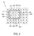
- FIG. 2 is a view similar to FIG. 1 , but illustrating a first block selected from the pattern according to a preferred embodiment of a pixel compensation method of the present invention.
- FIG. 3 is a view similar to FIG. 2 , but illustrating a second block selected from the pattern according to the preferred embodiment.
- FIG. 1 is a fragmentary schematic view of a pattern 10 obtained by an image sensor when used in conjunction with a color filter array (CFA).
- the image sensor may be a complementary metal oxide semiconductor (CMOS) sensor or a charge coupled device (CCD) sensor.
- CMOS complementary metal oxide semiconductor
- CCD charge coupled device
- the CFA may be of the Bayer filter type.
- the pattern 10 includes a plurality of blue rows 1 , and a plurality of red rows 2 arranged alternatingly with the blue rows 1 .
- a plurality of blue pixels 11 and a plurality of blue-row green pixels 12 are alternatingly arranged, and within each of the red rows 2 , a plurality of red pixels 21 and a plurality of red-row green pixels 22 are alternatingly arranged.
- the blue pixels 11 and the red-row green pixels 22 are arranged alternatingly in columns, and the blue-row green pixels 12 and the red pixels 21 are arranged alternatingly in columns.
- the columns formed by the blue pixels 11 and the red-row green pixels 22 are alternatingly arranged with the columns formed by the blue-row green pixels 12 and the red pixels 21 .
- the blue pixels 11 , the red pixels 21 , the blue-row green pixels 12 , and the red-row green pixels 22 respectively exhibit different response intensities during operation of the image sensor.
- greater differences between the response intensities of the pixels in the blue rows 1 and the response intensities of the pixels in the red rows 2 may occur due to various factors, such as lighting, circuit design characteristics, color differences, lens characteristics of the image-capturing device, etc.
- non-uniform color is especially problematic when there is unevenness between the blue-row green pixels 12 and the red-row green pixels 22 .
- the pixel compensation method of the present invention is able to solve color non-uniformity problems caused by such factors.
- the present invention is not limited with respect to the pattern 10 obtained by the image sensor as described above. That is, the method of the present invention contemplates application to image sensors used in conjunction with various types of color filter arrays, and is not limited to application to image sensors using a Bayer filter.
- a pixel compensation method according to a preferred embodiment of the present invention will now be described with reference to FIGS. 2 and 3 .
- a first block 3 of a predetermined number of pixels is selected from the pattern 10 .
- the predetermined number of pixels of the first block 3 is less than a total number of pixels of the pixel pattern 10 .
- the first block 3 includes twelve pixels formed of three rows and four columns of pixels.
- the pixels of the first block 3 are respectively numbered using reference numerals 311 , 312 , 313 , 314 , 321 , 322 , 323 , 324 , 331 , 332 , 333 , and 334 .
- the pixels 311 , 313 , 331 , and 333 are blue pixels corresponding to the blue pixels 11 of FIG. 1 ; the pixels 322 and 324 are red pixels corresponding to the red pixels 21 of FIG. 1 ; the pixels 312 , 314 , 332 , and 334 are blue-row green pixels corresponding to the blue-row green pixels 12 of FIG. 1 ; and the pixels 321 and 323 are red-row green pixels corresponding to the red-row green pixels 22 of FIG. 1 .
- the pixels completely surrounded by the other pixels of the first block 3 are designated as pixels that are to undergo compensation (hereinafter referred to as “stand-by compensation pixels”).
- the pixels 322 and 323 are the stand-by compensation pixels of the first block 3 .
- the response intensities of the pixels of the first block 3 determine an area characteristic with respect to the particular area where the first block 3 is located.
- the area characteristic is used to determine whether or not the stand-by compensation pixels will undergo compensation.
- a first compensation value is set at zero, and compensation of the response intensities of the stand-by compensation pixels of the first block 3 is performed using the first compensation value. That is, when the first block 3 is in one of the above three “high” areas, effectively no compensation of the stand-by compensation pixels of the first block 3 is performed.
- the meanings of these response area terms will become evident from the explanation provided below.
- a second block 3 ′ is selected from the pattern 10 by, for example, shifting the first block 3 to the right by two pixels, and stand-by compensation pixels of the second block 3 ′ are designated (i.e., pixels 322 ′ and 323 ′). Compensation of the stand-by compensation pixels of the second block 3 ′ is then performed, where effectively no compensation is performed if it is determined that the second block 3 ′ is in a high frequency response area, a relatively high frequency response area, or an extremely high frequency response area.
- the following are the steps involved in determining the response area where a selected block is positioned.
- the first block 3 of FIG. 2 is used as an example.
- Step 1 it is determined if the first block 3 is in a high frequency response area or a flat response area.
- the sub-steps involved in Step 1 are described below.
- a first threshold value is obtained.
- the first threshold value is a predetermined value.
- the first block 3 is determined to be in a high frequency response area. If this condition is not met, i.e., the differences in the response intensities of all pairs of identically colored pixels of the first block 3 are smaller than the first threshold value, it is determined that the first block 3 is in a flat response area.
- the differences in response intensities between pairs of the blue pixels 311 , 313 , 331 , and 333 are calculated, e.g., the differences in response intensities between the pixels 311 and 313 , the pixels 313 and 333 , the pixels 333 and 331 , and the pixels 331 and 311 are calculated; the difference in response intensities between the red pixels 322 and 324 is calculated; the differences in response intensities between pairs of the blue-row green pixels 312 , 314 , 332 , 334 are calculated, e.g., the differences in response intensities between the pixels 312 and 314 , the pixels 314 and 334 , the pixels 334 and 332 , and the pixels 332 and 312 are calculated; and the difference in response intensities between the red-row green pixels 321 and 323 is calculated.
- the first block 3 In determining the differences in response intensities between these pixels, if any one of the differences is greater than or equal to the first threshold value, it is determined that the first block 3 is in a high frequency response area, in which case the first compensation value is set at zero. Otherwise, it is determined that the first block 3 is in a flat response area.
- Step 1 can ensure that pixels are not erroneously compensated.
- Step 2 if it is determined that the first block 3 is in a flat response area, it is then determined if the first block 3 is in a relatively high frequency response area or a relatively flat response area.
- the sub-steps involved in Step 2 are described below.
- a second threshold value is obtained.
- the difference in response intensities of identically colored pixels in any two rows and in the same column of the first block 3 is greater than the second threshold value, and optionally also has the same gradient, for example, the response intensities of the pixels in these rows are all larger or smaller than the response intensities of identically colored pixels in another row and in the same column, it is determined that the first block 3 is in a relatively high frequency response area. If, on the other hand, the difference in response intensities of identically colored pixels in any two rows and in the same column of the first block 3 is smaller than or equal to the second threshold value, it is determined that the first block 3 is in a relatively flat response area.
- the differences in response intensities between the blue pixels 311 , 313 , 331 , 333 of the same row but different columns are calculated, namely, the differences in response intensities between the pixels 311 and 313 , and between the pixels 331 and 333 are calculated; the differences in response intensities between the blue-row green pixels 312 , 314 , 332 , 334 of the same row but different columns are calculated, namely, the differences in response intensities between the pixels 312 and 314 , and between the pixels 332 and 334 are calculated. If any one of these differences in response intensities is greater than the second threshold value, it is determined that the first block 3 is in a relatively high frequency response area, and the first compensation value is set at zero. Otherwise, it is determined that the first block 3 is in a relatively flat response area.
- Step 3 if it is determined that the first block 3 is in a relatively flat response area, then it is determined if the first block 3 is in an extremely high frequency response area or an extremely flat response area.
- the sub-steps associated with Step 3 will be described below.
- a predetermined third threshold value is obtained.
- the first block 3 when a difference between (a) an average value of the response intensities of four pixels of the same color and adjacent to one of the stand-by compensation pixels, and (b) the response intensity of the stand-by compensation pixel is greater than or equal to the third threshold value, it is determined that the first block 3 is in an extremely high frequency response area. Otherwise, it is determined that the first block 3 is in an extremely flat response area.
- the green pixels adjacent to the stand-by compensation pixel 323 i.e., the pixels 312 , 314 , 334 , 332 are selected, and an average value of their response intensities is obtained and compared with the response intensity of this particular stand-by compensation pixel 323 .
- the third threshold value it is determined that the first block 3 is in an extremely high frequency response area, and the first compensation value is set at zero. Otherwise (i.e., this difference is less than the third threshold value), it is determined that the first block 3 is in an extremely flat response area.
- the present invention further includes step 1 - 1 in which a contrast area where the first block 3 is located is determined based on the response intensities of all the pixels of the first block 3 .
- the second threshold value is then established according to the contrast area where the first block 3 is located, thereby resulting in more efficient and accurate removal of factors causing erroneous compensation.
- step 1 - 1 of determining the contrast area where the first block 3 is located is performed subsequent to step 1 of determining if the first block 3 is in a high frequency response area, and prior to step 2 of determining if the first block 3 is in a relatively high frequency response area. Step 1 - 1 is described in more detail below.
- the contrast area where the first block 3 is positioned is determined according to the response intensities of all the pixels of the first block 3 considered individually.
- the response intensity of each of the pixels 311 , 312 , 313 , 314 , 321 , 322 , 323 , 324 , 331 , 332 , 333 , 334 of the first block 3 is smaller than the first contrast threshold value, it is determined that the first block 3 is in a first contrast area.
- the response intensity of any one of the pixels 311 , 312 , 313 , 314 , 321 , 322 , 323 , 324 , 331 , 332 , 333 , 334 of the first block 3 is greater than or equal to the first contrast threshold value and smaller than the second contrast threshold value, it is determined that the first block 3 is in a second contrast area.
- the response intensity of each of the pixels 311 , 312 , 313 , 314 , 321 , 322 , 323 , 324 , 331 , 332 , 333 , 334 of the first block 3 is greater than or equal to the second contrast threshold value and smaller than the third contrast threshold value, it is determined that the first block 3 is in a third contrast area.
- the obtained second threshold value has different predetermined values according to the contrast area where the first block 3 is located.
- the value of the second threshold value corresponding to the first contrast area is smaller than the value of the second threshold value corresponding to the second contrast area
- the value of the second threshold value corresponding to the second contrast area is smaller than the value of the third threshold value corresponding to the third contrast area. Because the response intensities (brightnesses) of the pixels of the first block 3 are all different, the differences between the response intensities of the pixels are also all different. Therefore, in step 2 , the determination as to whether the first block 3 is in a relatively high frequency response area or a relatively flat response area is made based on the second threshold value, which is obtained differently for the different contrast areas, thereby further enhancing compensation accuracy.
- the first block 3 is in a high frequency response area, a relatively high frequency response area, or an extremely high frequency response area, and effectively no compensation is performed when the first block 3 is in one of these areas.
- a subsequent second block 3 ′ is selected.
- compensation is performed. That is, only when the first block 3 is in an extremely flat response area is compensation of the stand-by compensation pixels 322 and 323 of the first block 3 performed.
- the first compensation value is determined.
- the first compensation value is a difference between the response intensity of one of the stand-by compensation pixels and an average value of response intensities of identically colored pixels of the first block 3 adjacent to the one of the stand-by compensation pixels.
- the first compensation value is used to adjust the response intensities of both of the stand-by compensation pixels.
- an average value of the response intensities of the blue-row green pixels 312 , 314 , 334 , 332 is obtained, and a difference between this average value and the response intensity of the stand-by compensation pixel 323 is determined.
- the first compensation value is determined according to this difference, and compensation of both of the stand-by compensation pixels 322 and 323 is performed using the first compensation value thus obtained.
- a subsequent block i.e., the second block 3 ′
- a subsequent block is selected from the pattern 10 , after which processes similar to those performed with respect to the first block 3 are performed. That is, in the preferred embodiment, a second compensation value is obtained, and compensation of the stand-by compensation pixels 322 ′ and 323 ′ of the second block 3 ′ is performed according to both this second compensation value and the first compensation value of the first block 3 .
- Selection and compensation of blocks from the pattern 10 are continued in this manner until compensation of all the pixels in a particular set of rows has been performed, after which a new block is selected by, for example, shifting the present block downwardly by two rows and back to the start of a new set of rows. The shifting process along the new set of rows is then repeated. This process is continued until compensation of all the pixels in the pattern 10 has been performed. With compensation thus performed, the newly obtained pattern is one having color evenness.
- the compensation value obtained for the previously selected block may also be referenced to perform compensation as described above.
- its compensation value is equal to the sum of the first compensation value times a weighted value and the second compensation value times another weighted value, and the compensation value thus obtained is used to perform compensation of the pixels 322 ′ and 323 ′.
- the present invention uses a difference in response intensities between stand-by compensation pixels and pixels adjacent thereto, such that color uniformity may be realized.
- the area of location of the stand-by compensation pixels it is possible to eliminate compensation errors.
- different threshold values are given to contrast areas of different brightness levels to determine whether or not to perform compensation, thereby further enhancing precision.
- dynamically adjusting the compensation value each time compensation of the stand-by compensation pixels is performed even greater compensation precision may be realized.
Landscapes
- Engineering & Computer Science (AREA)
- Multimedia (AREA)
- Signal Processing (AREA)
- Color Television Image Signal Generators (AREA)
Abstract
Description
Claims (14)
Applications Claiming Priority (3)
| Application Number | Priority Date | Filing Date | Title |
|---|---|---|---|
| TW094117650A TWI260918B (en) | 2005-05-30 | 2005-05-30 | Pixel compensation method for an image sensor |
| TW94117650A | 2005-05-30 | ||
| TW094117650 | 2005-05-30 |
Publications (2)
| Publication Number | Publication Date |
|---|---|
| US20060268134A1 US20060268134A1 (en) | 2006-11-30 |
| US7916790B2 true US7916790B2 (en) | 2011-03-29 |
Family
ID=37462866
Family Applications (1)
| Application Number | Title | Priority Date | Filing Date |
|---|---|---|---|
| US11/420,612 Expired - Fee Related US7916790B2 (en) | 2005-05-30 | 2006-05-26 | Pixel compensation method for an image sensor |
Country Status (2)
| Country | Link |
|---|---|
| US (1) | US7916790B2 (en) |
| TW (1) | TWI260918B (en) |
Cited By (1)
| Publication number | Priority date | Publication date | Assignee | Title |
|---|---|---|---|---|
| US20110007102A1 (en) * | 2009-07-10 | 2011-01-13 | Casio Computer Co., Ltd. | Pixel drive apparatus, light-emitting apparatus and drive control method for light-emitting apparatus |
Families Citing this family (8)
| Publication number | Priority date | Publication date | Assignee | Title |
|---|---|---|---|---|
| US7907791B2 (en) * | 2006-11-27 | 2011-03-15 | Tessera International, Inc. | Processing of mosaic images |
| TWI449027B (en) * | 2011-08-30 | 2014-08-11 | Novatek Microelectronics Corp | Adaptive pixel compensation method |
| US9077943B2 (en) * | 2012-05-31 | 2015-07-07 | Apple Inc. | Local image statistics collection |
| KR102019186B1 (en) | 2012-08-16 | 2019-09-06 | 엘지이노텍 주식회사 | Image sensor and camera apparatus having the same |
| JP5830186B2 (en) * | 2013-02-05 | 2015-12-09 | 富士フイルム株式会社 | Image processing apparatus, imaging apparatus, image processing method, and program |
| US20140313217A1 (en) * | 2013-04-22 | 2014-10-23 | Broadcom Corporation | Display calibration |
| CN104299585B (en) * | 2014-10-14 | 2017-01-25 | 京东方科技集团股份有限公司 | Method for improving color errors, color error adjustment structure and display device |
| KR102610671B1 (en) * | 2019-10-02 | 2023-12-06 | 한화비전 주식회사 | Apparatus for interpolation color, and method therof |
Citations (6)
| Publication number | Priority date | Publication date | Assignee | Title |
|---|---|---|---|---|
| US6122004A (en) * | 1995-12-28 | 2000-09-19 | Samsung Electronics Co., Ltd. | Image stabilizing circuit for a camcorder |
| US6370330B2 (en) * | 1988-03-10 | 2002-04-09 | Canon Kabushiki Kaisha | Image shake detecting device |
| US6434276B2 (en) * | 1997-09-30 | 2002-08-13 | Sharp Kabushiki Kaisha | Image synthesis and communication apparatus |
| US20050237433A1 (en) * | 1999-07-30 | 2005-10-27 | Roy Van Dijk | System and method for motion compensation of image planes in color sequential displays |
| US7218675B1 (en) * | 1991-06-24 | 2007-05-15 | Canon Kabushiki Kaisha | Signal processing device |
| US7646891B2 (en) * | 2002-12-26 | 2010-01-12 | Mitshubishi Denki Kabushiki Kaisha | Image processor |
-
2005
- 2005-05-30 TW TW094117650A patent/TWI260918B/en not_active IP Right Cessation
-
2006
- 2006-05-26 US US11/420,612 patent/US7916790B2/en not_active Expired - Fee Related
Patent Citations (6)
| Publication number | Priority date | Publication date | Assignee | Title |
|---|---|---|---|---|
| US6370330B2 (en) * | 1988-03-10 | 2002-04-09 | Canon Kabushiki Kaisha | Image shake detecting device |
| US7218675B1 (en) * | 1991-06-24 | 2007-05-15 | Canon Kabushiki Kaisha | Signal processing device |
| US6122004A (en) * | 1995-12-28 | 2000-09-19 | Samsung Electronics Co., Ltd. | Image stabilizing circuit for a camcorder |
| US6434276B2 (en) * | 1997-09-30 | 2002-08-13 | Sharp Kabushiki Kaisha | Image synthesis and communication apparatus |
| US20050237433A1 (en) * | 1999-07-30 | 2005-10-27 | Roy Van Dijk | System and method for motion compensation of image planes in color sequential displays |
| US7646891B2 (en) * | 2002-12-26 | 2010-01-12 | Mitshubishi Denki Kabushiki Kaisha | Image processor |
Cited By (1)
| Publication number | Priority date | Publication date | Assignee | Title |
|---|---|---|---|---|
| US20110007102A1 (en) * | 2009-07-10 | 2011-01-13 | Casio Computer Co., Ltd. | Pixel drive apparatus, light-emitting apparatus and drive control method for light-emitting apparatus |
Also Published As
| Publication number | Publication date |
|---|---|
| TWI260918B (en) | 2006-08-21 |
| TW200642447A (en) | 2006-12-01 |
| US20060268134A1 (en) | 2006-11-30 |
Similar Documents
| Publication | Publication Date | Title |
|---|---|---|
| US7916790B2 (en) | Pixel compensation method for an image sensor | |
| CN1988673B (en) | Image processing circuit and image processing method | |
| US8817135B2 (en) | Correction of cluster defects in imagers | |
| EP1389771B1 (en) | Digital image system and method for combining demosaicing and bad pixel correction | |
| US8593548B2 (en) | Apparataus and method of automatic color shading removal in CMOS image sensors | |
| US5990950A (en) | Method and system for color filter array multifactor interpolation | |
| US7580070B2 (en) | System and method for roll-off correction in image processing | |
| US8218037B2 (en) | Techniques of modifying image field data by extrapolation | |
| RU2556022C2 (en) | Colour image forming apparatus | |
| KR100791375B1 (en) | Color correction device and method | |
| RU2548567C1 (en) | Colour image forming element | |
| US7683948B2 (en) | System and method for bad pixel replacement in image processing | |
| US7471820B2 (en) | Correction method for defects in imagers | |
| US20110102624A1 (en) | Pixel defect correction device, imaging apparatus, pixel defect correction method, and program | |
| EP3328080B1 (en) | Image processing method and imaging apparatus | |
| KR20080078044A (en) | Method and apparatus for reducing image noise | |
| CN108418997B (en) | Method for removing image moire | |
| TWI449027B (en) | Adaptive pixel compensation method | |
| TW201600835A (en) | Luminance measurement method, luminance measurement device, and image quality adjustment technique using the method and device | |
| CN112185301B (en) | Display device correction method and device and processor | |
| CN117471730A (en) | Method and device for detecting uneven brightness of display panel | |
| US7027091B1 (en) | Detection of color filter array alignment in image sensors | |
| US20040201758A1 (en) | Defective pixel correction device | |
| US20070097237A1 (en) | Method and apparatus of defective pixel correction for a solid-state imaging device | |
| US8036483B2 (en) | Couplet correction in image sensors |
Legal Events
| Date | Code | Title | Description |
|---|---|---|---|
| AS | Assignment |
Owner name: PIXART IMAGING INC., TAIWAN Free format text: ASSIGNMENT OF ASSIGNORS INTEREST;ASSIGNORS:CHEN, MEI-JU;CHAO, TZU-YI;REEL/FRAME:017837/0642;SIGNING DATES FROM 20060511 TO 20060515 Owner name: PIXART IMAGING INC., TAIWAN Free format text: ASSIGNMENT OF ASSIGNORS INTEREST;ASSIGNORS:CHEN, MEI-JU;CHAO, TZU-YI;SIGNING DATES FROM 20060511 TO 20060515;REEL/FRAME:017837/0642 |
|
| STCF | Information on status: patent grant |
Free format text: PATENTED CASE |
|
| FPAY | Fee payment |
Year of fee payment: 4 |
|
| FEPP | Fee payment procedure |
Free format text: ENTITY STATUS SET TO UNDISCOUNTED (ORIGINAL EVENT CODE: BIG.) |
|
| MAFP | Maintenance fee payment |
Free format text: PAYMENT OF MAINTENANCE FEE, 8TH YEAR, LARGE ENTITY (ORIGINAL EVENT CODE: M1552); ENTITY STATUS OF PATENT OWNER: LARGE ENTITY Year of fee payment: 8 |
|
| FEPP | Fee payment procedure |
Free format text: MAINTENANCE FEE REMINDER MAILED (ORIGINAL EVENT CODE: REM.); ENTITY STATUS OF PATENT OWNER: LARGE ENTITY |
|
| LAPS | Lapse for failure to pay maintenance fees |
Free format text: PATENT EXPIRED FOR FAILURE TO PAY MAINTENANCE FEES (ORIGINAL EVENT CODE: EXP.); ENTITY STATUS OF PATENT OWNER: LARGE ENTITY |
|
| STCH | Information on status: patent discontinuation |
Free format text: PATENT EXPIRED DUE TO NONPAYMENT OF MAINTENANCE FEES UNDER 37 CFR 1.362 |
|
| FP | Lapsed due to failure to pay maintenance fee |
Effective date: 20230329 |