US7914309B2 - Electrical connector comprising a mat seal and a ramp system for compressing the mat seal - Google Patents
Electrical connector comprising a mat seal and a ramp system for compressing the mat seal Download PDFInfo
- Publication number
- US7914309B2 US7914309B2 US12/450,261 US45026107A US7914309B2 US 7914309 B2 US7914309 B2 US 7914309B2 US 45026107 A US45026107 A US 45026107A US 7914309 B2 US7914309 B2 US 7914309B2
- Authority
- US
- United States
- Prior art keywords
- mat seal
- electrical connector
- grid
- housing
- rear grid
- Prior art date
- Legal status (The legal status is an assumption and is not a legal conclusion. Google has not performed a legal analysis and makes no representation as to the accuracy of the status listed.)
- Active
Links
Images


Classifications
-
- H—ELECTRICITY
- H01—ELECTRIC ELEMENTS
- H01R—ELECTRICALLY-CONDUCTIVE CONNECTIONS; STRUCTURAL ASSOCIATIONS OF A PLURALITY OF MUTUALLY-INSULATED ELECTRICAL CONNECTING ELEMENTS; COUPLING DEVICES; CURRENT COLLECTORS
- H01R13/00—Details of coupling devices of the kinds covered by groups H01R12/70 or H01R24/00 - H01R33/00
- H01R13/46—Bases; Cases
- H01R13/52—Dustproof, splashproof, drip-proof, waterproof, or flameproof cases
- H01R13/5213—Covers
-
- H—ELECTRICITY
- H01—ELECTRIC ELEMENTS
- H01R—ELECTRICALLY-CONDUCTIVE CONNECTIONS; STRUCTURAL ASSOCIATIONS OF A PLURALITY OF MUTUALLY-INSULATED ELECTRICAL CONNECTING ELEMENTS; COUPLING DEVICES; CURRENT COLLECTORS
- H01R13/00—Details of coupling devices of the kinds covered by groups H01R12/70 or H01R24/00 - H01R33/00
- H01R13/46—Bases; Cases
- H01R13/52—Dustproof, splashproof, drip-proof, waterproof, or flameproof cases
- H01R13/5205—Sealing means between cable and housing, e.g. grommet
- H01R13/5208—Sealing means between cable and housing, e.g. grommet having at least two cable receiving openings
-
- H—ELECTRICITY
- H01—ELECTRIC ELEMENTS
- H01R—ELECTRICALLY-CONDUCTIVE CONNECTIONS; STRUCTURAL ASSOCIATIONS OF A PLURALITY OF MUTUALLY-INSULATED ELECTRICAL CONNECTING ELEMENTS; COUPLING DEVICES; CURRENT COLLECTORS
- H01R13/00—Details of coupling devices of the kinds covered by groups H01R12/70 or H01R24/00 - H01R33/00
- H01R13/62—Means for facilitating engagement or disengagement of coupling parts or for holding them in engagement
- H01R13/629—Additional means for facilitating engagement or disengagement of coupling parts, e.g. aligning or guiding means, levers, gas pressure electrical locking indicators, manufacturing tolerances
- H01R13/62933—Comprising exclusively pivoting lever
- H01R13/62938—Pivoting lever comprising own camming means
Definitions
- the present invention relates to electrical connectors with a mat seal.
- EP-A1-1 296 415 describes an electrical connector of the type comprising:
- the insulative housing comprises a housing body and a contact carrier, able to slide on each other.
- the known electrical connector For assembling the known electrical connector, cables are introduced through the mat seal for accommodating the terminals in the accommodating chambers arranged in the contact carrier.
- the known electrical connector comprises rotatory lever system for locking the connector to a counterpart connector.
- the lever system is arranged so that, when activated, it brings the housing body closer to the contact carrier. The housing body thus drags along the rear grid so that the rear grid compresses the mat seal.
- the invention proposes an electrical connector arranged so that an alternative assembling is possible.
- an electrical connector of the previous type comprising:
- the mounting of the mobile part automatically leads to the compressing of the mat seal. In this way, the sealing of the cables occurs when the connector is assembled.
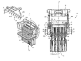
- FIG. 1 is tri-dimensional view of an electrical connector according to the invention, before being assembled.
- FIG. 2 is a tri-dimensional cross-sectional view along the II plane of FIG. 1 , before the electrical connector is assembled.
- FIGS. 3 and 4 are cross-sectional views along the III, IV plane of FIG. 1 , the electrical connector being assembled.
- the electrical connector 10 is a male connector of a type used in automotive applications, intended to mate with a counterpart female connector.
- the electrical connector according to the invention could be a female connector intended to mate with a counterpart male connector.
- the electrical connector 10 comprises an insulative housing 12 , usually made of a plastic material.
- the insulative housing 12 is essentially constituted of a parallelepiped having a front face 14 for being mated with a counterpart female electrical connector (not shown), and a rear face 16 (visible on FIGS. 2 , 3 and 4 ) for inserting cable terminals (not shown).
- a plurality of accommodating chambers 18 are formed in the insulative housing 12 .
- Each accommodating chamber 18 opens, first on the rear face 16 for inserting a respective cable terminal, and second on the front face 14 so that the respective cable terminal accommodated in the accommodating chamber 18 can be connected to a counterpart terminal (not shown), of the counterpart connector.
- a rear skirt 20 extends rearward with respect to the rear face 16 .
- the rear skirt 20 is made integral with the housing 12 , in a single molding process.
- the rear skirt 20 defines a substantially rectangular rear aperture 22 , located opposite the insulative housing 12 .
- the rear skirt 20 is provided with two ribs 24 , located at two opposite sides of the rear aperture 22 .
- the ribs 24 extend transversally relative to the XX′ direction. Each rib 24 forms a guide rail for a rear cap 26 .
- the ribs 24 project perpendicularly to the XX′ axis, i.e. toward the sides of the electrical connector, so as to form a stop for the rear cap 26 in the XX′ direction.
- the rear skirt 20 is also provided with complementary ribs 25 which also extend transversally relative to the XX′ direction, but project along the XX′ direction, toward the rear face 16 of the connector, so that the complementary ribs 25 form a lateral stop for the rear cap 26 , preventing lateral displacement of the rear cap 26 .
- the ribs 24 and the complementary ribs 25 are alternatively discontinuous. They complement each other, i.e. the discontinuity of the rib 24 corresponds to the presence of the rib 25 . This permits their molding.
- the rear cap 26 is intended to be mounted on the rear skirt 20 so as to cover the rear aperture 22 .
- the rear cap 26 comprises two lateral walls 26 A provided with respective grooves 27 able to cooperate with the ribs 24 of the rear skirt 20 .
- the rear cap 26 is opened on a side between the lateral walls 26 A, so as to define a lateral cable entrance 28 .
- a mat seal 30 made of elastomer material, is disposed in the rear skirt 20 , against the rear face 16 .
- the mat seal 30 is provided with a plurality of cable passages 32 facing the accommodating chambers 18 .
- a clearance is provided laterally between the mat seal 30 and the rear skirt 20 .
- the clearance between the rear skirt 20 and the mat seal 30 is from 0.15 to 0.4 millimeters.
- the clearance insures that no compression is induced on the mat seal 30 by the rear skirt 20 .
- the cables may be inserted through the mat seal without deteriorating the mat seal 30 , since the mat seal is not compressed.
- the clearance that is present when the mat seal is not compressed allows the enlargement of the passages of the mat seal, when the cables are introduced.
- a rear grid 34 is also disposed in the rear skirt 20 , against the mat seal 30 .
- the rear grid 34 is provided with a plurality of cable passages 36 facing the cable passages of the mat seal 30 .
- the rear grid 34 is able to slide along the XX′ axis in the rear skirt 20 , so as to move forward towards the insulative housing, and in particular towards the rear face 16 .
- each cable thus makes a bend inside the rear cap 26 , before passing through the rear grid 34 then the mat seal 30 , in order to reach an accommodating chamber 18 , in which the terminal of the cable lies.
- the rear grid 34 comprises two opposite peripheral latches 36 .
- Each latch 36 is intended to be received in a corresponding recess 38 arranged on the inner side 20 A of the rear skirt 20 .
- the recesses 38 form a stop for maintaining the rear grid 34 in a pre-locking position against the mat seal 30 , via their cooperation with the latches 36 .
- the pre-locking position is depicted on FIGS. 1 and 2 . More precisely, the recesses 38 and the latches 36 prevent the rear grid 34 from moving rearward in the rear skirt 20 , away from the rear face 20 .
- the recesses 38 are placed in the XX′ direction so that the rear grid 34 in the pre-locking position does not compress the mat seal 30 .
- the cable passages 32 of the mat seal 30 are thus radially uncompressed, which allow an easy insertion/removing of the cables. Furthermore, the easy insertion/removing prevents deterioration of the mat seal.
- the rear grid 34 further comprises two opposite rear flanges 40 .
- Each flange 40 projects rearward with respect to the rear grid 34 , along the inner side 20 A of the rear skirt 20 .
- the flanges 40 are chamfered at each of their ends, so as to form ramps 42 , see FIGS. 1 and 2 .
- the flanges 40 are thus symmetrical.
- the flanges 40 are preferably made integral and moulded in a single process with the rear grid. The flanges 40 are thus fixed to the rear grid.
- the lateral walls 26 A are provided with inner ribs 44 projecting towards the inside of the rear cap 26 .
- the inner ribs 44 hit the ramps 42 , which causes the rear grid 34 to slide along the XX′ direction, toward the mat seal in the rear skirt 20 , thus longitudinally compressing the mat seal 20 against the rear face 16 of the insulative housing 12 until an end position is attained. Since the flanges 30 are symmetrical, the rear cap 26 can be mounted from each extremity of the flanges.
- the two flanges 40 can be replaced by a similar but unique flange projecting rearward from a medium line of the rear grid 24 situated between two rows of cable passages and the ribs 44 being replaced by a unique rib projecting toward the grid from a top of the cover 24 .
- the height of the flange 40 can be between 3 to 10 mm, preferentially between 4 to 5 mm.
- the rear cap is locked by using clipping means, such as latches provided on the rear cap, so as to enter corresponding holes provided in the housing 12 .
- FIGS. 3 and 4 showing the end position, the compression is maintained while the rear cap 26 covers the rear aperture 22 by the lateral walls 26 A of the rear cap 26 forming a stop for the flanges 40 , preventing a rear ward sliding of the rear grid 34 .
- the mat seal is laterally confined by the rear skirt 20 , so that the mat seal first extend against the rear skirt, i.e. until the clearance is filled up, then the passages shrink.
- the assembling of the connector 10 is easy, because the mounting of the rear cap 26 automatically induces the sealing of the cables pressing through the mat seal 20 .
- the disassembling of the rear cap 26 will let the rear grid 24 free of moving rearward, thus allowing a spring back of the mat seal 20 .
- the cables may be removed without deteriorating the mat seal 20 , which then can be re-used.
- the electrical connector could only have one flange.
- the flanges could be carried by the rear cap, and/or have different form.
- the guide rails could be formed by grooves instead of ribs.
- the lateral walls of the rear cap would be provided with corresponding ribs.
Landscapes
- Connector Housings Or Holding Contact Members (AREA)
- Mattresses And Other Support Structures For Chairs And Beds (AREA)
- Resistance Heating (AREA)
Abstract
Description
-
- an insulative housing having:
- a front face for being mated with a counterpart electrical connector, and
- a rear face for inserting cable terminals,
- a plurality of terminal accommodating chambers, which each open on the rear face for inserting of a respective cable terminal, and on the front face so that the respective cable terminal accommodated in the accommodating chamber can be connected to a counterpart terminal of the counterpart connector,
- a rear skirt extending rearward with respect to the rear face,
- a mat seal disposed in the rear skirt against the rear face, and having a plurality of cable passages facing the accommodating chambers,
- a rear grid, disposed in the rear skirt, against the mat seal, and having a plurality of cable passages facing the cable passages of the mat seal.
- an insulative housing having:
-
- a mobile part,
- a guide rail fixed to the housing, the guide rail being transverse to the front-rear direction, for transversally guiding the mobile part,
- a ramp system such that, when the mobile part is guided by the guide rail, the ramp system pushes the rear grid against the mat seal so as to compress the mat seal.
Claims (14)
Applications Claiming Priority (1)
| Application Number | Priority Date | Filing Date | Title |
|---|---|---|---|
| PCT/IB2007/051436 WO2008114100A2 (en) | 2007-03-20 | 2007-03-20 | Electrical connector comprising a mat seal |
Publications (2)
| Publication Number | Publication Date |
|---|---|
| US20100075524A1 US20100075524A1 (en) | 2010-03-25 |
| US7914309B2 true US7914309B2 (en) | 2011-03-29 |
Family
ID=39766549
Family Applications (1)
| Application Number | Title | Priority Date | Filing Date |
|---|---|---|---|
| US12/450,261 Active US7914309B2 (en) | 2007-03-20 | 2007-03-20 | Electrical connector comprising a mat seal and a ramp system for compressing the mat seal |
Country Status (7)
| Country | Link |
|---|---|
| US (1) | US7914309B2 (en) |
| EP (1) | EP2140522B1 (en) |
| CN (1) | CN101542846B (en) |
| AT (1) | ATE491247T1 (en) |
| DE (1) | DE602007011116D1 (en) |
| PL (1) | PL2140522T3 (en) |
| WO (1) | WO2008114100A2 (en) |
Cited By (1)
| Publication number | Priority date | Publication date | Assignee | Title |
|---|---|---|---|---|
| US11121499B2 (en) * | 2017-04-19 | 2021-09-14 | Jaguar Land Rover Limited | Cover system and method |
Families Citing this family (13)
| Publication number | Priority date | Publication date | Assignee | Title |
|---|---|---|---|---|
| US7914309B2 (en) * | 2007-03-20 | 2011-03-29 | Fci | Electrical connector comprising a mat seal and a ramp system for compressing the mat seal |
| EP2476166B1 (en) * | 2009-09-11 | 2017-04-26 | Delphi International Operations Luxembourg S.à r.l. | Mat sealing joint, electrical connector, and method of manufacture |
| DE102011004347A1 (en) * | 2011-02-17 | 2012-08-23 | Tyco Electronics Amp Gmbh | Electrical connector and plug-in system |
| ITTO20120905A1 (en) * | 2012-10-16 | 2014-04-17 | Tyco Electronics Amp Italia Srl | ELECTRIC CONNECTOR WITH SEALING ELEMENT AND PROCEDURE FOR ASSEMBLY |
| FR3015766A1 (en) * | 2013-12-19 | 2015-06-26 | Delphi Int Operations Luxembourg Sarl | SEALED FUSE HOLDER |
| JP2017228442A (en) * | 2016-06-23 | 2017-12-28 | 日本圧着端子製造株式会社 | connector |
| JP1595977S (en) * | 2017-08-01 | 2018-01-29 | ||
| CN108832348B (en) * | 2018-06-26 | 2024-01-30 | 合兴汽车电子(太仓)有限公司 | Connector with a plurality of connectors |
| JP7051248B2 (en) * | 2019-10-16 | 2022-04-11 | 矢崎総業株式会社 | connector |
| JP1730745S (en) * | 2022-05-20 | 2022-11-28 | connector | |
| JP1730746S (en) * | 2022-05-20 | 2022-11-28 | connector | |
| JP1742941S (en) * | 2022-09-06 | 2023-04-26 | connector | |
| JP7764993B2 (en) * | 2022-11-29 | 2025-11-06 | ティーイー コネクティビティ インディア プライベート リミテッド | Connector with Perimeter Seal Protection |
Citations (8)
| Publication number | Priority date | Publication date | Assignee | Title |
|---|---|---|---|---|
| US6071147A (en) | 1997-03-10 | 2000-06-06 | Yazak Corporation | Waterproof connector |
| US6116938A (en) * | 1997-08-28 | 2000-09-12 | The Whitaker Corporation | Low profile electrical connector |
| US6752659B2 (en) * | 2001-02-22 | 2004-06-22 | Yazaki Corporation | Waterproof connector |
| JP2005123102A (en) | 2003-10-20 | 2005-05-12 | Yazaki Corp | connector |
| US7056137B1 (en) * | 2005-02-28 | 2006-06-06 | Lear Corporation | Electrical connectors having a sealing element |
| US7354308B2 (en) * | 2005-08-03 | 2008-04-08 | Yazaki Corporation | Waterproof connector for flat cable |
| EP1926415A1 (en) | 2005-08-11 | 2008-06-04 | Otter Controls Limited | Scale detection on water heating elements |
| US20100075524A1 (en) * | 2007-03-20 | 2010-03-25 | Frederic Chazottes | Electrical connector comprising a mat seal |
Family Cites Families (1)
| Publication number | Priority date | Publication date | Assignee | Title |
|---|---|---|---|---|
| ITMI20050347A1 (en) * | 2005-03-07 | 2006-09-08 | Ilme Spa | ELECTRIC CONNECTOR ELEMENT FOR CONDUCTORS WITH CRIMPED CONTACTS |
-
2007
- 2007-03-20 US US12/450,261 patent/US7914309B2/en active Active
- 2007-03-20 PL PL07735569T patent/PL2140522T3/en unknown
- 2007-03-20 WO PCT/IB2007/051436 patent/WO2008114100A2/en not_active Ceased
- 2007-03-20 AT AT07735569T patent/ATE491247T1/en not_active IP Right Cessation
- 2007-03-20 DE DE602007011116T patent/DE602007011116D1/en active Active
- 2007-03-20 CN CN2007800430436A patent/CN101542846B/en active Active
- 2007-03-20 EP EP07735569A patent/EP2140522B1/en active Active
Patent Citations (8)
| Publication number | Priority date | Publication date | Assignee | Title |
|---|---|---|---|---|
| US6071147A (en) | 1997-03-10 | 2000-06-06 | Yazak Corporation | Waterproof connector |
| US6116938A (en) * | 1997-08-28 | 2000-09-12 | The Whitaker Corporation | Low profile electrical connector |
| US6752659B2 (en) * | 2001-02-22 | 2004-06-22 | Yazaki Corporation | Waterproof connector |
| JP2005123102A (en) | 2003-10-20 | 2005-05-12 | Yazaki Corp | connector |
| US7056137B1 (en) * | 2005-02-28 | 2006-06-06 | Lear Corporation | Electrical connectors having a sealing element |
| US7354308B2 (en) * | 2005-08-03 | 2008-04-08 | Yazaki Corporation | Waterproof connector for flat cable |
| EP1926415A1 (en) | 2005-08-11 | 2008-06-04 | Otter Controls Limited | Scale detection on water heating elements |
| US20100075524A1 (en) * | 2007-03-20 | 2010-03-25 | Frederic Chazottes | Electrical connector comprising a mat seal |
Cited By (1)
| Publication number | Priority date | Publication date | Assignee | Title |
|---|---|---|---|---|
| US11121499B2 (en) * | 2017-04-19 | 2021-09-14 | Jaguar Land Rover Limited | Cover system and method |
Also Published As
| Publication number | Publication date |
|---|---|
| WO2008114100A3 (en) | 2009-01-29 |
| CN101542846A (en) | 2009-09-23 |
| EP2140522A2 (en) | 2010-01-06 |
| DE602007011116D1 (en) | 2011-01-20 |
| PL2140522T3 (en) | 2011-05-31 |
| CN101542846B (en) | 2011-08-24 |
| ATE491247T1 (en) | 2010-12-15 |
| US20100075524A1 (en) | 2010-03-25 |
| EP2140522B1 (en) | 2010-12-08 |
| WO2008114100A2 (en) | 2008-09-25 |
Similar Documents
| Publication | Publication Date | Title |
|---|---|---|
| US7914309B2 (en) | Electrical connector comprising a mat seal and a ramp system for compressing the mat seal | |
| EP1211757B1 (en) | Elektrical connector | |
| US9666972B2 (en) | Electrical connector | |
| US8262410B2 (en) | Electrical connector | |
| US9368897B2 (en) | Electrical connector | |
| US7252547B2 (en) | Connector | |
| US7722381B2 (en) | Connector | |
| US8430689B2 (en) | Electrical connector | |
| US20100178791A1 (en) | Electrical Connector | |
| EP1990869A1 (en) | A connector and assembling method thereof | |
| CN101218714B (en) | Connector Assemblies with Terminal Position Assurance Devices | |
| US6568948B2 (en) | Connector | |
| CN102255174A (en) | Lever type electrical connector | |
| US6520788B2 (en) | Watertight connector and sealing member | |
| CN101779337B (en) | Electric connector | |
| EP3021423B1 (en) | Electrical connector | |
| US20100055954A1 (en) | Sealed electrical connector | |
| US9647378B1 (en) | Electrical connector | |
| US7033230B2 (en) | Connector | |
| JP4513677B2 (en) | Waterproof connector | |
| JP6015628B2 (en) | connector | |
| JP4035657B2 (en) | connector | |
| CN114824899A (en) | Connector with a locking member |
Legal Events
| Date | Code | Title | Description |
|---|---|---|---|
| AS | Assignment |
Owner name: FCI,FRANCE Free format text: ASSIGNMENT OF ASSIGNORS INTEREST;ASSIGNORS:CAMPFORT, CHRISTIAN;LEGUAY, THIERRY;AESCHBACHER, MICHEL;SIGNING DATES FROM 20090928 TO 20091002;REEL/FRAME:023531/0921 Owner name: FCI,FRANCE Free format text: ASSIGNMENT OF ASSIGNORS INTEREST;ASSIGNOR:CHAZOTTES, FREDERIC;REEL/FRAME:023531/0925 Effective date: 20081219 Owner name: FCI, FRANCE Free format text: ASSIGNMENT OF ASSIGNORS INTEREST;ASSIGNORS:CAMPFORT, CHRISTIAN;LEGUAY, THIERRY;AESCHBACHER, MICHEL;SIGNING DATES FROM 20090928 TO 20091002;REEL/FRAME:023531/0921 Owner name: FCI, FRANCE Free format text: ASSIGNMENT OF ASSIGNORS INTEREST;ASSIGNOR:CHAZOTTES, FREDERIC;REEL/FRAME:023531/0925 Effective date: 20081219 |
|
| STCF | Information on status: patent grant |
Free format text: PATENTED CASE |
|
| AS | Assignment |
Owner name: FCI AUTOMOTIVE HOLDING, FRANCE Free format text: ASSIGNMENT OF ASSIGNORS INTEREST;ASSIGNOR:FCI;REEL/FRAME:026307/0310 Effective date: 20110407 |
|
| AS | Assignment |
Owner name: DELPHI TECHNOLOGIES OPERATIONS LUXEMBOURG S.A.R.L. Free format text: ASSIGNMENT OF ASSIGNORS INTEREST;ASSIGNOR:FCI AUTOMOTIVE HOLDING SAS;REEL/FRAME:030302/0763 Effective date: 20130418 |
|
| AS | Assignment |
Owner name: DELPHI INTERNATIONAL OPERATIONS LUXEMBOURG, S.A.R. Free format text: CORRECTIVE ASSIGNMENT; REEL/FRAME: 030302/O763; CORRECTED ASSIGNEE;ASSIGNOR:FCI AUTOMOTIVE HOLDING SAS;REEL/FRAME:030353/0183 Effective date: 20130418 |
|
| FPAY | Fee payment |
Year of fee payment: 4 |
|
| AS | Assignment |
Owner name: APTIV TECHNOLOGIES LIMITED, BARBADOS Free format text: ASSIGNMENT OF ASSIGNORS INTEREST;ASSIGNOR:DELPHI INTERNATIONAL OPERATIONS LUXEMBOURG SARL;REEL/FRAME:047589/0181 Effective date: 20180101 |
|
| MAFP | Maintenance fee payment |
Free format text: PAYMENT OF MAINTENANCE FEE, 8TH YEAR, LARGE ENTITY (ORIGINAL EVENT CODE: M1552); ENTITY STATUS OF PATENT OWNER: LARGE ENTITY Year of fee payment: 8 |
|
| MAFP | Maintenance fee payment |
Free format text: PAYMENT OF MAINTENANCE FEE, 12TH YEAR, LARGE ENTITY (ORIGINAL EVENT CODE: M1553); ENTITY STATUS OF PATENT OWNER: LARGE ENTITY Year of fee payment: 12 |
|
| AS | Assignment |
Owner name: APTIV TECHNOLOGIES (2) S.A R.L., LUXEMBOURG Free format text: ENTITY CONVERSION;ASSIGNOR:APTIV TECHNOLOGIES LIMITED;REEL/FRAME:066746/0001 Effective date: 20230818 Owner name: APTIV MANUFACTURING MANAGEMENT SERVICES S.A R.L., LUXEMBOURG Free format text: MERGER;ASSIGNOR:APTIV TECHNOLOGIES (2) S.A R.L.;REEL/FRAME:066566/0173 Effective date: 20231005 Owner name: APTIV TECHNOLOGIES AG, SWITZERLAND Free format text: ASSIGNMENT OF ASSIGNORS INTEREST;ASSIGNOR:APTIV MANUFACTURING MANAGEMENT SERVICES S.A R.L.;REEL/FRAME:066551/0219 Effective date: 20231006 |