US791104A - Nut-lock washer. - Google Patents
Nut-lock washer. Download PDFInfo
- Publication number
- US791104A US791104A US16926103A US1903169261A US791104A US 791104 A US791104 A US 791104A US 16926103 A US16926103 A US 16926103A US 1903169261 A US1903169261 A US 1903169261A US 791104 A US791104 A US 791104A
- Authority
- US
- United States
- Prior art keywords
- nut
- washer
- lock washer
- bar
- bolts
- Prior art date
- Legal status (The legal status is an assumption and is not a legal conclusion. Google has not performed a legal analysis and makes no representation as to the accuracy of the status listed.)
- Expired - Lifetime
Links
- 238000005452 bending Methods 0.000 description 2
- 238000010276 construction Methods 0.000 description 2
- 210000000080 chela (arthropods) Anatomy 0.000 description 1
- 238000002788 crimping Methods 0.000 description 1
- 238000003780 insertion Methods 0.000 description 1
- 230000037431 insertion Effects 0.000 description 1
- 238000000034 method Methods 0.000 description 1
- 230000004048 modification Effects 0.000 description 1
- 238000012986 modification Methods 0.000 description 1
Images
Classifications
-
- F—MECHANICAL ENGINEERING; LIGHTING; HEATING; WEAPONS; BLASTING
- F16—ENGINEERING ELEMENTS AND UNITS; GENERAL MEASURES FOR PRODUCING AND MAINTAINING EFFECTIVE FUNCTIONING OF MACHINES OR INSTALLATIONS; THERMAL INSULATION IN GENERAL
- F16B—DEVICES FOR FASTENING OR SECURING CONSTRUCTIONAL ELEMENTS OR MACHINE PARTS TOGETHER, e.g. NAILS, BOLTS, CIRCLIPS, CLAMPS, CLIPS OR WEDGES; JOINTS OR JOINTING
- F16B39/00—Locking of screws, bolts or nuts
- F16B39/02—Locking of screws, bolts or nuts in which the locking takes place after screwing down
- F16B39/10—Locking of screws, bolts or nuts in which the locking takes place after screwing down by a plate, spring, wire or ring immovable with regard to the bolt or object and mainly perpendicular to the axis of the bolt
- F16B39/101—Locking of screws, bolts or nuts in which the locking takes place after screwing down by a plate, spring, wire or ring immovable with regard to the bolt or object and mainly perpendicular to the axis of the bolt with a plate, spring, wire or ring holding two or more nuts or bolt heads which are mainly in the same plane
-
- Y—GENERAL TAGGING OF NEW TECHNOLOGICAL DEVELOPMENTS; GENERAL TAGGING OF CROSS-SECTIONAL TECHNOLOGIES SPANNING OVER SEVERAL SECTIONS OF THE IPC; TECHNICAL SUBJECTS COVERED BY FORMER USPC CROSS-REFERENCE ART COLLECTIONS [XRACs] AND DIGESTS
- Y10—TECHNICAL SUBJECTS COVERED BY FORMER USPC
- Y10S—TECHNICAL SUBJECTS COVERED BY FORMER USPC CROSS-REFERENCE ART COLLECTIONS [XRACs] AND DIGESTS
- Y10S411/00—Expanded, threaded, driven, headed, tool-deformed, or locked-threaded fastener
- Y10S411/955—Locked bolthead or nut
- Y10S411/974—Side lock
- Y10S411/983—Inelastic tongue
Definitions
- This invention relates to devices employed for locking nuts upon bolts, more particularly the bolts of railway-rail joints, and has for its" object to simplify and improve devices of this character and produce a device which may be cheaply constructed, easily applied, and which will effectually hold the nut in whatever position it may be set and prevent its working loose, no matter how severe may be the jarring strains to which it will be subjected.
- the invention consists in certain novel features of construction, as hereinafter shown and described, and specified in the claim.
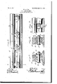
- Figure 1 is a side elevation of a railwayrail joint with the improvement applied.
- Fig. 2 is a transverse section on the line2 2 of Fig. 1.
- Fig. 3 is a detail view illustrating a modification in the construction.
- Fig. 4 is a transverse section on the line 4 4 of Fig. 3.
- the structure selected to illustrate the application of the improved device consists of Then when the nut is set up as tightly as required a properly-formed implement, such as a pair of pincers, will be inserted within the recess and the free edges of the washer-plates bent over into engagement with the nut, and thus effectually prevent its turning upon the washer-plate.
- a properly-formed implement such as a pair of pincers
- Two or more of the washer-plates may be connected by an integral lateral extension or bar 17 as in Fig. 1. in which instance said extension will serve as a common locking means for all of, the washers so connected to hold them against rotation,'or a lateral extension 18, as in Fig. 3, may be formed upon each washer-plate individually, in which instance said extension will engage the baseflange of the rail or other stationary portion of the member through which the bolt is passed.
- the washer-plates may be firmly locked to the nut and also to the body being held by the bolt and all rotative movement of the nut upon the bolt effectually prevented.
- the plates 16 may be provided with spaced radial clefts 19, if required, to facilitate the bending of-their margins into engagement with the nuts.
Description
- PATBNTED MAY'30,1905. I w. B. NBEL. v 4 NUT LOOK WASHER. H
UNITED STATES Patented May 30, 1905.
WILLIAM B. NEEL, OF WILSONVILLE, KENTUCKY.
L NUT-LOCK WASHER.
SPECIFICATION forming part of Letters Patent No. 791,104, dated May 53:0, 1905.
- Application filed August 12,1903. Serial No.169,261.
T0 aZZ whom it may concern:
Be it known thatI, WILLIAM B. NEEL, acitizen of the United States, residing at Wilsonville, in the county of Spencer and State of Kentucky, have invented a new and useful N ut-Lock Washer, of which the following is a specification. r
This invention relates to devices employed for locking nuts upon bolts, more particularly the bolts of railway-rail joints, and has for its" object to simplify and improve devices of this character and produce a device which may be cheaply constructed, easily applied, and which will effectually hold the nut in whatever position it may be set and prevent its working loose, no matter how severe may be the jarring strains to which it will be subjected.
The invention consists in certain novel features of construction, as hereinafter shown and described, and specified in the claim.
In the drawings, in which corresponding parts are denoted by like designating characters, Figure 1 is a side elevation of a railwayrail joint with the improvement applied. Fig. 2 is a transverse section on the line2 2 of Fig. 1. Fig. 3 is a detail view illustrating a modification in the construction. Fig. 4 is a transverse section on the line 4 4 of Fig. 3.
While I have shown the improved washer applied to a railway-rail joint, I do not Wish to be limited in any manner to the use of the device to any specific structure or locality, but reserve the right to its use for all purposes and in connection with all structures to.
which it is adapted.
The structure selected to illustrate the application of the improved device consists of Then when the nut is set up as tightly as required a properly-formed implement, such as a pair of pincers, will be inserted within the recess and the free edges of the washer-plates bent over into engagement with the nut, and thus effectually prevent its turning upon the washer-plate.
Two or more of the washer-plates may be connected by an integral lateral extension or bar 17 as in Fig. 1. in which instance said extension will serve as a common locking means for all of, the washers so connected to hold them against rotation,'or a lateral extension 18, as in Fig. 3, may be formed upon each washer-plate individually, in which instance said extension will engage the baseflange of the rail or other stationary portion of the member through which the bolt is passed. By this simple means the washer-plates may be firmly locked to the nut and also to the body being held by the bolt and all rotative movement of the nut upon the bolt effectually prevented.
I The plates 16 may be provided with spaced radial clefts 19, if required, to facilitate the bending of-their margins into engagement with the nuts. g
The crimping of the margins of the washerplates, whereby recesses are left between theadjacent faces of the washer and clamp plates, is an important feature of the invention, as by that means provision is made forthe ready insertion of the bending implement and obviates the necessity for providing a specifically-formed implement for that purpose, as any implement which may be forced into the recess will accomplish the work. Thus the completion of the locking process may be quickly and readily accomplished with the implement which may be most convenient. This is an important feature of the invention and adds materially to its efficiency and operativeness.
Having thus described my invention, what I claim is The combination with a body, of a plurality of bolts extending therethrough, nuts threaded on said bolts, a flat longitudinal bar having terminal and intermediate openings formed therein for the reception of said bolts and hav- 9 g ing its opposite ends at said openings terminating in spherical enlargements, the continuous marginal edges of which arecurved laterally beyond the general plane of the bar to form washers, said bar having its upper and lower edges at the intermediate openings extended laterally forming spaced projections, the marginal edges of which are curved both longitudinally and laterally, there being reversely-inclined incisions formed in the bar on each side of the intermediate openings and extended inwardly from the points of juncture of the longitudinally-eurved marginal edges of the lateral projections with said bar to thereby permit the washers to be'bent in- 5 wardly into engagement with the nuts on either side of the openings.
In testimony that I claim the foregoing as my own I have hereto ailixed my signature in the presence of two witnesses.
WILLIAM B. NEEL.
Witnesses;
JAMES S. MOMULLAN, W. M. CARDWELL.
Priority Applications (1)
| Application Number | Priority Date | Filing Date | Title |
|---|---|---|---|
| US16926103A US791104A (en) | 1903-08-12 | 1903-08-12 | Nut-lock washer. |
Applications Claiming Priority (1)
| Application Number | Priority Date | Filing Date | Title |
|---|---|---|---|
| US16926103A US791104A (en) | 1903-08-12 | 1903-08-12 | Nut-lock washer. |
Publications (1)
| Publication Number | Publication Date |
|---|---|
| US791104A true US791104A (en) | 1905-05-30 |
Family
ID=2859593
Family Applications (1)
| Application Number | Title | Priority Date | Filing Date |
|---|---|---|---|
| US16926103A Expired - Lifetime US791104A (en) | 1903-08-12 | 1903-08-12 | Nut-lock washer. |
Country Status (1)
| Country | Link |
|---|---|
| US (1) | US791104A (en) |
-
1903
- 1903-08-12 US US16926103A patent/US791104A/en not_active Expired - Lifetime
Similar Documents
| Publication | Publication Date | Title |
|---|---|---|
| US907473A (en) | Nut-lock. | |
| US791104A (en) | Nut-lock washer. | |
| US1302105A (en) | Nut-lock. | |
| US174175A (en) | Improvement in nut-locks | |
| US1086441A (en) | Fence-post. | |
| US733245A (en) | Nut-lock. | |
| US1056686A (en) | Nut-lock. | |
| US923264A (en) | Nut-lock. | |
| US1036991A (en) | Nut-lock. | |
| US848541A (en) | Nut-lock. | |
| US375711A (en) | John j | |
| US938932A (en) | Nut-lock. | |
| US680690A (en) | Nut-lock. | |
| US770325A (en) | Nut-lock. | |
| US285399A (en) | William b | |
| US838020A (en) | Nut-lock. | |
| US725245A (en) | Nut-lock. | |
| US470677A (en) | Nut-lock | |
| US577174A (en) | Nut-lock | |
| US282927A (en) | Fabius bobbins | |
| US783017A (en) | Nut-lock. | |
| US825802A (en) | Nut-lock. | |
| US729966A (en) | Nut-lock. | |
| US326076A (en) | Luthee n | |
| US190136A (en) | Improvement in railroad-rail joints |