US7909168B2 - Slide and lock display system - Google Patents
Slide and lock display system Download PDFInfo
- Publication number
- US7909168B2 US7909168B2 US12/002,501 US250107A US7909168B2 US 7909168 B2 US7909168 B2 US 7909168B2 US 250107 A US250107 A US 250107A US 7909168 B2 US7909168 B2 US 7909168B2
- Authority
- US
- United States
- Prior art keywords
- base
- inner sleeve
- display
- display structure
- ledge
- Prior art date
- Legal status (The legal status is an assumption and is not a legal conclusion. Google has not performed a legal analysis and makes no representation as to the accuracy of the status listed.)
- Expired - Fee Related, expires
Links
Images


Classifications
-
- B—PERFORMING OPERATIONS; TRANSPORTING
- B65—CONVEYING; PACKING; STORING; HANDLING THIN OR FILAMENTARY MATERIAL
- B65D—CONTAINERS FOR STORAGE OR TRANSPORT OF ARTICLES OR MATERIALS, e.g. BAGS, BARRELS, BOTTLES, BOXES, CANS, CARTONS, CRATES, DRUMS, JARS, TANKS, HOPPERS, FORWARDING CONTAINERS; ACCESSORIES, CLOSURES, OR FITTINGS THEREFOR; PACKAGING ELEMENTS; PACKAGES
- B65D5/00—Rigid or semi-rigid containers of polygonal cross-section, e.g. boxes, cartons or trays, formed by folding or erecting one or more blanks made of paper
- B65D5/42—Details of containers or of foldable or erectable container blanks
- B65D5/44—Integral, inserted or attached portions forming internal or external fittings
- B65D5/52—External stands or display elements for contents
- B65D5/5206—External stands for supporting the container in display position, e.g. easels, covers forming a support for the containers in the display position
-
- A—HUMAN NECESSITIES
- A47—FURNITURE; DOMESTIC ARTICLES OR APPLIANCES; COFFEE MILLS; SPICE MILLS; SUCTION CLEANERS IN GENERAL
- A47F—SPECIAL FURNITURE, FITTINGS, OR ACCESSORIES FOR SHOPS, STOREHOUSES, BARS, RESTAURANTS OR THE LIKE; PAYING COUNTERS
- A47F5/00—Show stands, hangers, or shelves characterised by their constructional features
- A47F5/10—Adjustable or foldable or dismountable display stands
- A47F5/11—Adjustable or foldable or dismountable display stands made of cardboard, paper or the like
- A47F5/112—Adjustable or foldable or dismountable display stands made of cardboard, paper or the like hand-folded from sheet material
-
- B—PERFORMING OPERATIONS; TRANSPORTING
- B65—CONVEYING; PACKING; STORING; HANDLING THIN OR FILAMENTARY MATERIAL
- B65D—CONTAINERS FOR STORAGE OR TRANSPORT OF ARTICLES OR MATERIALS, e.g. BAGS, BARRELS, BOTTLES, BOXES, CANS, CARTONS, CRATES, DRUMS, JARS, TANKS, HOPPERS, FORWARDING CONTAINERS; ACCESSORIES, CLOSURES, OR FITTINGS THEREFOR; PACKAGING ELEMENTS; PACKAGES
- B65D5/00—Rigid or semi-rigid containers of polygonal cross-section, e.g. boxes, cartons or trays, formed by folding or erecting one or more blanks made of paper
- B65D5/42—Details of containers or of foldable or erectable container blanks
- B65D5/44—Integral, inserted or attached portions forming internal or external fittings
- B65D5/52—External stands or display elements for contents
- B65D5/5213—Internal elements supporting the contents and movable for displaying them, e.g. movable bottoms or trays
Definitions
- Marins a French company markets a folding display, called the LAMA. It takes seconds to deploy and uses a rubber band mechanism to self construct. LAMA displays are now sold in more than 90 countries worldwide. This display does not come cheap, and is of limited use for those marketers seeking displays that hold product. It is more of a visual display than a shipper or product display. The base construction can hold a limited amount of weight without having to add a significant amount of parts which significantly increase the cost of the display and require much more time to assemble in-store. Also relying on rubber bands is an unpredictable proposition, since they may break, and/or lose their elasticity over time.
- Another floor display structure includes a product tray that ships inside its base.
- the store associate pulls the product tray out of its base and places the product tray on the floor.
- the base is turned upside down and the product tray is carefully lifted placed on top of the upside down base.
- this structure seems simple, there are some drawbacks.
- the product tray and the base are separate pieces the base can easily be misplaced leaving their product tray without a base to sit on.
- the display is set up and because the product tray simply sits on the base, and is not locked in any way, it can easily be “bumped” where the product tray and the base are left out of alignment creating an awkward look or in the case of heavy products, a dangerous situation, prone to spillage.
- the product tray will be removed from the base, as store personnel are constantly moving around displays to better serve their customers.
- the store associate lifts the product tray and carefully positions it to fit inside the base so that it can sit on top of the push-in tabs. Although this does not sound like a lot of work, many that use this structure will say that as easy as it sounds these displays are not always set up, or are improperly set up.
- the product tray and the shipper are still separate items so the same problems exist, that during the life of the display, the product tray may be separated from the base.
- Another drawback to this structure is that the full weight of the product tray is placed on the “push-in” tabs. Since the “push-in” tabs are cut from the base, they will not be able to accommodate heavy loads.
- the Autoshelf is an automatic display system that slips out of its shipping carton and unfolds open ready to use. This system also uses rubber bands to deploy the display, one of their advantages over LAMA display described earlier, is that the Autoshelf is designed to hold product. Although the Autoshelf holds products, a major disadvantage is that it also ships “flat” and separate from the product it is designed to hold. The store associate has to find the “flat” Autoshelf display and deploy it. Only then can the store associate begin stocking the Autoshelf display with product. Often, from the marketer perspective, this is asking too much of the store associate and a pre-pack shipper is preferred.
- a store associate may receive the shipment, open the product carton and not ever be aware that there is a “flat” unfolded display to set up and may simply proceed putting the product on the shelf, without ever realizing that a separate shelf display even exists for the product.
- the store associate still needs to load the display, taking valuable time away from serving customers or other necessary store activities.
- Another problem with Autoshelf is that it ships in a separate container than the product it is designed to hold. This creates additional shipping costs.
- the Autoshelf uses rubber bands which will lose elasticity over time and can break prior to or during deployment.
- the Autoshelf structure requires a certain assembler skill level as the placement of rubber bands is more elaborate and more expensive than displays that do not rely on rubber bands for deployment.
- a display having a closed position for efficient shipping and storage, and upon arrival at an end destination quickly and easily sets up to an open position for display.
- the product trays may be densely packed and shipped from China, while the bases may be produced locally, and the final assembly of bases and product trays could also be done locally, saving money on shipping of bases over great distances, and keeping part of the manufacturing in local economies.
- the total time to deploy this display from “closed” to “open” position is five seconds or less.
- the product tray structure may be formed into any tray style including but not limited to: dump bin; shelf style; hanging hook; or stacking product style.
- an alternate embodiment is the inclusion of a spring, lever or similar force reduction mechanism to reduce the force required to the forty pounds or less level.
- the display can be made any reasonable shape or size preferred by marketers or allowed by retailers.
- the size or shape can vary from a small counter top unit to approximately a full shipping pallet display.
- the preferred embodiment is to use paperboard for construction, the invention may also be fabricated from wood, plastic, metal, or other well-known permanent display materials.
- the internal support mechanism may be made from plastic to ensure that the internal mechanism springs into action during deployment even under extremely humid conditions.
- the key is that there is always a shelf structure that deploys when the product tray is lifted past a certain predetermined point, and if desired, a lock that prevents the product tray from being lifted out of its base.
- Another home application would be a beverage dispenser that is purchased in a closed position again for the shipping efficiency and deployed at home to an open position ready to dispense the beverage of choice.
- Another feature of the invention within this and other similar applications is that the display base when deployed, or in the locked position is empty and can be fabricated with a deliberate flap or door opening so as to become a receptacle for empty beverage containers, a fringe benefit of the structure.
- FIGS. 1A-1C are plan views of the inner sleeve, single ledge, and base, respectively, that forms the lift an lock structure.
- FIG. 2 is a perspective view of the base and inner sleeve, showing the folding direction of catch flaps, and how the inner sleeve relates to the base.
- FIGS. 3A-3B are cutaway side views of the base and inner sleeve
- FIG. 3C is a perspective view of the ledge showing how it relates to the cutaway side view.
- FIG. 4 is a cutaway side view of the inner sleeve sitting on a lowered ledge inside the base.
- FIGS. 5A-5C are cutaway side views of the inner sleeve as it moves from collapsed or closed to extended or open position.
- FIG. 6 is a cutaway side view of two inner sleeves fully extended showing a three tiered tower.
- FIGS. 7A-7B are perspective views of an artistic version of the inner sleeve moving from closed to open position
- FIG. 7C is a cutaway side view of the same structure in the open position.
- FIG. 8 is a perspective view of a display version in the open position where there is an opening in the base to showcase product as in a shopping environment.
- the inner sleeve serves as a billboard for advertising or informational messages.
- FIG. 9 is a perspective view of the structure with an opening in the inner sleeve showing how it may be used as a puppet theater. It is important to note that this may be a mini-tabletop or life-sized version.
- FIGS. 10A-10C are plan views of the inner sleeve, double ledge with foot bridge, and base, respectively.
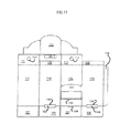
- FIG. 11 is a plan view of inner sleeve of FIG. 10A .
- FIG. 12 is a plan view of ledge with special panel cuts allowing for easier insertion of the inner sleeve into the base.
- FIG. 13 is a plan view of base of FIG. 10C with foot bridge entrance.
- FIG. 14 is a perspective view of FIG. 11 showing panel folding with visible glue flap.
- FIG. 15 is a top perspective view of double ledge with foot bridge, collapsed inside of base.
- FIG. 16 is a perspective view showing the folded double ledge partially inserted into base.
- FIG. 17 is a perspective view of assembled inner sleeve of FIG. 11
- FIG. 18 is a perspective view of partially assembled double ledge, with foot bridge of FIG. 12 .
- FIG. 19 is a perspective view of assembled base of FIG. 13 .
- FIG. 20 is a perspective view of the structures in FIGS. 10A-10C fully assembled and in open position.
- FIG. 21 is a perspective view of the bottom of inner sleeve of FIG. 11 showing the catch tabs moving to folded UP position.
- FIG. 22 is a perspective view of the inner sleeve ready to be inserted into base.
- FIG. 23 is a perspective view of the base with tabs in UP position. Tabs will be folded to DOWN position prior to inserting of inner sleeve.
- FIG. 24A is a perspective view of the inner sleeve resting on the double ledge inside the base
- FIG. 24B is a front cutaway view of the same.
- FIG. 25 is a perspective top view of the inner sleeve inside the base, with a foot inserted into the foot bridge at the bottom of the base.
- FIG. 26 is a perspective top view of the inner sleeve inside the base, with the right and left double ledge pull tabs showing.
- FIG. 27 is a perspective top view of the inner sleeve being pulled out of the base, while a foot inserted into the foot bridge at the bottom of the base.
- FIGS. 28A-28B are perspective views of the inner sleeve being placed inside the base.
- FIG. 28A shows the catch tab resting on top of the inwardly folded base catch tab.
- FIG. 28B shows the inner sleeve fully engaged inside the base, where the catch tab is not visible.
- FIG. 29 is a perspective cutaway front view of the fully engaged locking mechanism comprised of the catch tab of the inner sleeve, the catch tab of the base and the ledge.
- FIG. 30 is a cutaway side view of a further embodiment of a stop mechanism.
- FIG. 31 is a perspective cutaway front view of the inner sleeve fully collapsed inside the base.
- FIG. 32 is a perspective cutaway front view of the inner sleeve fully extended and sitting on double ledge inside the base.
- FIG. 33 is a simplified line drawing of the locking mechanism where the inner sleeve catch tab is just below the opening that will allow it to engage the inwardly facing catch tab of the base.
- FIG. 34 is a simplified line drawing of the locking mechanism where the inner sleeve catch tab is engaged with the inwardly facing catch tab of the base, and the inner sleeve is resting on the extended ledge, preventing the inner sleeve from sliding into the base.
- FIG. 35 is a perspective view of the ledge pull tabs, used to pull the ledge close to the base so that the inner sleeve may slide into the base. Pull tab(s) are useful when making retractable versions of this structure.
- FIG. 36 is a perspective view of the fully assembled structure of FIG. 11 where the pull tab is visible.
- FIG. 37 is a perspective cutaway view of the ledge pull tab being pulled.
- FIG. 38 is a perspective cutaway front view of the expanded ledge, with the pull tabs extending outside the base.
- FIG. 39 is a perspective plan view of the double ledge with foot bridge, where the foot bridge is separated from the right and left ledge.
- FIG. 40 is a perspective plan view of the double ledge with foot bridge, where the double ledge has no reinforcing spring panels.
- FIG. 41 is a perspective plan view of the double ledge with foot bridge, where the double ledge has four (two per ledge) reinforcing spring panels.
- FIG. 42 is a perspective plan view of the double ledge with foot bridge, where the double ledge has eight (four per ledge) reinforcing spring panels.
- FIG. 43 is a perspective top view of an alternate ledge, made from cut and folded panels of the base.
- FIG. 44 is a perspective top and side view of the alternate ledge of FIG. 43 , showing the cut and fold marks that create the alternate ledge.
- FIG. 45 is a perspective side and bottom view of how the alternate ledge of FIG. 43 , engages the inner sleeve.
- FIG. 46 is the same as FIG. 43 shown with FIG. 45 to help illustrate mechanics of locking mechanism.
- FIG. 47 is a perspective front view of table formed with two structures of FIGS. 28A-28B with a separate table top added.
- FIGS. 48A-48B are perspective views of a closed and open tray, respectively, that uses the same slide and lock mechanism described in this application.
- FIGS. 49A-49B are front and side cutaway views, respectively, where the inner sleeve and the base have the dimension of envelopes, where the inner sleeve may be inserted into the base envelope and be extended using the same catch tabs, with or without the folded ledge.
- FIGS. 50A-50E are perspective views of the structure of FIGS. 28A-28B with showing that the structure may be extended to “open position”, and then retracted to a “closed position”.
- FIG. 51 is a plan drawing of the Base with a modified shelf structure where panels extend upwards from the base.
- FIG. 52 is a plan drawing of a modified one piece tuck style Product Tray which does not require gluing.
- FIGS. 53A-53F are perspective drawings of plan drawings in FIGS. 51 and 52 showing a sequence of steps required to form the modified shelf structure using the folded flaps that extend from the base.
- FIGS. 54A-54B are cross-sectional views of the ledge mechanism in FIGS. 53A-53F .
- FIG. 55 shows two Insert Paddles used to assist in the placement of Product Tray into base, when using a modified embodiment of Shelf Structure shown in FIG. 12
- FIG. 56 shows how the modified Shelf Structure of FIG. 12 may be folded so that the flaps are facing inwardly inside the base so that they may extend further into the base when the Product Tray is lifted past the point where the Shelf Structure is activated.
- FIG. 57 shows how the Insert Paddle engages with the Base collapsing the Shelf Structure between the Base and the Insert Paddle so that the Product Tray may easily be inserted into the base.
- FIG. 58 shows both Insert Paddles being removed after the Product Tray has been placed into the Base.
- FIGS. 59A-59F are a perspective sequence of drawings that shows a modified Base with flap structures 701 , 702 , 703 and 704 that form a “Foot Bridge” using extended and folded flaps from the base.
- FIGS. 60A-60C show a modified Shelf Structure of FIG. 51 where the Shelf Structure is a separate internal structure that resides inside of the base, eliminating the need for having openings or slits in the Base. Also shown is an attached Foot Bridge.
- FIGS. 61A-61B are cross section views of shelf insert 800 in a “closed” position and an “open” position, respectively.
- FIG. 62 is a cross section view of a spring mechanism.
- FIG. 63 is a cross section view of the spring mechanism in the expanded or “open” position.
- FIG. 64 is a modified Shelf Structure of FIG. 60 , where an elastic band mechanism is used to automatically activate the Shelf Structure once the Product Tray is lifted past the Shelf Structure.
- FIGS. 65A-65B are cross section views of a spring mechanism used to automatically propel the internal shelf structure from a “folded” to extended position once the Product Tray is lifted past the Shelf Structure.
- FIG. 66 is a perspective view of the structure in FIGS. 65A-65B .
- FIG. 67 is a perspective drawing showing the foot pads for holding the base securely while lifting the product tray up into the deployed position.
- FIGS. 68A-68C are a sequence of drawings showing a user deploying the slide and lock display system.
- FIG. 69 is a perspective drawing that shows a Product Tray filled with heavy product being lifted with the aid of a spring mechanism.
- FIG. 70 is line drawing of a Jack-In-The-Box toy that uses a rubber band mechanism to automatically propel the inner carton to an “open” position from a “closed” position.
- FIGS. 71A-71B are perspective drawings of the Slide and Lock display structure in alternate shapes.
- inner sleeve 1 the display with a slide and lock structure of the present invention is provided and referred to generally by inner sleeve 1 , base 3 and ledge 2 .
- product tray’ and ‘inner sleeve’ are interchangeable, and similarly the terms ‘base’ and ‘outer sleeve’ are interchangeable as well.
- the simple display structure may be made from paperboard, plastic, or any combination of substrates that would form a suitable inner sleeve and base to be used for display purposes.
- the inner sleeve 23 and base 24 from other more durable materials for semi-permanent and permanent displays.
- This change in substrates may be desired for a more elegant look, or for a more durable structure.
- the materials for this alternate display structure may include but are not limited to plastic, wood metal, and other well known display and fixture materials.
- the slide and lock display would have an inner sleeve 23 with a single catch tab 9 , a single base 24 with a single catch tab 18 and ledge 2 made from paperboard or plastic.
- the ledge made from foldable paperboard such as corrugated board, is the preferred embodiment, in certain instances it may be preferred to use plastic or other suitable, foldable material that could be formed into a ledge.
- plastic or other suitable, foldable material that could be formed into a ledge.
- a solid inner sleeve 23 and base 24 may be preferred such as injection molded plastic, as often in today's competitive retail environment more and more temporary displays are combining paper board and plastic to achieve highly stylized effects.
- the display base would have a bottom 27 , either tuck flap 19 , 20 , 21 , 22 or an auto bottom (not shown) or a bottom that is glued or taped.
- An auto bottom refers to a well known packaging closure that requires no tuck flaps, but is glued and folded in manufacturing so that it sets up without the need to tuck flaps in order to assemble the structure.
- the bottom is not necessary if a separate ledge structure is added by gluing it to interior of panel 17 (not shown) so that it would have the same height as panel 12 when it supports inner sleeve from sliding back into the base.
- Many of the new specialty gluers are able to add separate structures in position and in line without a separate operation and without slowing down the manufacturing speed.
- Another way to add a ledge would be with specialty gluers that are now able to automatically glue separate tabs (ledge) to inner panels at high speeds.
- a less desirable but effective way to create the ledge is by creating a ledge by cutting and folding a tab from panel 17 . This is less desirable because it would not automatically lock. Also the cut out left by folding the ledge tab makes the display look less desirable.
- the inventor acknowledges that although these alternate options would require less parts and would cost less to produce, that most available machinery is not suited to these tricky gluing options.
- the preferred embodiment would make the slide and lock display easy to manufacture by the broadest audience, that would mean that the ledge remain a separate part.
- the inventor further acknowledges that in high volume situations, it would be more desirable to make the display from only two parts rather than three parts, as assembly of two parts would take less time than the assembly of three parts. These are some of the considerations one must decide to determine which embodiment is preferred as different applications have different requirements.
- the ledge 2 is a flat structure that is made from flexible material that is folded on fold lines 33 & 36 to create a spring action created by the memory in the material being used. It is important to note that the material being used for the ledge must be suitable for the weight of the inner sleeve. For example if the display is a greeting card, or if there is little pressure from the base as in a slide and lock display that has a horizontal application such as a shelf tray FIG. 50 then the ledge may be made from lightweight material as the inner sleeve and base. If the use is to hold heavy material, then the ledge must be made from stronger, more suited material. If the display will be in a humid or wet environment, or will be in storage for long periods of time then a more resilient material needs to be used for the ledge.
- FIGS. 5A-5C are cutaway side views that show how the slide and lock mechanism works.
- inner sleeve 23 is collapsed inside the base 24 , panels 10 , 11 and 12 of ledge 2 are compressed between exterior of inner sleeve rear panel 6 and interior of rear base panel 15 , as are catch tabs 9 and 18 , panels 10 , 11 and 12 .
- the memory created in the flexible material, from the compression puts the ledge into a spring-like state ready to expand once it has the space to do so.
- FIG. 5A inner sleeve 23
- FIG. 5A inner sleeve 23
- panels 10 , 11 and 12 of ledge 2 are compressed between exterior of inner sleeve rear panel 6 and interior of rear base panel 15 , as are catch tabs 9 and 18 , panels 10 , 11 and 12 .
- the memory created in the flexible material, from the compression puts the ledge into a spring-like state ready to expand once it has the space to do so.
- FIG. 30 FIG.
- bottom 34 of inner sleeve 23 travels past fold 11 allowing tab 18 to snap away from exterior of panel 6 and slide under tab 9 nesting between the rear of tab 9 and interior of panel 15 forming a lock and not allowing the sleeve to slide out of the base.
- ledge 2 is pushed into an extended position into open cavity 35 by the memory stored from the compression of panels 10 , 11 and 12 , forming a ledge 11 upon which bottom 34 of inner sleeve 23 can rest as shown in illustration 31 , FIG. 5C , preventing it from sliding back into base 24 .
- inner sleeve 23 and base 24 fit snug so that the contact between exterior of front panel 8 of inner sleeve 23 and interior of front panel 17 of base 24 is enough to keep the display from leaning forward or falling out. Depending on the use of the display it may be necessary to enlarge the amount of contact or overlap between these surfaces as shown in FIG. 4 at 32 . It is also important that the fit on the opposite sides is also snug but not too tight as to obstruct the movement of the inner sleeve 23 inside base 24 as it moves from closed to open position. Also if the fit is too loose the locking mechanism will not properly engage.
- FIG. 6 is a cutaway side view showing how the slide and lock mechanism may be used to create taller structures, by adding a second inner sleeve 6 B that locks into inner sleeve 6 A or 23 making the display three tiers tall. It is also important to note that an additional optional panel 38 has been added to ledge panel 12 . This panel will ensure that panel 12 remains at the intersection of bottom 20 and panel 6 A of inner sleeve 23 . Panel 38 was also added to base 24 . It is important to note that if inner sleeves 23 and 39 do not have bottoms 20 then the lower edge of panel 6 A or 6 B would slide down and rest on fold 36 .
- FIGS. 7A-7B show how this display structure has a closed position 40 ( FIG. 7A ) and open position 41 ( FIG. 7B ).
- the inner sleeve 23 may be custom die cut 43 .
- FIG. 7C is a cutaway side view of the same structure. It is the intent of the inventor to use this structure as a retail display, where an opening in base 24 allows for the presentation of product 44 (see FIG. 8 ), and inner sleeve 23 serves as a display header. It is also the intent of the inventor to use the structure as a toy.
- FIG. 9 is an example of a puppet theater where the inner sleeve 23 has a window cut out to serve as a stage.
- FIGS. 10A-10C feature one such structure consisting of three parts an inner sleeve 100 ( FIG. 10A ), a double ledge with foot-bridge 200 ( FIG. 10B ), and a base 300 ( FIG. 10C ).
- FIG. 12 introduces a double ledge with a foot-bridge 233 with foot entrance 235 .
- FIG. 14 shows the assembly of the inner sleeve 100 . Panel 117 folds over and glues to glue tab 116 .
- FIG. 17 shows the inner sleeve 100 is fully assembled.
- FIG. 18 shows the partial assembly of the double ledge with foot-bridge 233 , and
- FIG. 19 shows base 300 of FIG. 13 to complete the slide and lock display. It is the intent of the inventor to vary the style, material and construction of the double ledge panel 200 to adequately support the product weight placed in inner sleeve 100 .
- reinforcing panels 212 , 213 , 210 , 211 , 216 , 217 , 218 and 219 may be added to panels 203 and 207 , as shown in FIG. 40 , FIG. 41 and FIG. 42 , to create more weight bearing strength. Adding those panels will also create more spring tension in deployment of the double ledge.
- FIG. 16 shows a perspective view of an assembled double ledge of FIG. 18 being inserted into base 300 .
- FIG. 20 is perspective view of inner sleeve 100 of, double ledge 200 and base 300 of FIG. 10 fully assembled.
- FIG. 21 shows the inner sleeve catch tabs 103 and 104 moving from its original DOWN position to its loaded UP position. This is done by folding catch tab 104 on score 102 and catch tab 103 on score 101 , and sliding the inner sleeve inside the base.
- the inner sleeve 316 shown in FIG. 22 works the same as inner sleeve 100 except it is designed to hold stackable product.
- the catch tabs 103 and 104 are kept in the UP position because the space between the interior base panel's 302 and 304 of FIG. 13 and the exterior inner sleeve panel's 118 and 120 of FIG. 11 is deliberately too narrow to allow for the free movement of the catch tabs to naturally move to the DOWN position, while at rest or while in motion when the inner sleeve is pulled up from the base.
- FIG. 24A shows a perspective view the inner sleeve of FIG. 22 sitting inside base 316 which is shorter than the inner sleeve.
- FIG. 24B is a front cutaway view of the same structure. It is the intent of the inventor to allow the inner sleeve to be taller than the base to achieve taller structures if desired.
- FIG. 25 shows a foot 1201 being inserted into the foot-bridge 316 of base 300 as shown in FIG. 13 .
- the inner sleeve is collapsed inside of base ready for deployment.
- FIG. 26 shows pull tabs 229 and 230 . These tabs are necessary if the display needs to be retractable, if the display will deployed only once, these tabs may be removed after the inner sleeve is collapsed inside the base.
- FIG. 27 shows the relationship between the foot 1201 and the hand 1202 when the slide and lock display as it is being deployed.
- the foot is placed inside the foot-bridge 316 to prevent the base from being raised as the inner sleeve is being pulled UP by the hand 1202 from the base. Because of the tight fit between the inner sleeve and the base, if the foot 1201 was not placed inside the foot-bridge while raising the inner sleeve, the base would also be raised. It is worth noting that it is the intent of the inventor, to use this structure in applications other than floor displays.
- Finger openings 113 and 114 of FIG. 11 may be replaced by other well known handles formed either from the panels of the inner sleeve, or separately attached to the inner sleeve, by glue, tabs, rivets or other well known means of attachment.
- FIGS. 28A-28B show a perspective views of inner sleeve 100 in relationship to base 300 .
- FIG. 28A shows the inner sleeve 100 sitting on top base 300 just before the inner sleeve is pushed in side the base for shipping or storage. Note that catch tab 103 of FIG. 21 is resting on top of fold 309 , as catch tab 104 on the opposite side is sitting on fold 308 (not shown). As the inner sleeve is pushed downwards into the base, catch tabs 103 and 104 will fold upwards on folds 101 and 102 respectfully, in effect preparing the structure to perform the slide and lock mechanism.
- FIG. 28B shows the inner sleeve 100 resting inside of base 300 .
- the inner sleeve 100 is resting on top of the expanded ledge 200 with catch tabs 103 and 104 facing in the UP position where the interior of catch tab 103 is in direct contact with the exterior of panel 310 , and the interior of catch tab 104 is in direct contact with the exterior of catch panel 311 (not shown).
- FIG. 29 shows a close up cutaway front perspective view of the right side of the engaged lock mechanism and the relationship of inner sleeve 100 , double ledge 200 and base 300 as the inner sleeve 100 is pulled up from base 300 such that catch tab 104 wedges between catch panel 311 and panel 201 of double ledge 200 . It is important to note that the same locking relationship would occur if double ledge 200 did have panel 201 . In this instance catch tab 104 would wedge between the interior of catch panel 311 and the interior of base panel 304 .
- the locking tabs including catch tabs 103 and 104 and catch panels 310 and 311 may also be made of the same materials as the inner sleeve and or base, or with mixed materials. Unlike paperboard material, the permanent materials have little or no flex so the relationship and fit between the inner sleeve 100 and the base 300 would need to be such that there would be free movement between a collapsed, or closed, position and expanded, or open, position.
- the wood inner sleeve 100 complete with wood catch tab 104 would be placed inside wood base 300 between panels 207 and 203 of double ledge 200 of FIG. 32 .
- the catch tab 311 which may be made of wood, plastic, metal or other suitable material would attached in position, as shown in FIG.
- FIG. 33 and FIG. 34 are simplified line drawings of FIG. 29 showing the relationship of engagement of the lock mechanism from the left side of the structure. It is also possible that during the assembly process the inner sleeve is slid into the base from the bottom to accommodate non-flexible locking systems such as the wooden one described above.
- FIG. 35 shows the tab lock system made from panels of the double ledge, designed to hold the compressed panels of the double ledge 200 in position while loading the inner sleeve 100 . Without this restraint the tension from the compressed panels of the double ledge would force panels 203 and 207 into the center of the base 300 cavity, making it more difficult to slide the inner sleeve 100 into the base.
- Another, and for certain applications, more important function of this lock tab system is to allow the structure to easily move from the open to closed position, over and over. This feature makes the structure desirable in uses where both the open and closed positions are important as in a party candy or snack dispenser of FIG. 50 . During the party the structure is in the open or UP position.
- the lock system is comprised of lock tabs 229 and 230 that pass thru slots 220 and 221 of double ledge panels 201 and 209 and slots 306 and 307 of base 300 .
- the lock tab has flaps 222 that may be folded to easily to pass through the slots, and when unfolded will prevent the tab from slipping inside the base due to the tension caused by the folded of the panels of double ledge 200 .
- the foot-bridge may be made from material suitable to hold the weight. If necessary it may be made from solid wood with a cut in foot slot, while ledges 235 and 236 of FIG. 39 may be made from plastic corrugated. It is the intent of the inventor, to have the ability to vary the functionality of the ledge system. For example you may increase or decrease the amount of tension or the strength of the ledges by adding or removing compression panels as shown in FIG. 40 , FIG. 41 and FIG. 42 . For easier deployment of heavier inner sleeves the compression panels of double ledge 200 may be custom trimmed as shown in FIG. 10B and FIG. 12 .
- the ledges may be made shorter if it is desired to have the inner sleeve reside deeper inside the base when in the open position as shown in FIG. 4 . Also, depending on the duration of storage, and or the humidity of where the structure will be deployed, it may be necessary to have the double ledge structure may be made from different flexible materials such as plastic, plastic corrugated, rubber or other suitable materials. Further, as previously described, the ledge structure may be modified to use only a single ledge as shown in FIG. 43 . Further the ledge, or double ledge structure may be reversed in how it is folded inside the base (not shown). For example, instead of having compression panels 210 , 211 , 212 , 213 of double ledge 200 reside between ledge panel 203 and base panel 304 .
- Ledge panel 203 may be adjacent to base panel 304 , with compression panels 210 , 211 , 212 , 213 of double ledge 200 expand into the cavity of base 300 when the inner sleeve is in the UP position.
- the advantage of doing this is that the ledge structure has the ability to expand further into the base and under the inner sleeve, providing support more evenly under the inner sleeve, as it is no longer constricted by panels 203 .
- this example describes one side of a double sided ledge, the inventor acknowledges that the other side would work the same.
- the tab lock system illustrated in FIG. 36 and FIG. 38 is not the preferred method of inserting the sleeve. What is needed are separate multiple tabs per side, or a separate structure to compress the loose panels, one such system is illustrated in FIG. 57 .
- FIG. 22 are still applicable and may be used in conjunction to the folding base flap system of FIG. 45 and FIG. 46 . It is important to note that it is the intent of the inventor to vary the flaps to meet the need of the structure.
- FIG. 46 shows four flaps. This structure may also be successfully accomplished with three, two, or even one flap (not shown).
- FIG. 47 illustrates a sampling table made from two slide and lock structures and a tabletop. This would be useful as it serves both as a table and as a storage device.
- FIGS. 48A-48B show a PDQ display as used by manufacturers and retailers to showcase products.
- the advantage of this PDQ display is that it has a closed position that is far smaller than the open position. This means that in the closed position, it will ship at a smaller size, and as a result you will be able to fit a lot more displays per pallet. This means less trucks will be required to deliver the same sized order. Less trucks also means less fuel and less CO2 emissions enabling the world to enjoy a cleaner more sustainable environment.
- the PDQ display structure has a taller back and a shorter front so as to create a slope so that as the product is shopped from the front rows the product in the rear rows will slide down to the front. It is further the intent of the inventor to use this similar structure as a power wing display (not shown), where the AD MESSAGE panel of FIGS. 48A-48B oriented at the top or the bottom of the display and that hooks are placed at the rear of the display to hag the product for display.
- shipping efficiency is critical, so a collapsible structure is a desired option, and one that is well suited for the structure of this invention.
- the slide and lock structure may be made with mixed materials and in custom shapes, including round, tubular, triangular, and many other even sided or uneven sided structures (not shown).
- FIGS. 49A-49B show a further embodiment using the slide locking mechanism for a gift card, flat planar display or the like.
- FIGS. 49A-49B show a flat slide and lock structure with a top card 500 with bottom catch flap 506 that slides into envelope 501 with catch flap 507 .
- the ledge 510 is formed by cuts 502 , 508 and 509 , and fold 503 .
- Ledge 510 is activated when it is folded 504 inside envelope 501 . It is important to note, that the ledge in this case is small since the card will not require a weight-bearing ledge.
- FIGS. 50A-50E show the Slide and Lock Display as a retractable candy dispenser of FIG. 25 , FIG. 26 , FIG. 27 , and FIGS. 28A-28B as one that may be used for dispensing Halloween candy.
- the Mouth 115 is rotated to open position so as to allow easy access to candy.
- Mouth 115 is rotated to a closed position (not shown) and the Product Tray 100 is released back into Base 300 by pulling outwardly on tab 229 an and tab 230 on the opposite side (not shown) ready for storage until it's next use.
- FIG. 51 is a plan drawing of a different embodiment of Base 300 .
- This embodiment includes extended panels 601 and 602 which are modified versions of panels 250 and 251 of FIG. 12 used to form a modified version of the Inner Shelf Structure as shown in FIG. 52 .
- panels 203 and 207 are shortened, and do not reach to the bottom of Base 300 , instead the leading edges 607 and 608 are inserted into slots 604 and 603 , providing enough support so that shelf edges 227 and 228 will support Inner Product Tray 100 .
- FIG. 56 , FIG. 60C and FIG. 61B are examples of such Inserts.
- Product Tray 650 is a modified embodiment of Product Tray 100 where it is assembled with tuck flaps and does not require gluing. See FIGS. 54A-54B showing the cross-sectional view of the ledge mechanism in FIGS. 53A-53F .
- FIG. 55 is a perspective drawing of two Insert paddles used to help secure Shelf Inserts 803 and 804 inside Base 300 allowing Product Tray 100 to easily be slipped in to Base 300 .
- FIG. 56 shows modified embodiments of Shelf Inserts 251 and 250 of FIG. 12 . These Shelf Inserts expand inwardly inside Base 300 allowing Product Tray 100 to be supported not only on surfaces 227 and 228 , but also on surfaces 22 , 226 , 223 and 224 .
- FIG. 57 shows Insert Paddle 801 engaged with modified Foot Bridge 205 of FIG. 12 . Openings 805 and 806 in Foot Bridge 205 accept tabs 803 and 804 respectively, anchoring the Insert paddle as it collapses Shelf Structure 250 between Insert Paddle 801 and the interior of Base 300 . Insert Paddle 801 is locked into position when Tab 807 is pushed over the top edge of Base 300 trapping the inwardly folded flap 311 of Base 300 between the front surface of tab 807 and the rear surface of Insert Paddle 801 . This locked position is repeated on the opposite side of Base 300 with Shelf Structure 251 ad Insert Paddle 802 . Once both Insert Paddles are fully engaged, and the Shelf Structures 250 and 251 are collapsed, then Product Tray 100 may easily be lowered into Base 300 .
- FIG. 58 shows Product Tray 100 loaded with product inside of Base 300 , with Insert Paddles 801 and 802 disengaged from Foot Bridge 205 and being pulled upwards and out of Base 300 , Once Product Tray 100 is lifted past surfaces 223 , 227 and 224 of Shelf Structure 250 and surfaces 225 , 228 and 226 of Shelf Structure 251 , then Shelf Structures 250 and 251 will freely expand under Product Tray 100 .
- FIGS. 59A-59F show a perspective sequence of drawings that show a modified embodiment of Base 300 of FIG. 13 where Flaps 312 , 313 , 314 and 315 are extended and modified to form a Foot Bridge, eliminating the need to have the Foot Bridge as a separate insert.
- Locking Tab 701 is added to Flap 312
- Locking Tab 702 is added to Flap 314 .
- Base Flap 313 and Base Flap 315 are replaced by Bridge Flap 703 and Bridge Flap 704 .
- Bridge Flap 703 is formed by rolling Flap 703 inwardly so that outer surface of Panel 705 is adjacent to interior of Panel 302 .
- Bridge Flap 704 is similarly rolled.
- Bridge Flaps 704 and 703 are rolled into position, they are secured with Locking Panels 701 and 702 where tabs 706 and 708 , and Tabs 707 and 709 are inserted into slots 710 and 711 of the rolled Bridge Flaps.
- Panels 712 and corresponding panel 715 (not shown), and edges 713 and 714 form a surface that supports Product Tray 100 during shipping or storage.
- opening 316 is still used to secure the base with a store associates foot as Product Tray 100 is lifted to engage the Slide and Lock Display System.
- FIGS. 60A-60B show a modified embodiment of Product Tray 100 of FIG. 11 and modified embodiment of Base 300 of FIG. 13 , and FIG. 51 where slits 306 , 307 , 603 and 604 are eliminated from base 300 and catch Flaps 670 and 671 are added to panels 301 and 303 respectively of FIG. 13 .
- Shelf Insert 800 is comprised of panels 802 , 803 , 804 and optional panels 801 and 805 . Panels 820 and 821 are rotated inwardly so that tabs 809 and 810 are inserted into openings 807 and 808 .
- the Shelf ledge is comprised of folded edges 811 , 812 , 814 and 815 .
- Shelf Ledges are collapsed by folding Panels 820 and 821 in such a way that fold 813 is lower than folds 811 and 812 and sandwiched between Panels 822 and 823 , and Fold 816 is lower than folds 814 and 815 and sandwiched between panels 824 and 825 .
- Shelf Insert 800 it is the option of the manufacturer to place the Catch Flaps on Product Tray 100 on any two opposing panels corresponding to the Catch Flaps on Base 300 , that when engaged will prevent Product Tray 100 from exiting Base 300 . It is the intent of the inventor to allow more than two opposing Shelf Ledges in this configuration. A manufacturer may choose two, three or four Shelf Ledges and one, two, three or four Catch Flaps.
- FIG. 61A shows a cross section of Shelf Insert 800 in a “closed” position and FIG. 61B shows a cross section of Shelf Insert 800 in an “open” position where Product Tray 100 is raised past Folds 811 and 814 allowing the Shelf Insert to expand to create a-Shelf Ledge that will support Product tray 100 . It is important to note that if 826 and 827 of FIG. 60 are added, then the shelf ledge will expand further inward than if these scores are not included.
- FIG. 62 shows how the inclusion of Spring mechanism 828 may be attached or inserted between panels 821 and 804 , and between Panels 820 and 802 (not shown).
- FIG. 63 shows Spring mechanism of FIG. 62 in expanded or “open” position.
- the Spring Mechanism may be made from metal, polypropylene, polyethylene, or any other well know suitable material that can provide a flexible Spring Mechanism that will not lose its memory during storage. This addition to the structure may be desired when a display may sit in storage for an extended period of time, where the natural memory of paperboard may not be enough to expand the Shelf Structure as needed. It is Further the intent of the inventor to make the Shelf Insert from materials other than paperboard, such as plastic, corrugated plastic or any other well known materials that would maintain their memory during long periods of storage, or if they are able to offer greater support for heavier products.
- FIG. 64 is a modified embodiment of Shelf Insert 800 of FIG. 60C where the shelf structure is modified to allow for the automatic deployment of Shelf Ledges 820 and 821 by elastic means as shown in perspective drawing in FIG. 65
- FIGS. 65A-65B are cross section views of Shelf Insert 800 of FIG. 64 where elastic 853 pulls panel 821 and 820 into an extended position once Product Tray 100 is lifted past Fold 849 . It is important to note that when Panels 821 and 820 are in upright or “closed” position Tabs 810 and 809 must protrude past Openings 842 and 843 allowing Elastic 853 to move freely so that panel 821 can quickly be pulled into an extended or “open” position.
- FIG. 66 is a perspective view of FIGS. 65A-65B .
- FIG. 67 shows Base 300 of FIG. 51 where Flaps 605 and 606 replace the need for Foot Bridge 205 , and are used to secure Base 300 during the lifting of Product Tray 100 .
- This structure is desirable when a lower cost option is being considered or if there is a need for Product Tray 100 to be filled to maximum capacity, and the extra space used by the Foot Bridge 205 is not necessary.
- FIGS. 68A-68C show a sequence of steps a Store Associate would go through in setting up a Slide and lock Display System.
- Store Associate Places their foot into the Foot Bridge 205 (not shown) through slot 316 .
- Product Tray 100 is lifted up until the internal shelf Structure 250 and 251 expands from a “closed” to “open” position.
- FIG. 69 is a Slide and Lock mechanism with a Spring Mechanism designed to assist in the lifting of heavy objects. Even though most retailers have a limit of 40 lbs for displays that require lifting, the inventor contemplates the need to have a display that may be significantly heavier and will require additional assistance in lifting.
- FIG. 70 is a cut away drawing of a Jack in the Box premium that uses elastic 853 to propel Product Tray 100 into an “open” position from a “closed” position
- FIG. 71 is perspective drawings of the Slide and Lock Display System that takes on different shapes.
- the inventor contemplates that as long as the structure is able to have Catch Flaps on Product Tray 100 and Catch Flaps on Base 300 that engage once Product Tray 100 moves past the “closed” Shelf Structure and the expandable Shelf Structure resides between Product Tray 100 and Base 300 during shipping or storage, then the structure can take on many shapes.
Landscapes
- Engineering & Computer Science (AREA)
- Mechanical Engineering (AREA)
- Cartons (AREA)
- Automatic Analysis And Handling Materials Therefor (AREA)
Abstract
Description
Claims (17)
Priority Applications (1)
| Application Number | Priority Date | Filing Date | Title |
|---|---|---|---|
| US12/002,501 US7909168B2 (en) | 2006-12-16 | 2007-12-17 | Slide and lock display system |
Applications Claiming Priority (2)
| Application Number | Priority Date | Filing Date | Title |
|---|---|---|---|
| US87522506P | 2006-12-16 | 2006-12-16 | |
| US12/002,501 US7909168B2 (en) | 2006-12-16 | 2007-12-17 | Slide and lock display system |
Publications (2)
| Publication Number | Publication Date |
|---|---|
| US20080236002A1 US20080236002A1 (en) | 2008-10-02 |
| US7909168B2 true US7909168B2 (en) | 2011-03-22 |
Family
ID=39536916
Family Applications (1)
| Application Number | Title | Priority Date | Filing Date |
|---|---|---|---|
| US12/002,501 Expired - Fee Related US7909168B2 (en) | 2006-12-16 | 2007-12-17 | Slide and lock display system |
Country Status (2)
| Country | Link |
|---|---|
| US (1) | US7909168B2 (en) |
| WO (1) | WO2008076419A2 (en) |
Cited By (8)
| Publication number | Priority date | Publication date | Assignee | Title |
|---|---|---|---|---|
| US8919018B2 (en) | 2011-01-31 | 2014-12-30 | HJovic Design LLC | Method and apparatus for card image transformation and content securing |
| US8985329B2 (en) * | 2012-08-14 | 2015-03-24 | Peter Ullrich | Assemblies, systems and methods for the transportation and display of plants and flowers |
| US10507951B2 (en) | 2016-09-06 | 2019-12-17 | Otter Products, Llc | Packaging with spring loaded hanger |
| JP2020192111A (en) * | 2019-05-29 | 2020-12-03 | 大日本印刷株式会社 | Display stand |
| US10927565B2 (en) * | 2017-01-09 | 2021-02-23 | Steven M. Goldstein | Bridge adapter |
| US11161646B1 (en) | 2021-01-29 | 2021-11-02 | Buckeye Corrugated, Inc. | Box with interior lift mechanism |
| US11932464B2 (en) | 2021-05-21 | 2024-03-19 | Buckeye Corrugated, Inc. | Box with interior lift mechanism |
| US12365506B2 (en) | 2023-06-13 | 2025-07-22 | International Paper Company | Container for dispensing flexible sheet product and associated blank |
Families Citing this family (11)
| Publication number | Priority date | Publication date | Assignee | Title |
|---|---|---|---|---|
| US20100320109A1 (en) * | 2009-06-22 | 2010-12-23 | Anthony Trumbauer | Method Of Shipping and Displaying Products For Sale To Consumers And Associated Product Display |
| JP5987416B2 (en) * | 2012-03-30 | 2016-09-07 | ブラザー工業株式会社 | Packing box |
| ITFO20120011A1 (en) * | 2012-05-24 | 2013-11-25 | Harrier Srl | MOUNTING SYSTEM FOR FURNITURE |
| FR3016612B1 (en) | 2014-01-23 | 2016-07-29 | Pierre & Christian Dumas Anciens Ets Louis Dumas & Fils | TRANSFORMABLE TRANSPORT BOX IN DISPLAY |
| GB2529208B (en) * | 2014-08-13 | 2018-03-07 | Kraft Foods R&D Inc | Package assembly |
| US10767389B2 (en) * | 2017-01-09 | 2020-09-08 | Steven M. Goldstein | Bridge adapter |
| KR102080718B1 (en) * | 2018-08-30 | 2020-02-24 | 광동제약 주식회사 | Slide type display packaging box |
| PL3889058T3 (en) | 2018-11-29 | 2025-08-11 | Carlos Tomas Veraza Osorio Publicidad Spa | Tubular structural profile and construction system |
| WO2021055691A1 (en) | 2019-09-20 | 2021-03-25 | Mars, Incorporated | Product display |
| SE547464C2 (en) * | 2021-05-10 | 2025-09-30 | Stora Enso Oyj | A package formed from a kit of blanks |
| EP4406866A1 (en) * | 2023-01-26 | 2024-07-31 | Smurfit Kappa Services Limited | Shipping and point of sale display carton |
Citations (8)
| Publication number | Priority date | Publication date | Assignee | Title |
|---|---|---|---|---|
| US2253742A (en) * | 1940-05-08 | 1941-08-26 | Crown Zellerbach Corp | Dispenser for interfolded paper |
| US2627972A (en) * | 1948-05-06 | 1953-02-10 | Raymond B Roos | Sample dispensing device |
| US3918576A (en) * | 1974-06-21 | 1975-11-11 | Taub Family Trust U A Sept 1 1 | Combination shipping container and display support |
| US4191288A (en) * | 1976-08-11 | 1980-03-04 | Packaging Corporation Of America | Shipper display unit |
| US4284204A (en) | 1979-11-07 | 1981-08-18 | American Safety Razor Company | Dimpled tray package with self-locking feature |
| US4705162A (en) * | 1986-11-13 | 1987-11-10 | Kupersmit Julius B | Multiple display carton shipping package |
| US6641031B2 (en) * | 2001-08-03 | 2003-11-04 | Pharmagraphics, Inc. | Child resistant carton and method for using the same |
| US6837378B2 (en) * | 2000-04-05 | 2005-01-04 | Terry Smith Group Limited | Transportable merchandise display unit |
-
2007
- 2007-12-17 WO PCT/US2007/025761 patent/WO2008076419A2/en not_active Ceased
- 2007-12-17 US US12/002,501 patent/US7909168B2/en not_active Expired - Fee Related
Patent Citations (8)
| Publication number | Priority date | Publication date | Assignee | Title |
|---|---|---|---|---|
| US2253742A (en) * | 1940-05-08 | 1941-08-26 | Crown Zellerbach Corp | Dispenser for interfolded paper |
| US2627972A (en) * | 1948-05-06 | 1953-02-10 | Raymond B Roos | Sample dispensing device |
| US3918576A (en) * | 1974-06-21 | 1975-11-11 | Taub Family Trust U A Sept 1 1 | Combination shipping container and display support |
| US4191288A (en) * | 1976-08-11 | 1980-03-04 | Packaging Corporation Of America | Shipper display unit |
| US4284204A (en) | 1979-11-07 | 1981-08-18 | American Safety Razor Company | Dimpled tray package with self-locking feature |
| US4705162A (en) * | 1986-11-13 | 1987-11-10 | Kupersmit Julius B | Multiple display carton shipping package |
| US6837378B2 (en) * | 2000-04-05 | 2005-01-04 | Terry Smith Group Limited | Transportable merchandise display unit |
| US6641031B2 (en) * | 2001-08-03 | 2003-11-04 | Pharmagraphics, Inc. | Child resistant carton and method for using the same |
Non-Patent Citations (1)
| Title |
|---|
| PCT/US2007/025761, "PCT International Search Report and Written Opinion", Jun. 25, 2009, 8 pages. |
Cited By (9)
| Publication number | Priority date | Publication date | Assignee | Title |
|---|---|---|---|---|
| US8919018B2 (en) | 2011-01-31 | 2014-12-30 | HJovic Design LLC | Method and apparatus for card image transformation and content securing |
| US8985329B2 (en) * | 2012-08-14 | 2015-03-24 | Peter Ullrich | Assemblies, systems and methods for the transportation and display of plants and flowers |
| US10507951B2 (en) | 2016-09-06 | 2019-12-17 | Otter Products, Llc | Packaging with spring loaded hanger |
| US11186408B2 (en) | 2016-09-06 | 2021-11-30 | Otter Products, Llc | Hanger for packaging assembly |
| US10927565B2 (en) * | 2017-01-09 | 2021-02-23 | Steven M. Goldstein | Bridge adapter |
| JP2020192111A (en) * | 2019-05-29 | 2020-12-03 | 大日本印刷株式会社 | Display stand |
| US11161646B1 (en) | 2021-01-29 | 2021-11-02 | Buckeye Corrugated, Inc. | Box with interior lift mechanism |
| US11932464B2 (en) | 2021-05-21 | 2024-03-19 | Buckeye Corrugated, Inc. | Box with interior lift mechanism |
| US12365506B2 (en) | 2023-06-13 | 2025-07-22 | International Paper Company | Container for dispensing flexible sheet product and associated blank |
Also Published As
| Publication number | Publication date |
|---|---|
| US20080236002A1 (en) | 2008-10-02 |
| WO2008076419A2 (en) | 2008-06-26 |
| WO2008076419A3 (en) | 2008-08-28 |
Similar Documents
| Publication | Publication Date | Title |
|---|---|---|
| US7909168B2 (en) | Slide and lock display system | |
| US7293695B2 (en) | Interactive compartmented food package | |
| US8826833B1 (en) | Self-expanding, load-bearing mechanism for display units | |
| US8651298B2 (en) | Multi-ply laminated corrugated display rack | |
| US5322172A (en) | Collapsible display stand | |
| US8651296B2 (en) | Multi-ply laminated corrugated display rack with a back wall | |
| US4911311A (en) | Display stand with vertically stacked trays | |
| US7434340B2 (en) | Stackable folding display structure | |
| CN105407766B (en) | shipping box | |
| US20060070911A1 (en) | Base for post in post product packaging and display system | |
| US6837378B2 (en) | Transportable merchandise display unit | |
| US7905365B2 (en) | Dual container display with center panel | |
| US11470988B2 (en) | Point of sale display incorporating non-sliding, stackable and unstackable product transport boxes | |
| US20100108623A1 (en) | Folding shelf display | |
| US1947195A (en) | Display stand | |
| AU2011252744B2 (en) | Pop up brochure display/product dispensing unit | |
| US7954655B2 (en) | Display with folding shelves | |
| US20150038246A1 (en) | Repeatedly Collapsible Retail Stand Toy | |
| US5581923A (en) | Point of purchase display with attached riser card | |
| US20080237160A1 (en) | Easel display | |
| US20080203038A1 (en) | Display device for retail goods | |
| US2110934A (en) | Display carton | |
| US10364064B2 (en) | Pallet with skirt | |
| WO2008124452A1 (en) | Shelf-ready point of sale display | |
| US20230035223A1 (en) | Multi-unit stackable display with shelf-ready packaging |
Legal Events
| Date | Code | Title | Description |
|---|---|---|---|
| AS | Assignment |
Owner name: ACKER, NATHANIEL JR., CONNECTICUT Free format text: ASSIGNMENT OF ASSIGNORS INTEREST;ASSIGNOR:VIRVO, ALEXANDER;REEL/FRAME:022095/0060 Effective date: 20070315 Owner name: MARINS USA TDS, INC., CONNECTICUT Free format text: PATENT LICENSE AGREEMENT;ASSIGNOR:VLASSER LLC;REEL/FRAME:022094/0928 Effective date: 20070315 Owner name: VLASSER LLC, CONNECTICUT Free format text: ASSIGNMENT OF ASSIGNORS INTEREST;ASSIGNOR:VIRVO, ALEXANDER;REEL/FRAME:022095/0054 Effective date: 20070315 Owner name: VIRVO, ALEXANDER, CONNECTICUT Free format text: ASSIGNMENT OF ASSIGNORS INTEREST;ASSIGNOR:VLASSER LLC;REEL/FRAME:022095/0048 Effective date: 20070315 |
|
| AS | Assignment |
Owner name: VLASSER LLC, CONNECTICUT Free format text: ASSIGNMENT OF ASSIGNORS INTEREST;ASSIGNOR:ACKER, JR., NATHANIEL;REEL/FRAME:022097/0886 Effective date: 20070315 |
|
| REMI | Maintenance fee reminder mailed | ||
| LAPS | Lapse for failure to pay maintenance fees | ||
| STCH | Information on status: patent discontinuation |
Free format text: PATENT EXPIRED DUE TO NONPAYMENT OF MAINTENANCE FEES UNDER 37 CFR 1.362 |
|
| STCH | Information on status: patent discontinuation |
Free format text: PATENT EXPIRED DUE TO NONPAYMENT OF MAINTENANCE FEES UNDER 37 CFR 1.362 |
|
| FP | Lapsed due to failure to pay maintenance fee |
Effective date: 20150322 |