US7876933B2 - Methods and apparatus for estimating orientation in an image - Google Patents
Methods and apparatus for estimating orientation in an image Download PDFInfo
- Publication number
- US7876933B2 US7876933B2 US11/508,459 US50845906A US7876933B2 US 7876933 B2 US7876933 B2 US 7876933B2 US 50845906 A US50845906 A US 50845906A US 7876933 B2 US7876933 B2 US 7876933B2
- Authority
- US
- United States
- Prior art keywords
- orientation
- partial regions
- representative
- partial
- pixels
- Prior art date
- Legal status (The legal status is an assumption and is not a legal conclusion. Google has not performed a legal analysis and makes no representation as to the accuracy of the status listed.)
- Expired - Fee Related, expires
Links
Images


Classifications
-
- G—PHYSICS
- G06—COMPUTING OR CALCULATING; COUNTING
- G06V—IMAGE OR VIDEO RECOGNITION OR UNDERSTANDING
- G06V40/00—Recognition of biometric, human-related or animal-related patterns in image or video data
- G06V40/10—Human or animal bodies, e.g. vehicle occupants or pedestrians; Body parts, e.g. hands
- G06V40/12—Fingerprints or palmprints
- G06V40/1347—Preprocessing; Feature extraction
-
- G—PHYSICS
- G06—COMPUTING OR CALCULATING; COUNTING
- G06T—IMAGE DATA PROCESSING OR GENERATION, IN GENERAL
- G06T7/00—Image analysis
- G06T7/70—Determining position or orientation of objects or cameras
- G06T7/73—Determining position or orientation of objects or cameras using feature-based methods
-
- G—PHYSICS
- G06—COMPUTING OR CALCULATING; COUNTING
- G06T—IMAGE DATA PROCESSING OR GENERATION, IN GENERAL
- G06T7/00—Image analysis
- G06T7/70—Determining position or orientation of objects or cameras
- G06T7/77—Determining position or orientation of objects or cameras using statistical methods
-
- G—PHYSICS
- G06—COMPUTING OR CALCULATING; COUNTING
- G06V—IMAGE OR VIDEO RECOGNITION OR UNDERSTANDING
- G06V10/00—Arrangements for image or video recognition or understanding
- G06V10/20—Image preprocessing
- G06V10/24—Aligning, centring, orientation detection or correction of the image
- G06V10/242—Aligning, centring, orientation detection or correction of the image by image rotation, e.g. by 90 degrees
-
- G—PHYSICS
- G06—COMPUTING OR CALCULATING; COUNTING
- G06V—IMAGE OR VIDEO RECOGNITION OR UNDERSTANDING
- G06V40/00—Recognition of biometric, human-related or animal-related patterns in image or video data
- G06V40/10—Human or animal bodies, e.g. vehicle occupants or pedestrians; Body parts, e.g. hands
- G06V40/12—Fingerprints or palmprints
- G06V40/1347—Preprocessing; Feature extraction
- G06V40/1359—Extracting features related to ridge properties; Determining the fingerprint type, e.g. whorl or loop
-
- G—PHYSICS
- G06—COMPUTING OR CALCULATING; COUNTING
- G06T—IMAGE DATA PROCESSING OR GENERATION, IN GENERAL
- G06T2207/00—Indexing scheme for image analysis or image enhancement
- G06T2207/30—Subject of image; Context of image processing
- G06T2207/30004—Biomedical image processing
Definitions
- the present invention relates to methods and apparatus for estimating an orientation in an image having directivity, and more particularly, to methods and apparatus capable of accurately estimating the orientation of an image such as a fingerprint image.
- the orientation field, or orientation, of an image may be used as important information for parsing the image.
- the orientation field of the image is used intensively. For this reason, technologies for accurately analyzing the orientation field of an image have been actively researched in a variety of fields.
- fingerprint recognition is performed by using the shape of ridges and valleys of a fingerprint
- technology for accurately estimating the orientation field of a fingerprint, and the orientation of the ridges in particular, from a fingerprint image is important. Because of this importance, many research activities for technologies for measuring the orientation field of a fingerprint quickly and accurately have been conducted.
- representative ones include a technology for measuring the orientation field of a fingerprint using a neural net theory, a technology for measuring the orientation field of a fingerprint using an image filter, and a technology for measuring the orientation field using gradient information calculated from the brightness of pixels in a fingerprint image.
- the technology measuring the orientation field by using the gradient information is widely used.
- a fingerprint recognition system is a system for identifying an individual by using characteristics of a fingerprint that are different in each individual, and by using the orientation field of a fingerprint in particular.
- FIG. 1 is a block diagram of the structure of an ordinary fingerprint recognition system.
- the fingerprint recognition system includes a fingerprint image acquisition unit 110 , a fingerprint region extraction unit 130 , an orientation estimation unit 150 , a fingerprint characteristic extraction unit 170 , a fingerprint recognition unit 190 , and a fingerprint characteristic storage unit 195 .
- the fingerprint image acquisition unit 110 obtains a fingerprint image and can include a fingerprint recognition sensor to obtain only a fingerprint image, and/or can also include a camera embedded in a digital camera or a mobile phone.
- the fingerprint region extraction unit 130 extracts only a fingerprint region excluding a background in an obtained fingerprint image.
- the fingerprint orientation estimation unit 150 estimates the orientation field of a fingerprint using the structure of the ridges and valleys of the fingerprint in the extracted fingerprint region. In order to estimate the orientation field of the fingerprint, the orientation measuring technologies described above have been used.
- the fingerprint characteristic extraction unit 170 extracts the fingerprint characteristics using the orientation field of the fingerprint.
- the extracted fingerprint characteristics are stored in the fingerprint characteristic storage unit for fingerprint recognition.
- the fingerprint recognition unit 190 performs fingerprint recognition by comparing the fingerprint characteristics extracted in the fingerprint characteristic extraction unit 170 with the fingerprint characteristics stored in the fingerprint characteristic storage unit 195 .
- the fingerprint characteristics are extracted using the orientation field of the fingerprint and accordingly, accurate and fast estimation of the orientation field of the fingerprint is one of major subjects in the fingerprint recognition field.
- a clear fingerprint image when a clear fingerprint image can be obtained as in a fingerprint sensor, the orientation of the fingerprint can be easily and accurately measured.
- a clear fingerprint image cannot be obtained, for example, when a fingerprint image is obtained using an image taking apparatus, such as a digital camera and/or a mobile phone camera, the orientation of the fingerprint may not be measured accurately.
- an incorrect orientation of the fingerprint when a fingerprint image is distorted by strong external light, camera noise or a variety of factors (for example, too soft skin as those of children and women, a moist finger, and a finger with a wound), an incorrect orientation of the fingerprint may be detected.
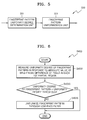
- FIG. 2 illustrates dome forms of distortion that can occur when a fingerprint image is obtained using a camera.
- the first distortion is caused by the curved circumferential shape of a finger.
- the interval between a ridge and a valley of a fingerprint is uniform in a region (region 1 ) which is level in relation to the direction of a camera lens, while both sides of the finger are sloping in relation to the direction of the camera lens and the interval between ridges and valleys gradually narrows (region 1 ′).
- the second distortion occurs because of the protruded part of the center of the fingertip.
- the shape of the ridge is clear in the central part of the finger, but the side part of the finger has a shade such that the shape of the ridge becomes unclear.
- the third distortion occurs due to wounds such as scars and/or burns on the finger skin.
- wounds such as scars and/or burns on the finger skin.
- an artificial valley is formed and thus, when the orientation of the fingerprint is measured, a ridge orientation that is totally different from that of the actual ridge orientation can be measured.
- the fourth distortion is also caused by the protruded part of the center of the fingertip. As shown in region 4 of FIG. 2 , a blurring phenomenon occurs in which due to the protruded part of the fingertip, focusing becomes partially incorrect to make the image blurred.
- the fifth distortion occurs by illumination existing when a fingerprint image is taken by a camera. That is, when a fingerprint image is taken by a camera, illumination such as camera flash light and/or sunlight can be applied to the finger. As shown in region 5 of FIG. 2 , when the illumination is applied, a phenomenon in which a predetermined region of the fingerprint image is too bright can occur.
- the orientation of the fingerprint may not be measured accurately, and in particular, when there is distortion in the fingerprint image, an incorrect orientation field of the fingerprint can be obtained.
- Some embodiments of the present invention provide methods for accurately estimating the orientation field of a fingerprint by repeatedly performing a process in which a fingerprint image is divided into partial regions and the representative orientation of the partial regions is measured, and according to the curvature of the partial regions, the partial regions are divided into smaller partial regions and the representative orientations of the smaller partial regions is measured.
- the present invention also provides an apparatus for accurately estimating the orientation of a fingerprint by repeatedly performing a process in which a fingerprint image is divided into partial regions and the representative orientation of the partial regions is measured, and according to the curvature of the partial regions, the partial regions are divided into smaller partial regions and the representative orientation of the smaller partial regions is measured.
- a method of estimating an orientation including: dividing a fingerprint image into first partial regions, measuring the gradients of pixels of the fingerprint image, and estimating representative orientations of the first partial regions; obtaining an improved fingerprint image by filtering the fingerprint image using a double orientation filter, and remeasuring the representative orientation of each of the first partial regions by remeasuring the gradients of the pixels of the improved fingerprint image; and dividing each of the first partial regions into second partial regions, and estimating the representative orientations of the second partial regions with respect to the curvature of each of the first partial regions in response to the remeasured representative orientations of the first partial regions and the remeasured gradients of the pixels.
- the methods may further include, after remeasuring the representative orientation, measuring the entire orientation of adjacent first partial regions and correcting an error of the remeasured representative orientations of the first partial regions in response to the difference of the entire orientation and the remeasured representative orientation of the first partial region.
- the methods may further include, after estimating the representative orientations of the second partial regions, determining whether or not an error exists in the estimated representative orientations of the second partial regions; and if an error exists, dividing the second partial region into sub-partial regions of smaller sizes and then, according to whether or not an error exists, estimating the representative orientation of each sub-partial region.
- the methods may further include dividing each of the sub-partial regions into sub-partial regions of smaller sizes until no error exists in the estimated representative orientations of the sub-partial regions, and then estimating the representative orientations of the divided sub-partial regions.
- an apparatus for estimating an orientation including a partial region division unit, an orientation estimation unit, and an orientation remeasuring unit.
- the partial region division unit may be configured to divide a fingerprint image into first partial regions.
- the orientation estimation unit may be configured to measure the gradient of each pixel of the fingerprint image, to estimate a representative orientation of each of the first partial regions, to obtain an improved fingerprint image by filtering the fingerprint image by using a double orientation filter, and to remeasure the representative orientations of the first partial regions by remeasuring the gradients of the pixels of the improved fingerprint image.
- the orientation remeasuring unit may be configured to divide each of the first partial regions into second partial regions, and be configured to estimate the representative orientation of each of the second partial regions with respect to the curvature of each of the first partial regions in response to the remeasured representative orientations of the first partial regions and the remeasured gradients of the pixels.
- the apparatus may further include a uniformization unit configured to adjust the uniformity of the fingerprint pattern, by processing the brightness characteristic of each first partial region, using the brightness characteristic of the fingerprint image in order to make the brightness characteristic uniform.
- a uniformization unit configured to adjust the uniformity of the fingerprint pattern, by processing the brightness characteristic of each first partial region, using the brightness characteristic of the fingerprint image in order to make the brightness characteristic uniform.
- the apparatus may further include a post-processing unit configured to measure the entire orientation of adjacent first partial regions and to correct an error of the remeasured representative orientation of each first partial region in response to the difference of the entire orientation and the remeasured representative orientation of the first partial region.
- a post-processing unit configured to measure the entire orientation of adjacent first partial regions and to correct an error of the remeasured representative orientation of each first partial region in response to the difference of the entire orientation and the remeasured representative orientation of the first partial region.
- the representative orientation error estimation unit may be further configured to determine whether or not an error exists in the estimated representative orientation of the second partial regions, and if no error exists, the representative orientation error estimation unit may output the estimated representative orientation as the fingerprint information of the fingerprint image, and if an error exists, the partial region redivision unit may divide the second partial region into sub-partial regions of smaller sizes and then, according to whether or not an error exists, the representative orientation reestimation unit may be configured to estimate the representative orientation of each divided sub-partial region according to whether or not an error exists.
- the representative orientation error measuring unit may further determine whether or not an error exists in the estimated representative orientations of the sub-partial regions, and if no error exists in the representative orientations of the sub-partial regions, the representation orientation error measuring unit may output the representative orientation of the sub-partial regions as the orientation information of the fingerprint image. If an error exists in the representative orientation of a sub-partial region, the partial region redivision unit may divide the sub-partial regions into sub-partial regions of smaller sizes, and the representative orientation reestimation unit may estimate the representative orientation of each of the divided sub-partial regions of smaller sizes.
- FIG. 1 is a block diagram of the structure of an ordinary fingerprint recognition system
- FIG. 2 illustrates distortion that can occur when a fingerprint image is obtained by using a camera
- FIG. 3 is a block diagram of an apparatus for estimating an orientation according to some embodiments of the present invention.
- FIG. 4 is a flowchart of a method of estimating an orientation according to some embodiments of the present invention.
- FIG. 5 is a block diagram of a fingerprint pattern uniformization unit of FIG. 5 according to some embodiments of the present invention.
- FIG. 6 is a flowchart of a method of adjusting a fingerprint pattern uniformly in a fingerprint pattern uniformization unit of FIG. 5 according to some embodiments of the present invention
- FIG. 7 is an operator for measuring a gradient in y and x orientations according to some embodiments of the present invention.
- FIG. 8 is a block diagram of a representative orientation estimation unit of FIG. 3 according to some embodiments of the present invention.
- FIG. 9 is a flowchart of a method of estimating the representative orientation of each of first partial regions in a representative orientation estimation unit of FIG. 8 according to some embodiments of the present invention.
- FIG. 10 illustrates examples of first partial regions of a fingerprint image in which an orientation is clear or unclear
- FIG. 11 is a block diagram of a fingerprint structure improvement unit of FIG. 3 according to some embodiments of the present invention.
- FIG. 12 is a flowchart of a method of obtaining a fingerprint image improved in a fingerprint structure improvement unit of FIG. 11 according to some embodiments of the present invention.
- FIG. 13 illustrates distinction coefficients and singularity coefficients according to some embodiments of the present invention.
- FIG. 14 illustrates a first orientation filter and a second orientation filter according to some embodiments of the present invention
- FIG. 15 illustrates examples of improved fingerprint images obtained by using a first orientation filter and a second orientation filter according to some embodiments of the present invention
- FIG. 16 illustrates a process of improving the fingerprint structure of a first partial region in which the orientation is unclear, according to some embodiments of the present invention
- FIG. 17 is a block diagram of a post-processing unit of FIG. 3 according to some embodiments of the present invention.
- FIG. 18 is a flowchart of a method of correcting an orientation error in a post-processing unit of FIG. 17 according to some embodiments of the present invention.
- FIG. 19 is a flowchart showing a detailed process of correcting an orientation error according to some embodiments of the present invention.
- FIG. 20 illustrates an example of estimating an incorrect orientation according to a curvature
- FIG. 21 is a flowchart of a method of determining a region of a larger curvature or a smaller curvature according to some embodiments of the present invention.
- FIG. 22 illustrates a process of restraining noise by estimating a representative orientation for partial regions where orientation errors by a curvature exist, according to some embodiments of the present invention.
- FIG. 23 illustrates a process of allocating an orientation to a second partial region having an orientation identity according to some embodiments of the present invention.
- the present invention may be embodied as a method, data processing system, and/or computer program product. Accordingly, the present invention may take the form of an entirely hardware embodiment, an entirely software embodiment or an embodiment combining software and hardware aspects all generally referred to herein as a “circuit” or “module.” Furthermore, the present invention may take the form of a computer program product on a computer usable storage medium having computer usable program code embodied in the medium. Any suitable computer readable medium may be utilized including hard disks, CD ROMs, optical storage devices, a transmission media such as those supporting the Internet or an intranet, or magnetic storage devices.
- These computer program instructions may also be stored in a computer readable memory that can direct a computer or other programmable data processing apparatus to function in a particular manner, such that the instructions stored in the computer readable memory produce an article of manufacture including instruction means which implement the function/act specified in the flowchart and/or block diagram block or blocks.
- the computer program instructions may also be loaded onto a computer or other programmable data processing apparatus to cause a series of operational steps to be performed on the computer or other programmable apparatus to produce a computer implemented process such that the instructions which execute on the computer or other programmable apparatus provide steps for implementing the functions/acts specified in the flowchart and/or block diagram block or blocks.
- Some embodiments of the invention provide methods and/or apparatus for accurately measuring the orientation field of a fingerprint in an unclear fingerprint image, and/or in a fingerprint image including distortion.
- a process of estimating the orientation according to some embodiments of the present invention will now be explained briefly.
- a fingerprint is divided into first partial regions (with a size of N ⁇ N pixels; N may be a size four times larger than the thickness of a ridge in order to promote correct estimation of an orientation and in some embodiments of the present invention, N is equivalent to 32 pixels) and then, a representative orientation of each of the first partial regions is measured.
- the quality of the fingerprint image may be improved by filtering the fingerprint image using a double orientation filter, and then, by remeasuring the representative orientation of the improved fingerprint image, estimation of more precise orientation is enabled.
- the second partial regions are divided into sub-partial regions having a smaller size (for example, sub-partial regions may be obtained by dividing the previous partial regions to have a size one fourth of the previous size). Then, by sequentially measuring the representative orientations of the divided smaller sub-regions, the orientation field of the fingerprint can be quickly and accurately estimated.
- FIG. 3 is a block diagram of an apparatus for estimating an orientation field according to some embodiments of the present invention
- FIG. 4 is a flowchart illustrating methods of estimating an orientation according to some embodiments of the present invention. Referring to FIGS. 3 and 4 , a process of outputting orientation information of a fingerprint image in an apparatus for estimating an orientation field according to some embodiments of the present invention will now be explained.
- the apparatus for estimating an orientation field 300 includes a partial region division unit 310 , an orientation estimation unit 350 , and an orientation reestimation unit 390 , and may further include a fingerprint pattern uniformization unit 330 and/or a post-processing unit 370 .
- the partial region division unit 310 divides a fingerprint image, which is obtained from a fingerprint image acquisition apparatus (not shown), such as a fingerprint recognition sensor, a camera, and/or a mobile phone camera, into first partial regions in operation S 401 .
- a fingerprint image acquisition apparatus not shown
- the first partial region has a size of N ⁇ N pixels, and N may be a size of 32 pixels, which may be four times larger than the thickness of a ridge.
- the apparatus for estimating an orientation 300 may further include the fingerprint pattern uniformization unit 330 .
- the uniformization unit 330 processes the brightness characteristics of respective first partial regions so that the brightness can be made to be uniform and the fingerprint pattern can be adjusted to be uniform in operation S 403 .
- the orientation estimation unit 350 measures the gradient of each of the pixels of the fingerprint image and first estimates the representative orientation of each of the first partial regions in operation S 405 , and according to the estimated representative orientations, improves the quality of the fingerprint image by filtering the image using a double orientation filter, so that an improved fingerprint image can be obtained in operation S 407 . Then, by remeasuring the gradient of each of the pixels of the improved fingerprint image, the orientation estimation unit 350 reestimates the representative orientation of each of the first partial regions in operation S 409 .
- the apparatus for estimating an orientation may further include the post-processing unit 370 .
- the post-processing unit 370 measures the entire orientation of the first partial regions adjacent to each of the first partial regions, and in response to the difference between the entire orientation and the remeasured representative orientation of each of the first partial regions, corrects the error of the remeasured representative orientation of each of the first partial regions.
- the orientation reestimation unit 390 divides each of the first partial regions into second partial regions in operation S 411 , and in response to the representative orientation of each of the first partial region reestimated in the orientation estimation unit 350 and the remeasured gradient of each pixel, estimates the representative orientation of each of the second partial regions according to the curvature of each of the first partial regions in operation S 413 .
- the orientation reestimation unit 390 determines whether or not an error exists in the representative orientation of the second partial region in operation S 415 . If it is determined that no error exists, the orientation reestimation unit 390 outputs the estimated representative orientations of the second partial regions, as the orientation information of the fingerprint image.
- the orientation reestimation unit 390 divides the second partial regions into sub-partial regions of a smaller size in operation S 417 , and estimates the representative orientation of each of the sub-partial regions in operation S 419 .
- the orientation reestimation unit 390 measures the curvature of each of the sub-partial regions, determines whether or not an error exists in the representative orientations of the sub-partial regions in operation S 415 , and outputs the representative orientation of each of the sub-partial regions as the orientation information of the fingerprint image, or repeats the process of dividing each of the sub-partial regions into sub-partial regions of a smaller size in operation S 417 and estimating the representative orientation, in operation S 419 .
- some embodiments of the present invention can accurately estimate the orientation of the fingerprint even in a fingerprint image having considerable noise.
- the second partial region has a size of M ⁇ M pixels and M may be a size of 16 pixels, which may be twice as large as the thickness of a ridge.
- the sub-partial region can be obtained by dividing a partial region before division, into four regions of an identical size. For example, when each of second partial regions is divided into four sub-partial regions, the sub-partial region has a size of 8 pixels, or about the same as the thickness of a ridge.
- FIG. 5 is a block diagram of the fingerprint pattern uniformization unit 330 of FIG. 5 and FIG. 6 is a flowchart of a method of adjusting a fingerprint pattern uniformly in the fingerprint pattern uniformization unit 330 of FIG. 5 according to some embodiments of the present invention.
- a fingerprint image is obtained from an ordinary camera or a mobile phone camera that is not a fingerprint recognition sensor
- distortion due to the effect of the strong external illumination occurs, a part having the characteristic of a fingerprint valley can exist in a fingerprint ridge region. Also, conversely, a part having the characteristic of a fingerprint ridge can exist in a fingerprint valley region.
- the uniformization unit 330 adjusts the fingerprint pattern so that the fingerprint pattern can become uniform.
- the uniformization unit 330 includes a fingerprint pattern uniformity degree determination unit 331 , and a fingerprint pattern uniformization unit 333 .
- the fingerprint pattern uniformity degree determination unit 331 measures the uniformity degree of the fingerprint pattern in response to the absolute value of the brightness difference among pixels in each of the first partial regions in operation S 4031 . If the fingerprint pattern uniformity degree is less than a predetermined uniformity degree threshold, the fingerprint pattern uniformity degree determination unit 331 determines that the region has a uniform fingerprint pattern, or else determines that the fingerprint pattern of the region is not uniform.
- the uniformity degree of a fingerprint pattern can be measured by using the following equation 1:
- Vnoise(m,n) denotes the fingerprint pattern uniformity degree of a first partial region at a location which is an m-th partial region in the x orientation and an n-th partial region in the y orientation
- x(x, y) denotes the brightness a pixel at coordinates (x, y).
- the uniformity degree threshold is determined experimentally with respect to the characteristics of an apparatus for obtaining a fingerprint image.
- the fingerprint pattern uniformization unit 333 uniformizes the fingerprint pattern of the first partial region that is determined to have a non-uniform fingerprint pattern, for example by low-pass filtering the first partial region.
- the low-pass filtering can be performed by using a Gaussian filter.
- the orientation estimation unit 350 includes a gradient measuring unit 351 , a representative orientation estimation unit 353 , and may further include a fingerprint structure improvement unit 355 .
- the gradient measuring unit 351 performs convolution operations of predetermined neighboring pixels with gradient measuring operators of the first orientation and the second orientation that are perpendicular to each other, and by doing so, measures the gradients of the first orientation and the second orientation.
- the first orientation is the x orientation and the second orientation is the y orientation.
- the image characteristic of an arbitrary pixel of the fingerprint image is more similar to the image characteristic of a second-adjacent pixel to the arbitrary pixel than the image characteristic of a pixel immediately adjacent to the arbitrary pixel.
- the absolute values of weights of the second-adjacent pixel to the central pixel in the x and y orientations are greater than the absolute values of weights of the pixel adjacent to the central pixel in the x and y orientations.
- FIG. 7 is an operator for measuring a gradient in y and x orientations according to some embodiments of the present invention.
- FIG. 7(A) shows the gradient measuring operator in the y orientation
- FIG. 7(B) shows the gradient measuring operator in the x orientation.
- the y orientation operator has a size of 3 ⁇ 5 pixels
- the x orientation operator has a size of 5 ⁇ 3 pixels.
- the absolute value of the weight of each of pixels adjacent to the central pixel in the x and y orientations is 1, and the absolute value of the weight of each of pixels second-adjacent to the central pixel in the x and y orientations is 2.
- the weight of the central pixel and pixels adjacent to the central pixel in a direction transverse to the direction of the operator are 0 each.
- xGradient(x, y) and yGradient(x, y) denote the gradients of a pixel at coordinates (x, y) in the x orientation and in the y orientation, respectively
- p(x, y) denotes the grayscale value of
- FIG. 8 is a block diagram of the representative orientation estimation unit 353 of FIG. 3
- FIG. 9 is a flowchart of a method of estimating the representative orientation of each of first partial regions in the representative orientation estimation unit 353 of FIG. 8 .
- the representative orientation estimation unit 353 measures the orientation of each pixel by using the gradient of the pixel in operation S 4053 .
- the measured orientation of each pixel is quantized in operation S 4055 , the histogram for each first partial region is obtained, and an orientation in which the histogram has a maximum value, is estimated as the representative orientation of the first partial region in operation S 4057 .
- the representative orientation estimation unit 353 includes an orientation information measuring unit 3531 , a quantization unit 3533 , and a representative orientation determination unit 3535 .
- the orientation information measuring unit 3531 measures the orientation of each pixel in response to the ratio of the gradient of the first orientation (that is, x orientation) and the gradient of the second orientation (that is, y orientation) in operation S 4053 . That is, the orientation of each pixel is measured by using the following equation 3:
- O ⁇ ( x , y ) 180 ⁇ ⁇ tan - 1 ⁇ ( yGradient ⁇ ( x , y ) xGradient ⁇ ( x , y ) ) ( 3 )
- O(x,y) denotes the orientation of a pixel at coordinates (x, y)
- xGradient(x, y) and yGradient(x, y) denote the gradients of a pixel at coordinates (x, y) in the x orientation and in the y orientation, respectively.
- the quantization unit 3533 quantizes the orientation of each pixel in a predetermined angle unit in operation S 4055 .
- the orientation of each pixel is quantized in 180 degree/Z units and Z is 180. Accordingly, the orientation of each pixel is quantized in 1 degree units and in 180 steps.
- the representative orientation determination unit 3535 obtains a histogram for the quantized value, and determines an orientation corresponding to a quantized value in which the histogram has a maximum value, as a representative orientation in operation S 4057 .
- a histogram is expressed as the following equation 4:
- Hmn denotes the histogram of a first partial region at a location which is an m-th partial region in the x orientation and an n-th partial region in the y orientation
- the histogram of each first partial region indicates the distribution of the numbers of identical quantization values.
- the location at which the histogram has a maximum value is a location where the number of identical quantization values has a maximum value. Therefore in each first partial region, the number of pixels having an orientation corresponding to the quantization value in which the histogram has a maximum value is the largest. Accordingly, the representative orientation determination unit 3535 determines the orientation corresponding to the quantization value of a location where the histogram has a maximum value, as the representative orientation.
- FIG. 10 illustrates examples of first partial regions of a fingerprint image in which an orientation is clear or unclear. Assuming that the gradient in the x orientation is based on the x axis, and the gradient in the y orientation is based on the y axis, the distribution of points in FIG. 10 indicates the distribution of the gradient of each pixel in the first partial region and each arrow is a representative orientation of the first partial region obtained by using the distribution of the gradient.
- the fingerprint structure when there is no distortion in the fingerprint image, the fingerprint structure is clear and the representative orientation of the first partial region can be estimated clearly. But, if there is a distortion in the fingerprint image, the fingerprint structure is not clear and the representative orientation of the first partial region cannot be estimated clearly. Accordingly, when there is a serious distortion, it is needed to improve the structure of the ridge and valley of the fingerprint for a better fingerprint image and then, to estimate again the fingerprint orientation.
- the orientation estimation unit 350 may further include a fingerprint structure improvement unit 355 .
- the fingerprint structure improvement unit 355 determines whether or not the fingerprint image of each first partial region is clear, and by using a double orientation filter, improves the fingerprint image of each first partial region so that an improved fingerprint image can be obtained.
- a method of obtaining an improved fingerprint image in the fingerprint structure improvement unit 355 will now be explained with reference to FIGS. 11 and 12 .
- FIG. 11 is a block diagram of the fingerprint structure improvement unit 355 of FIG. 3 and FIG. 12 is a flowchart of a method of obtaining a fingerprint image improved in the fingerprint structure improvement unit 355 .
- the fingerprint structure improvement unit 355 includes a fingerprint clearness determination unit 3551 , a first orientation filter 3553 , a second orientation filter 3555 , and a fingerprint image improvement unit 3557 .
- the fingerprint structure clearness determination unit 3551 measures the distinction coefficient and clearness coefficient in each first partial region in operation S 4031 , and by doing so, determines whether or not the fingerprint structure in the first partial region is clear.
- the distinction coefficient is a coefficient indicating a probability that a ridge and a valley exist, that is, the degree that the ridge and valley of a fingerprint image are clearly distinguished, and can be measured by using the following equation 5:
- a single orientation coefficient is a coefficient indicating the degree that the structure of the ridge and valley of a fingerprint image forms a single orientation, and can be measured by using the following equations 6, 7-1, and 7-2:
- FIG. 13 illustrates distinction coefficients and singularity coefficients with FIGS. 13 (A)- 1 and (A)- 2 explaining the distinction coefficients and FIGS. 13 (B)- 1 and (B)- 2 explaining the single orientation coefficients.
- the distribution of the gradient shows concentration on the center.
- FIG. 13 (A)- 2 when the ridge and valley are clearly distinguished, the gradient has a predetermined orientation and has a wider distribution.
- the distinction coefficient is a coefficient indicating this characteristic. When the ridge and valley are clearly distinguished and the gradient has a predetermined orientation with a wider distribution, the distinction has a larger value.
- the gradient should have a distribution with a predetermined single orientation. As shown in FIG. 13 (B)- 2 , when the fingerprint ridge has a distribution without a predetermined single orientation, the gradient has a wide distribution in all orientations.
- the single orientation coefficient is a coefficient indicating this characteristic. When the fingerprint ridge has a predetermined single orientation and the gradient has a narrower distribution, the single orientation coefficient has a larger value.
- the fingerprint structure clearness determination unit 3551 determines whether or not the distinction coefficient measured in each first partial region is greater than a predetermined distinction threshold, and the single orientation coefficient is greater than a predetermined single orientation threshold in operation S 4073 . If the distinction coefficient and the single orientation coefficient are greater, it is determined that the fingerprint structure of the first partial region is clear, or else it is determined that the fingerprint structure of the first partial region is not clear.
- the fingerprint structure is improved according to the determination result.
- the fingerprint image is improved by using a double orientation filter according to the estimated orientation.
- the double orientation filter includes a first orientation filter 3553 and a second orientation filter 3555 .
- the double orientation filter will now be explained with reference to FIG. 14 .
- FIG. 14 illustrates a first orientation filter and a second orientation filter according to some embodiments of the present invention, with FIG. 14 (A) showing the first orientation filter and FIG. 14 (B) showing the second orientation filter.
- both the first orientation filter 3553 and the second orientation filter 3555 are one-dimensional filter for predetermined 4 orientations.
- the predetermined 4 orientations are 0, 45, 90, and 135 degrees.
- the first orientation filter 3553 has a characteristic emphasizing the boundary of a ridge and a valley of an orientation corresponding to the orientation of a central pixel.
- the second orientation filter 3555 has a characteristic removing noise existing in a ridge and a valley of an orientation corresponding to the orientation of the central pixel.
- a pixel in which the boundary of a ridge and a valley is desired to be emphasized is taken as a central pixel, and the weight in each of pixels immediately adjacent to the central pixel are the same as the weight of the central pixel.
- the weight in each second-adjacent pixel to the central pixel has a sign opposite to the weight of the central pixel and has a less absolute value than that of the weight of the central pixel.
- the weight in each third-adjacent pixel to the central pixel has a sign opposite to the weight of the central pixel and has the same absolute value as that of the weight of the central pixel.
- the weight of the central pixel and the weight of each of pixels immediately adjacent to the central pixel are 2, the weight in each of the second-adjacent pixels to the central pixel is ⁇ 1, and the weight of each of the third-adjacent pixels to the central pixel is ⁇ 2.
- a pixel in which noise in the ridge and valley is desired to be removed is taken as a central pixel, and the weight in the central pixel has a maximum.
- the weight in each pixel immediately adjacent to the central pixel and the weight in each second-adjacent pixel to the central pixel are less than the weight in the central pixel.
- the weight in each third-adjacent pixel to the central pixel is less than the weight in each of the second-adjacent pixels to the central.
- the weight in the central pixel is 3, the weight in each of pixels immediately adjacent to the central pixel and the weight in each second-adjacent pixel to the central pixel are 2 each, and the weight in each third-adjacent pixel to the central pixel is 1.
- FIG. 15 illustrates examples of improved fingerprint images obtained by using the first orientation filter 3553 and the second orientation filter 3555 .
- FIG. 15 (A) shows a fingerprint image in which the boundary of a ridge and a valley is strengthened by using the first orientation filter 3553 , and it can be seen that after filtering is performed with the first orientation filter 3553 , the boundary of the ridge and valley becomes clearer.
- FIG. 15 (B) shows a fingerprint image in which noise in the ridge is removed by using the second orientation filter 3555 , and it can be seen that after filtering is performed with the second orientation filter 3555 , noise in the ridge is removed such that the uniformity of the ridge structure is improved.
- the fingerprint image improvement unit 3557 improves a fingerprint image by applying a double orientation filter, and a double orientation filter with an orientation appropriate to a fingerprint image should be applied.
- the fingerprint image improvement unit 3557 improves the fingerprint image of each first partial region by a different method according to whether or not the fingerprint structure of each first partial region is clear.
- the fingerprint image improvement unit 3557 performs filtering of each of the first partial region by using the first orientation filter and the second orientation filter of the representative orientation of each of the first partial region in operation S 4075 .
- the fingerprint image improvement unit 3557 performs filtering of each first partial region by using the first orientation filter and the second orientation filter of each of four orientations, and measures clearness of each of the four orientations of the filtered fingerprint image of each first partial region in operation S 4079 .
- the clearness of each of the four orientations of each first partial region is measured in response to the power of each orientation after the filtering using the first orientation filter is performed and the single orientation coefficient of each orientation after the filtering using the second orientation filter is performed.
- the clearness in some embodiments of the present invention is measured by using the following equations 8 through 10:
- C reactivity ⁇ ⁇ C RS i + ⁇ ⁇ C RNR i ( 8 )
- the fingerprint image improvement unit 3557 selects an image corresponding to an orientation in which the clearness becomes a maximum, among image passing through the first and second orientation filters, and by doing so, can improve the fingerprint image of the first partial regions that are determined to be unclear in operation S 4079 .
- FIG. 16 illustrates a process of improving the fingerprint structure of a first partial region in which the orientation is unclear.
- FIG. 16 (A) shows the fingerprint image of the first partial region that is determined to be unclear and the gradient distribution.
- FIG. 16 (B) through (E) show fingerprint images filtered by applying double orientation filters of 0, 45, 90, and 135 degrees, respectively, to the fingerprint image of FIG. 16 (A).
- the fingerprint image improvement unit 3557 selects the fingerprint image of FIG. 16 (C) and replaces the fingerprint image (A) so that the fingerprint image can be improved.
- the gradient measuring unit 351 remeasures the gradient of each pixel of the improved fingerprint image
- the representative orientation estimation unit 353 reestimates the representative orientation of each first partial region by using the remeasured gradient.
- the method of remeasuring the gradient and reestimating the representative orientation is performed in the same manner as the first measuring of the representative orientation, and therefore the detailed explanation will be omitted.
- a method of correcting an error of the orientation of each first partial region in response to the orientations of adjacent first partial regions is used.
- the orientation estimation apparatus 300 may further include the post-processing unit 370 to correct the error of an orientation.
- the post-processing unit 370 measures the entire orientation of the adjacent first partial regions, and in response to the difference of the entire orientation and the remeasured representative orientation of each first partial region, corrects the error of the representative orientation of each first partial region. The operation of correcting the error of the orientation will now be explained with reference to FIGS. 17 through 19 .
- FIG. 17 is a block diagram of the post-processing unit 370 of FIG. 3 .
- FIG. 18 is a flowchart of a method of correcting an orientation error in the post-processing unit 370 of FIG. 17
- FIG. 19 is a flowchart showing a detailed process of correcting an orientation error according to some embodiments of the present invention.
- the post-processing unit 370 includes an adjacent region orientation evaluation unit 371 , an orientation difference measuring unit 373 , an orientation error determination unit 375 , and an orientation error correction unit 379 .
- the adjacent region orientation evaluation unit 371 measures the difference of the remeasured representative orientations of the neighboring first partial regions adjacent to the current partial region and predetermined angles, and in response to the mean value of the differences, evaluates the entire orientation of the adjacent first partial regions in operation S 1801 .
- the predetermined angle is 90 degrees
- the adjacent region orientation evaluation unit 371 measures the mean value of the differences (
- the orientation difference measuring unit 373 measures the orientation difference of the entire orientation and the representative orientation of each first partial region.
- the orientation difference measuring unit 373 measures the orientation difference by a different method according to whether the entire orientation is vertical or horizontal in operation S 1803 .
- the difference is measured by using the following equation 11, and, if the entire orientation is horizontal, the difference is measured by using the following equation 12:
- ⁇ ′ 90 denotes the orientation difference when the entire orientation is vertical
- ⁇ ′ 0 denotes the orientation difference when the entire orientation is horizontal
- ⁇ denotes the orientation of a current region
- ⁇ i denotes the representative orientation of an adjacent first partial region to the left, to the right, below and above the current region, respectively.
- the orientation error determination unit 375 compares the orientation difference measured in relation to each first partial region, with a predetermined orientation difference threshold in order to determine whether or not an error occurs in the representation orientation of each first partial region in operation S 1805 . In some embodiments of the present invention, the orientation error determination unit 375 determines that an error occurs in the representative orientation, if the orientation difference is equal to or less than the orientation difference threshold.
- the orientation error correction unit 377 corrects the orientation error for the first partial regions in which-errors occur in operation S 1807 .
- the orientation error correction unit 377 determines that the current region and the immediately adjacent first partial regions in the horizontal direction are in the same orientation, and corrects the orientation error of the current region in response to the mean value of the representative orientations of the first partial regions immediately adjacent to the current region in the horizontal direction, by using the following equation 14 in operation S 1905 :
- ⁇ [ y ] ⁇ [ x ] 1 2 ⁇ ⁇ ⁇ [ y ] ⁇ [ x - 1 ] + ⁇ [ y ] ⁇ [ x + 1 ] ⁇ ( 14 )
- ⁇ [x][y] denotes the representative orientation of the first partial region in which the orientation error is corrected.
- (15) ⁇ [y][x+1]
- the orientation error correction unit 377 determines that the orientations of the current region and the immediately adjacent first partial regions in the horizontal direction are horizontal, and in response to the mean value of the representative orientations of the adjacent first partial regions in the horizontal direction, corrects the orientation error of the current region in operation S 1905 .
- the orientation error correction unit 377 determines that the orientations of the current region and the immediately adjacent first partial regions in the horizontal direction are vertical, and by using asymmetry of the adjacent first partial regions in the horizontal direction, corrects the error.
- each first partial region is estimated, if there is a region of a large curvature, such as a core point and a delta point, in the fingerprint image of the first partial region, two or more orientations may exist in the first partial region.
- FIG. 20 illustrates an example of estimating an incorrect orientation according to a curvature.
- FIG. 20 (B) shows an orientation that actually exists in the first partial region
- FIG. 20 (A) shows a representative orientation incorrectly estimated and different from the actual orientation in the first partial region in which the curvature is high. Accordingly, in a region of a large curvature, it is needed to divide each first partial region into smaller second partial regions and to estimate the representative orientation.
- the orientation reestimation unit 390 divides each first partial region into second partial regions in operation S 411 , and according to the curvature of each first partial region, estimates the representative orientation of each second partial region in response to the representative orientation of each first region reestimated in the orientation estimation unit 350 and the remeasured gradient of each pixel in operation S 413 .
- the orientation reestimation unit 390 includes a partial region redivision unit 393 , a representative orientation error measuring unit 391 , and a representative orientation reestimation unit 395 .
- the partial region redivision unit 393 divides each first partial region into second partial regions. The method of determining a region of a high curvature or a low curvature in the representative orientation error measuring unit 391 will now be explained with reference to FIG. 21 .
- the representative orientation error measuring unit 391 measures the curvature by using the vertical orientation difference with the representative orientations of the adjacent first partial regions in the vertical direction and the horizontal orientation difference with the representative orientations of the adjacent first partial regions in the horizontal direction in operation S 2101 .
- (18) ⁇ h ⁇
- (19) ⁇ Cv ⁇ ⁇ v ⁇ ⁇ h ⁇ (20) where ⁇ v ⁇ and ⁇ h ⁇ denote the vertical orientation difference and the horizontal orientation difference, respectively, ⁇ Cv ⁇ denotes the curvature, and ⁇ and ⁇ denote proportionality constants determined according to the characteristics of a fingerprint acquisition apparatus.
- the representative orientation error measuring unit 391 compares the curvature with a predetermined curvature threshold in operation S 2103 . If the curvature is greater than the curvature threshold, the representative error measuring unit 391 determines that the curvature is small in operation S 2105 , and if the curvature is less than the curvature threshold, determines that the curvature is large in operation S 2107 .
- the representative orientation error measuring unit 391 may determine that an error exists in the representative orientation. The case where it is determined that an error exists in the representative orientation will be explained later.
- the representative orientation reestimation unit 395 estimates the representative orientation of each second partial region according to whether the curvature of the region is large or small.
- the representative orientation reestimation unit 395 selects only the gradients that satisfy predetermined pass conditions among gradients of pixels of the first partial region, in response to the representative orientation of the first partial region to which each second partial region belongs, and estimates the representative orientation of each second partial region in response to the selected gradient.
- the second partial region is smaller than the first partial region, the second partial region is more sensitive to noise. Accordingly, in some embodiments of the present invention, in order to estimate the representative orientation of each second partial region, noise is restricted by using the representative orientation of each first partial region and then, the representative orientation of the second partial region is estimated.
- FIG. 22 illustrates a process of restraining noise by estimating a representative orientation for partial regions where orientation errors exist as a result of curvature, according to some embodiments of the present invention.
- a predetermined pass region ( FIG. 22 (A)) corresponding to the representative orientation of the first partial region is set, and by using only the gradient of pixels inside the predetermined pass region, the representative orientation of the second partial region is estimated such that noise ( FIG. 22 (B) and (C)) can be restricted.
- the representative orientation reestimation unit 395 selects only the gradients satisfying the pass region conditions among the gradients of pixels of the first partial region, and newly defines a gradient to estimate the representative orientation of each second partial region.
- the pass region conditions are given as the following equations 21 and 22: Gy ⁇ tan( ⁇ +90) Gx+ ⁇ pb (21) Cy >tan( ⁇ +90) Gx ⁇ pb (22) where (Gx, Gy) denotes the gradient of the first partial region, and ⁇ pb denotes a constant determined according to the characteristic of a fingerprint acquisition apparatus.
- the representative orientation reestimation unit 395 allocates the representative orientation of the first partial region, to each second partial region belonging to the first partial region as the representative orientation.
- the method of allocating the representative orientation by the representative orientation reestimation unit 39 is based on the linear characteristic of a ridge.
- FIG. 23 illustrates a process of allocating an orientation to a second partial region having an orientation identity according to some embodiments of the present invention.
- the method of allocating a representative orientation by the representative orientation reestimation unit 395 will now be explained in detail with reference to FIG. 23 .
- each first partial region is divided into four second partial regions of a same size, and each second partial region is defined as shown in FIG. 23 . That is, when the first partial region is divided into four second partial regions, regions MM 0 , MM 1 , MM 2 , and MM 3 are defined on the xy-plane, as a region between (0, 0) and (N/2, N/2), a region between (N/2, 0) and (N, N/2), a region between (0, N/2) and (N/2, N), and a region between (N/2, N/2) and (N, N), respectively.
- the representative orientation reestimation unit 395 measures the vertical orientation difference with the first partial regions adjacent in the vertical direction to the first partial region to which each second partial region belongs, and the horizontal orientation difference with the first partial regions adjacent in the horizontal direction to the first partial region.
- (23-1) ⁇ h 1 [y][x]
- (23-2) ⁇ h 2 [y][x]
- (23-3) ⁇ h 3 [y][x]
- (23-4) ⁇ v 0 [y][x]
- (24-1) ⁇ v 1 [y][x]
- (25-1) ⁇ MM 2 [j][i] 1 ⁇ 4
- (25-2) ⁇ MM 3 [j][i] 1 ⁇ 4
- the orientation estimation apparatus 300 estimates the orientation by dividing the first partial region into second partial regions having smaller sizes, such that the fingerprint orientation can be accurately estimated.
- the representative orientation error measuring unit 391 can determine that an error exists in the estimated representative orientation.
- the representative error measuring unit 391 can further determine whether or not an error exists in the representative orientation of each second partial region. If there is no error, the representative orientation error estimation unit 391 outputs the estimated representative orientation as the orientation information of the fingerprint image.
- the partial region redivision unit 393 divides each of the second partial regions into sub-partial regions of smaller sizes, and the representative orientation reestimation unit 395 estimates the representative orientation of each of the divided sub-partial regions according to whether or not an error exists.
- the representative orientation error measuring unit 391 can further determine whether or not an error exists in the estimated representative orientation of each sub-partial region.
- the representative orientation error measuring unit 391 outputs the representative orientation of each sub-partial region as the orientation information of the fingerprint image.
- the partial region redivision unit 393 divides each of the sub-partial regions into sub-partial regions of smaller sizes, and the representative orientation reestimation unit 395 estimates the representative orientation of each of the divided sub-partial regions of smaller sizes.
- the orientation reestimation unit 390 determines whether or not an error exists in the representative orientation of each partial region of a predetermined size, and until no error exists in the representative orientation, repeatedly performs the process of dividing each partial region into sub-partial regions of smaller sizes and estimating the representative orientation. By doing so, the orientation information of a fingerprint can be accurately extracted even from a fingerprint image with a serious distortion.
- methods of estimating an orientation may have an advantage that the orientation of the fingerprint can be accurately measured even in the regions in which the curvature of a ridge changes greatly, such as a core point and a delta point.
- methods of estimating an orientation may accurately measure the orientation of a fingerprint from a fingerprint image distorted by a variety of external factors.
- methods of estimating an orientation may accurately measure the orientation of a fingerprint even in case where a clear fingerprint image cannot be obtained, such as when a fingerprint image is obtained by using a digital camera or a mobile phone camera.
Landscapes
- Engineering & Computer Science (AREA)
- Physics & Mathematics (AREA)
- Theoretical Computer Science (AREA)
- General Physics & Mathematics (AREA)
- Computer Vision & Pattern Recognition (AREA)
- Multimedia (AREA)
- Human Computer Interaction (AREA)
- Life Sciences & Earth Sciences (AREA)
- Bioinformatics & Cheminformatics (AREA)
- Bioinformatics & Computational Biology (AREA)
- Evolutionary Biology (AREA)
- Probability & Statistics with Applications (AREA)
- Image Analysis (AREA)
- Collating Specific Patterns (AREA)
- Image Processing (AREA)
Abstract
Description
where Vnoise(m,n) denotes the fingerprint pattern uniformity degree of a first partial region at a location which is an m-th partial region in the x orientation and an n-th partial region in the y orientation, and x(x, y) denotes the brightness a pixel at coordinates (x, y). In some embodiments of the present invention, the uniformity degree threshold is determined experimentally with respect to the characteristics of an apparatus for obtaining a fingerprint image.
where xGradient(x, y) and yGradient(x, y) denote the gradients of a pixel at coordinates (x, y) in the x orientation and in the y orientation, respectively, p(x, y) denotes the grayscale value of a pixel at coordinates (x, y), Ox(x, y) and Oy(x, y) denote gradient measuring operators in the x orientation and in the y orientation, respectively, with a pixel at coordinates (x, y) as a central pixel.
where O(x,y) denotes the orientation of a pixel at coordinates (x, y), and xGradient(x, y) and yGradient(x, y) denote the gradients of a pixel at coordinates (x, y) in the x orientation and in the y orientation, respectively.
where Hmn denotes the histogram of a first partial region at a location which is an m-th partial region in the x orientation and an n-th partial region in the y orientation, and K(1)=1, and 1 is a value obtained by quantizing the orientation of each pixel. As shown in the
where Ch1 denotes a distinction coefficient.
where, Ch2 denotes is a single orientation coefficient, and θ denotes the estimated representative orientation of each first partial region.
where Creactivity i denotes the clearness degree in i-th orientation in each first partial region, CRSi denotes the power in i-th orientation in each first partial region after the filtering using the first orientation filter is performed, CRNRi denotes the single orientation coefficient in i-th orientation of each first partial region after the filtering using the second orientation filter is performed, and α and β denote predetermined constants corresponding to conditions under which the fingerprint image is taken. In some embodiments of the present invention, α and β are determined by the characteristic of a fingerprint acquisition apparatus, and external conditions when the fingerprint is obtained. In some embodiments of the present invention, the clearness degree becomes higher as the fingerprint structure of a fingerprint image becomes clearer.
where Δθ′90 denotes the orientation difference when the entire orientation is vertical, Δθ′0 denotes the orientation difference when the entire orientation is horizontal, Δθ denotes the orientation of a current region, wi and vi are weights that have {1, 1, 2, 2} and {2, 2, 1, 1,}, respectively, when i=1, 2, 3, and 4, and when i=1, 2, 3, and 4, θi denotes the representative orientation of an adjacent first partial region to the left, to the right, below and above the current region, respectively.
ΔOri θ[x][y]=(θ[x][y−1]−90)×(θ[x][y+1]−90) (13)
where ΔOriθ[x][y] denotes a vertical orientation identity coefficient in the current region, θ[x][y−1] denotes the representative orientation of the first partial region adjacent to and below the current region, θ[x][y+1] denotes the representative orientation of the first partial region adjacent to and above the current region.
where θ[x][y] denotes the representative orientation of the first partial region in which the orientation error is corrected.
Δθ[y][x−1]=|θ[y][x−1]−90| (15)
Δθ[y][x+1]=|θ[y][x+1]−90| (16)
where Δθ[y][x−1] denotes the first horizontal orientation identity coefficient, and Δθ[y][x+1] denotes the second horizontal orientation identity coefficient.
θ[y][x]=mod180 {θ[y][x−1]+θ[y][x+1]} (17)
where mod180{n} denotes an operator calculating the remainder of dividing n by 180.
Δv θ=||θ[y−1][x]−θ[y+1][x]|−90| (18)
Δh θ=||θ[y][x−1]−θ[y][x+1]|−90| (19)
ΔCv θ =αΔv θ βΔh θ (20)
where Δvθ and Δhθ denote the vertical orientation difference and the horizontal orientation difference, respectively, ΔCvθ denotes the curvature, and α and β denote proportionality constants determined according to the characteristics of a fingerprint acquisition apparatus.
Gy<tan(θ+90)Gx+β pb (21)
Cy>tan(θ+90)Gx−β pb (22)
where (Gx, Gy) denotes the gradient of the first partial region, and βpb denotes a constant determined according to the characteristic of a fingerprint acquisition apparatus.
Δθh
Δθh
Δθh
Δθh
Δθv
Δθv
Δθv
Δθv
where Δθhi and Δθvi denote the horizontal orientation difference and the vertical orientation difference in region MMi, respectively, θNN[y][x] denotes the representative orientation of the first partial region to which region MMi belongs, and θNN[y+1][x], θNN[y−1][x], θNN[y][x−1] and θNN[y][x+1] denote the representative orientations of the adjacent first partial region to above, below, to the left and to the right of the first partial region, respectively, to which region MMi belongs to.
θMM
θMM
θMM
θMM
Claims (46)
Δv θ=∥θ[y−1][x]−θ[y+1][x]|−90|
Δh θ=∥θ[y][x−1]−θ[y][x+1]|−90|
ΔCv θ =αΔv θ +βΔh θ
Applications Claiming Priority (3)
| Application Number | Priority Date | Filing Date | Title |
|---|---|---|---|
| KR10-2005-0077531 | 2005-08-23 | ||
| KR1020050077531A KR100825773B1 (en) | 2005-08-23 | 2005-08-23 | Direction estimation method and apparatus |
| KR10/2005-0077531 | 2005-08-23 |
Publications (2)
| Publication Number | Publication Date |
|---|---|
| US20070047785A1 US20070047785A1 (en) | 2007-03-01 |
| US7876933B2 true US7876933B2 (en) | 2011-01-25 |
Family
ID=37804134
Family Applications (1)
| Application Number | Title | Priority Date | Filing Date |
|---|---|---|---|
| US11/508,459 Expired - Fee Related US7876933B2 (en) | 2005-08-23 | 2006-08-23 | Methods and apparatus for estimating orientation in an image |
Country Status (4)
| Country | Link |
|---|---|
| US (1) | US7876933B2 (en) |
| KR (1) | KR100825773B1 (en) |
| DE (1) | DE102006041645B4 (en) |
| GB (1) | GB2431762B8 (en) |
Cited By (5)
| Publication number | Priority date | Publication date | Assignee | Title |
|---|---|---|---|---|
| US20090285459A1 (en) * | 2008-05-15 | 2009-11-19 | Gaurav Aggarwal | Fingerprint representation using gradient histograms |
| CN102609705A (en) * | 2012-01-20 | 2012-07-25 | 西安电子科技大学 | Low-quality fingerprint image direction field extraction method based on diffusion equation |
| EP3109823A1 (en) | 2015-06-22 | 2016-12-28 | Sick IVP AB | Method and arrangements for estimating one or more dominating orientations in a digital image |
| US10262185B2 (en) | 2016-05-30 | 2019-04-16 | Au Optronics Corporation | Image processing method and image processing system |
| US11138408B2 (en) * | 2019-01-03 | 2021-10-05 | Samsung Electronics Co., Ltd. | Method and apparatus for verifying fingerprint |
Families Citing this family (63)
| Publication number | Priority date | Publication date | Assignee | Title |
|---|---|---|---|---|
| US20070244844A1 (en) * | 2006-03-23 | 2007-10-18 | Intelliscience Corporation | Methods and systems for data analysis and feature recognition |
| US20080031548A1 (en) * | 2006-03-23 | 2008-02-07 | Intelliscience Corporation | Systems and methods for data transformation |
| US8625885B2 (en) | 2006-03-23 | 2014-01-07 | Intelliscience Corporation | Methods and systems for data analysis and feature recognition |
| WO2008022222A2 (en) * | 2006-08-15 | 2008-02-21 | Intelliscience Corporation | Systems and methods for data transformation |
| KR100834995B1 (en) * | 2006-09-28 | 2008-06-04 | 한국외국어대학교 연구산학협력단 | Fingerprint Matching Device and Method |
| RU2329537C1 (en) * | 2006-11-08 | 2008-07-20 | Владимир Николаевич Бичигов | Method of fingerprint image filtration |
| JP4821663B2 (en) * | 2007-03-12 | 2011-11-24 | 日本電気株式会社 | Character noise elimination device, character noise elimination method, character noise elimination program |
| US8175992B2 (en) | 2008-03-17 | 2012-05-08 | Intelliscience Corporation | Methods and systems for compound feature creation, processing, and identification in conjunction with a data analysis and feature recognition system wherein hit weights are summed |
| JP5061988B2 (en) * | 2008-03-25 | 2012-10-31 | 日本電気株式会社 | Ridge direction extraction device, ridge direction extraction program, and ridge direction extraction method |
| JP4599457B1 (en) * | 2009-09-18 | 2010-12-15 | 株式会社東芝 | Image processing apparatus, display apparatus, and image processing method |
| KR100997616B1 (en) * | 2010-05-18 | 2010-12-01 | 주식회사 슈프리마 | Rotating fingerprint acquisition device and method using matching and synthesis |
| HK1206842A1 (en) * | 2012-02-24 | 2016-01-15 | 尤比奎特广播公司 | Feature detection filter using orientation fields |
| US9436864B2 (en) * | 2012-08-23 | 2016-09-06 | Apple Inc. | Electronic device performing finger biometric pre-matching and related methods |
| CN103077377B (en) | 2012-12-31 | 2015-07-29 | 清华大学 | Based on the fingerprint correction method of field of direction distribution |
| CN103020610A (en) * | 2012-12-31 | 2013-04-03 | 清华大学 | Automatic distorted fingerprint detecting method |
| KR102123092B1 (en) | 2013-11-21 | 2020-06-15 | 삼성전자주식회사 | Method for identifying fingerprint and electronic device thereof |
| CN103646238B (en) * | 2013-12-19 | 2016-09-21 | 清华大学 | The method of estimation of Fingerprint diretion and device |
| KR101529033B1 (en) * | 2014-02-14 | 2015-06-18 | 크루셜텍 (주) | Electronic device comprising minimum sensing area and fingerprint information processing method thereof |
| KR102206054B1 (en) | 2014-05-09 | 2021-01-21 | 삼성전자주식회사 | Method for processing fingerprint and electronic device thereof |
| CN103996025B (en) * | 2014-05-15 | 2017-04-19 | 清华大学 | Fingerprint twisting degree estimation method and system |
| CN105205802B (en) * | 2015-02-13 | 2017-04-12 | 比亚迪股份有限公司 | Method and device for calculating ridge distance |
| CN104732217B (en) * | 2015-03-27 | 2018-04-06 | 电子科技大学 | A kind of adaptive template size Fingerprint diretion computational methods |
| CN108427932B (en) * | 2015-10-19 | 2021-07-02 | Oppo广东移动通信有限公司 | Fingerprint image recognition method and device |
| US10445547B2 (en) | 2016-05-04 | 2019-10-15 | Invensense, Inc. | Device mountable packaging of ultrasonic transducers |
| US10315222B2 (en) | 2016-05-04 | 2019-06-11 | Invensense, Inc. | Two-dimensional array of CMOS control elements |
| US10656255B2 (en) | 2016-05-04 | 2020-05-19 | Invensense, Inc. | Piezoelectric micromachined ultrasonic transducer (PMUT) |
| US10670716B2 (en) | 2016-05-04 | 2020-06-02 | Invensense, Inc. | Operating a two-dimensional array of ultrasonic transducers |
| US10452887B2 (en) | 2016-05-10 | 2019-10-22 | Invensense, Inc. | Operating a fingerprint sensor comprised of ultrasonic transducers |
| US10562070B2 (en) | 2016-05-10 | 2020-02-18 | Invensense, Inc. | Receive operation of an ultrasonic sensor |
| US10706835B2 (en) | 2016-05-10 | 2020-07-07 | Invensense, Inc. | Transmit beamforming of a two-dimensional array of ultrasonic transducers |
| US11673165B2 (en) | 2016-05-10 | 2023-06-13 | Invensense, Inc. | Ultrasonic transducer operable in a surface acoustic wave (SAW) mode |
| US10539539B2 (en) | 2016-05-10 | 2020-01-21 | Invensense, Inc. | Operation of an ultrasonic sensor |
| US10632500B2 (en) | 2016-05-10 | 2020-04-28 | Invensense, Inc. | Ultrasonic transducer with a non-uniform membrane |
| US10441975B2 (en) | 2016-05-10 | 2019-10-15 | Invensense, Inc. | Supplemental sensor modes and systems for ultrasonic transducers |
| CN107704839B (en) * | 2016-05-27 | 2021-04-23 | Oppo广东移动通信有限公司 | A fingerprint unlocking method, device, user terminal and media product |
| KR20180086087A (en) | 2017-01-20 | 2018-07-30 | 삼성전자주식회사 | Method for processing fingerprint information |
| CN107066991A (en) * | 2017-05-10 | 2017-08-18 | 上海为然环保科技有限公司 | A kind of fingerprint verifying apparatus |
| US10474862B2 (en) | 2017-06-01 | 2019-11-12 | Invensense, Inc. | Image generation in an electronic device using ultrasonic transducers |
| US10643052B2 (en) | 2017-06-28 | 2020-05-05 | Invensense, Inc. | Image generation in an electronic device using ultrasonic transducers |
| US10997388B2 (en) | 2017-12-01 | 2021-05-04 | Invensense, Inc. | Darkfield contamination detection |
| US10984209B2 (en) | 2017-12-01 | 2021-04-20 | Invensense, Inc. | Darkfield modeling |
| WO2019109010A1 (en) | 2017-12-01 | 2019-06-06 | Invensense, Inc. | Darkfield tracking |
| US11151355B2 (en) * | 2018-01-24 | 2021-10-19 | Invensense, Inc. | Generation of an estimated fingerprint |
| US10664715B2 (en) * | 2018-03-16 | 2020-05-26 | University Of Wolverhampton | Computer-implemented print analysis |
| US10755067B2 (en) | 2018-03-22 | 2020-08-25 | Invensense, Inc. | Operating a fingerprint sensor comprised of ultrasonic transducers |
| US10102415B1 (en) * | 2018-03-29 | 2018-10-16 | Secugen Corporation | Method and apparatus for simultaneous multiple fingerprint enrollment |
| US10936843B2 (en) | 2018-12-28 | 2021-03-02 | Invensense, Inc. | Segmented image acquisition |
| US11188735B2 (en) | 2019-06-24 | 2021-11-30 | Invensense, Inc. | Fake finger detection using ridge features |
| US11216681B2 (en) | 2019-06-25 | 2022-01-04 | Invensense, Inc. | Fake finger detection based on transient features |
| US11216632B2 (en) | 2019-07-17 | 2022-01-04 | Invensense, Inc. | Ultrasonic fingerprint sensor with a contact layer of non-uniform thickness |
| US11176345B2 (en) | 2019-07-17 | 2021-11-16 | Invensense, Inc. | Ultrasonic fingerprint sensor with a contact layer of non-uniform thickness |
| US11232549B2 (en) | 2019-08-23 | 2022-01-25 | Invensense, Inc. | Adapting a quality threshold for a fingerprint image |
| US11392789B2 (en) | 2019-10-21 | 2022-07-19 | Invensense, Inc. | Fingerprint authentication using a synthetic enrollment image |
| EP3822982A1 (en) * | 2019-11-17 | 2021-05-19 | PreciPoint GmbH | Method of determining and displaying an area of interest of a digital microscopic tissue image, input / output system for navigating a patient-specific image record, and work place comprising such input / output system |
| CN115551650A (en) | 2020-03-09 | 2022-12-30 | 应美盛公司 | Ultrasonic fingerprint sensor with contact layer of non-uniform thickness |
| US11243300B2 (en) | 2020-03-10 | 2022-02-08 | Invensense, Inc. | Operating a fingerprint sensor comprised of ultrasonic transducers and a presence sensor |
| US11328165B2 (en) | 2020-04-24 | 2022-05-10 | Invensense, Inc. | Pressure-based activation of fingerprint spoof detection |
| JP7140304B2 (en) * | 2020-06-29 | 2022-09-21 | 日本電気株式会社 | Information processing system, information processing method and program |
| US11995909B2 (en) | 2020-07-17 | 2024-05-28 | Tdk Corporation | Multipath reflection correction |
| US12174295B2 (en) | 2020-08-07 | 2024-12-24 | Tdk Corporation | Acoustic multipath correction |
| CN112699863B (en) * | 2021-03-25 | 2022-05-17 | 深圳阜时科技有限公司 | Fingerprint enhancement method, computer readable storage medium and electronic device |
| US12416807B2 (en) | 2021-08-20 | 2025-09-16 | Tdk Corporation | Retinal projection display system |
| US12260050B2 (en) | 2021-08-25 | 2025-03-25 | Tdk Corporation | Differential receive at an ultrasonic transducer |
Citations (14)
| Publication number | Priority date | Publication date | Assignee | Title |
|---|---|---|---|---|
| US5261008A (en) | 1990-08-07 | 1993-11-09 | Yozan, Inc. | Fingerprint verification method |
| US5267324A (en) * | 1990-07-05 | 1993-11-30 | Ezel, Inc. | Image comparison method |
| US5717788A (en) | 1995-04-18 | 1998-02-10 | Iterated Systems, Inc. | Method and system for analyzing data |
| US6263091B1 (en) * | 1997-08-22 | 2001-07-17 | International Business Machines Corporation | System and method for identifying foreground and background portions of digitized images |
| US6289112B1 (en) | 1997-08-22 | 2001-09-11 | International Business Machines Corporation | System and method for determining block direction in fingerprint images |
| US6314197B1 (en) | 1997-08-22 | 2001-11-06 | International Business Machines Corporation | Determining an alignment estimation between two (fingerprint) images |
| DE10027657A1 (en) | 2000-06-03 | 2001-12-13 | Bosch Gmbh Robert | Reference points detection method for fingerprint image analysis, involves detecting regression line of spectral power density of filtered image regions to judge orientation of papillary lines |
| US20030039382A1 (en) * | 2001-05-25 | 2003-02-27 | Biometric Informatics Technolgy, Inc. | Fingerprint recognition system |
| EP1288856A1 (en) | 2001-08-01 | 2003-03-05 | Siemens Aktiengesellschaft | Reconstruction of erroneus image values in a image composed of picture elements |
| KR20030019788A (en) | 2001-08-31 | 2003-03-07 | (주)니트 젠 | Method of extracting fingerprint features using ridge direction model |
| DE10239342A1 (en) | 2002-08-28 | 2004-03-11 | Philips Intellectual Property & Standards Gmbh | Procedure for evaluating the quality of skin imprint images |
| DE10260642A1 (en) | 2002-12-23 | 2004-07-15 | Siemens Ag | Finger prints reference formulation method e.g. for criminalistics, involves accepting minutiae as well as orientation field of finger print in reference |
| US6766040B1 (en) * | 2000-10-02 | 2004-07-20 | Biometric Solutions, Llc | System and method for capturing, enrolling and verifying a fingerprint |
| JP2005010842A (en) | 2003-06-16 | 2005-01-13 | Mitsubishi Electric Corp | Striped pattern extraction system and striped pattern extraction method |
Family Cites Families (5)
| Publication number | Priority date | Publication date | Assignee | Title |
|---|---|---|---|---|
| JPS63308679A (en) * | 1987-06-11 | 1988-12-16 | Secom Co Ltd | Ridge direction detection device for ridge pattern |
| KR910020595A (en) * | 1990-05-30 | 1991-12-20 | 이헌조 | Directional Detection System of Fingerprint Image |
| JPH0495175A (en) * | 1990-08-07 | 1992-03-27 | Takayama:Kk | Fingerprint collating method |
| JP2725599B2 (en) * | 1994-06-21 | 1998-03-11 | 日本電気株式会社 | Ridge direction extraction device |
| KR20040057210A (en) * | 2002-12-26 | 2004-07-02 | (주)모멘트그룹 | Apparatus and Method for Recognizing Hologram Fingerprint |
-
2005
- 2005-08-23 KR KR1020050077531A patent/KR100825773B1/en not_active Expired - Fee Related
-
2006
- 2006-08-23 DE DE102006041645A patent/DE102006041645B4/en active Active
- 2006-08-23 GB GB0616736A patent/GB2431762B8/en active Active
- 2006-08-23 US US11/508,459 patent/US7876933B2/en not_active Expired - Fee Related
Patent Citations (14)
| Publication number | Priority date | Publication date | Assignee | Title |
|---|---|---|---|---|
| US5267324A (en) * | 1990-07-05 | 1993-11-30 | Ezel, Inc. | Image comparison method |
| US5261008A (en) | 1990-08-07 | 1993-11-09 | Yozan, Inc. | Fingerprint verification method |
| US5717788A (en) | 1995-04-18 | 1998-02-10 | Iterated Systems, Inc. | Method and system for analyzing data |
| US6263091B1 (en) * | 1997-08-22 | 2001-07-17 | International Business Machines Corporation | System and method for identifying foreground and background portions of digitized images |
| US6289112B1 (en) | 1997-08-22 | 2001-09-11 | International Business Machines Corporation | System and method for determining block direction in fingerprint images |
| US6314197B1 (en) | 1997-08-22 | 2001-11-06 | International Business Machines Corporation | Determining an alignment estimation between two (fingerprint) images |
| DE10027657A1 (en) | 2000-06-03 | 2001-12-13 | Bosch Gmbh Robert | Reference points detection method for fingerprint image analysis, involves detecting regression line of spectral power density of filtered image regions to judge orientation of papillary lines |
| US6766040B1 (en) * | 2000-10-02 | 2004-07-20 | Biometric Solutions, Llc | System and method for capturing, enrolling and verifying a fingerprint |
| US20030039382A1 (en) * | 2001-05-25 | 2003-02-27 | Biometric Informatics Technolgy, Inc. | Fingerprint recognition system |
| EP1288856A1 (en) | 2001-08-01 | 2003-03-05 | Siemens Aktiengesellschaft | Reconstruction of erroneus image values in a image composed of picture elements |
| KR20030019788A (en) | 2001-08-31 | 2003-03-07 | (주)니트 젠 | Method of extracting fingerprint features using ridge direction model |
| DE10239342A1 (en) | 2002-08-28 | 2004-03-11 | Philips Intellectual Property & Standards Gmbh | Procedure for evaluating the quality of skin imprint images |
| DE10260642A1 (en) | 2002-12-23 | 2004-07-15 | Siemens Ag | Finger prints reference formulation method e.g. for criminalistics, involves accepting minutiae as well as orientation field of finger print in reference |
| JP2005010842A (en) | 2003-06-16 | 2005-01-13 | Mitsubishi Electric Corp | Striped pattern extraction system and striped pattern extraction method |
Non-Patent Citations (1)
| Title |
|---|
| Search Report for European Application No. 0616736.5, mailed Dec. 27, 2006. |
Cited By (7)
| Publication number | Priority date | Publication date | Assignee | Title |
|---|---|---|---|---|
| US20090285459A1 (en) * | 2008-05-15 | 2009-11-19 | Gaurav Aggarwal | Fingerprint representation using gradient histograms |
| US8625861B2 (en) * | 2008-05-15 | 2014-01-07 | International Business Machines Corporation | Fingerprint representation using gradient histograms |
| CN102609705A (en) * | 2012-01-20 | 2012-07-25 | 西安电子科技大学 | Low-quality fingerprint image direction field extraction method based on diffusion equation |
| EP3109823A1 (en) | 2015-06-22 | 2016-12-28 | Sick IVP AB | Method and arrangements for estimating one or more dominating orientations in a digital image |
| US10114995B2 (en) | 2015-06-22 | 2018-10-30 | Sick Ivp Ab | Method and arrangements for estimating one or more dominating orientations in a digital image |
| US10262185B2 (en) | 2016-05-30 | 2019-04-16 | Au Optronics Corporation | Image processing method and image processing system |
| US11138408B2 (en) * | 2019-01-03 | 2021-10-05 | Samsung Electronics Co., Ltd. | Method and apparatus for verifying fingerprint |
Also Published As
| Publication number | Publication date |
|---|---|
| GB0616736D0 (en) | 2006-10-04 |
| KR20070023217A (en) | 2007-02-28 |
| DE102006041645A1 (en) | 2007-05-03 |
| US20070047785A1 (en) | 2007-03-01 |
| GB2431762B8 (en) | 2008-07-10 |
| GB2431762A (en) | 2007-05-02 |
| DE102006041645B4 (en) | 2010-11-11 |
| GB2431762A8 (en) | 2008-07-09 |
| GB2431762B (en) | 2008-07-02 |
| KR100825773B1 (en) | 2008-04-28 |
Similar Documents
| Publication | Publication Date | Title |
|---|---|---|
| US7876933B2 (en) | Methods and apparatus for estimating orientation in an image | |
| US11861813B2 (en) | Image distortion correction method and apparatus | |
| CN110264426B (en) | Image distortion correction method and device | |
| EP2678824B1 (en) | Determining model parameters based on transforming a model of an object | |
| US20230419453A1 (en) | Image noise reduction | |
| US8576289B2 (en) | Blur correction device and blur correction method | |
| US7689034B2 (en) | Learning method for detectors, face detection method, face detection apparatus, and face detection program | |
| US9053540B2 (en) | Stereo matching by census transform and support weight cost aggregation | |
| US9760997B2 (en) | Image noise reduction using lucas kanade inverse algorithm | |
| US20060291741A1 (en) | Image processing apparatus, image processing method, program, and recording medium therefor | |
| US20110142363A1 (en) | Image correction apparatus and image correction method | |
| CN111696049A (en) | Deep learning-based underwater distorted image reconstruction method | |
| CN1863272A (en) | Ultra-resolution ratio reconstructing method for video-image | |
| CN118154442B (en) | Edge feature enhancement method and device, storage medium and electronic equipment | |
| CN117557820A (en) | A method and system for damage detection of quantum dot optical films based on machine vision | |
| US20110129167A1 (en) | Image correction apparatus and image correction method | |
| CN113409375B (en) | Image processing method, image processing apparatus, and non-volatile storage medium | |
| EP4172935B1 (en) | Method and electronic device for determining boundary of region of interest | |
| US20250111530A1 (en) | Fisheye image processing method, electronic device, and computer-readable storage medium | |
| CN112308812A (en) | Method, terminal and storage medium for detecting picture definition | |
| CN110827313B (en) | Fast optical flow tracking method and related equipment | |
| US7539352B2 (en) | Image filter, image filtering method and computer program | |
| CN119722729B (en) | Digital coding point and dynamic pose measurement method based on digital coding point | |
| CN119879776A (en) | Phase deviation application method and system based on orthogonal imaging model | |
| CN121837026A (en) | Model construction and image processing method and device and computer equipment |
Legal Events
| Date | Code | Title | Description |
|---|---|---|---|
| AS | Assignment |
Owner name: SAMSUNG ELECTRONICS CO., LTD., KOREA, REPUBLIC OF Free format text: ASSIGNMENT OF ASSIGNORS INTEREST;ASSIGNORS:JANG, WON-CHURL;LEE, DONG-JAE;PARK, DEOK-SOO;REEL/FRAME:018211/0334 Effective date: 20060818 |
|
| STCF | Information on status: patent grant |
Free format text: PATENTED CASE |
|
| FPAY | Fee payment |
Year of fee payment: 4 |
|
| MAFP | Maintenance fee payment |
Free format text: PAYMENT OF MAINTENANCE FEE, 8TH YEAR, LARGE ENTITY (ORIGINAL EVENT CODE: M1552) Year of fee payment: 8 |
|
| FEPP | Fee payment procedure |
Free format text: MAINTENANCE FEE REMINDER MAILED (ORIGINAL EVENT CODE: REM.); ENTITY STATUS OF PATENT OWNER: LARGE ENTITY |
|
| LAPS | Lapse for failure to pay maintenance fees |
Free format text: PATENT EXPIRED FOR FAILURE TO PAY MAINTENANCE FEES (ORIGINAL EVENT CODE: EXP.); ENTITY STATUS OF PATENT OWNER: LARGE ENTITY |
|
| STCH | Information on status: patent discontinuation |
Free format text: PATENT EXPIRED DUE TO NONPAYMENT OF MAINTENANCE FEES UNDER 37 CFR 1.362 |
|
| FP | Lapsed due to failure to pay maintenance fee |
Effective date: 20230125 |