US7863978B1 - RF amplifier system for neutralizing internal capacitance in a cavity - Google Patents
RF amplifier system for neutralizing internal capacitance in a cavity Download PDFInfo
- Publication number
- US7863978B1 US7863978B1 US12/557,565 US55756509A US7863978B1 US 7863978 B1 US7863978 B1 US 7863978B1 US 55756509 A US55756509 A US 55756509A US 7863978 B1 US7863978 B1 US 7863978B1
- Authority
- US
- United States
- Prior art keywords
- transformer
- cavity
- grid
- set forth
- cathode
- Prior art date
- Legal status (The legal status is an assumption and is not a legal conclusion. Google has not performed a legal analysis and makes no representation as to the accuracy of the status listed.)
- Expired - Fee Related
Links
Images


Classifications
-
- H—ELECTRICITY
- H03—ELECTRONIC CIRCUITRY
- H03F—AMPLIFIERS
- H03F1/00—Details of amplifiers with only discharge tubes, only semiconductor devices or only unspecified devices as amplifying elements
- H03F1/34—Negative-feedback-circuit arrangements with or without positive feedback
- H03F1/36—Negative-feedback-circuit arrangements with or without positive feedback in discharge-tube amplifiers
-
- H—ELECTRICITY
- H03—ELECTRONIC CIRCUITRY
- H03F—AMPLIFIERS
- H03F3/00—Amplifiers with only discharge tubes or only semiconductor devices as amplifying elements
- H03F3/189—High-frequency amplifiers, e.g. radio frequency amplifiers
-
- H—ELECTRICITY
- H03—ELECTRONIC CIRCUITRY
- H03F—AMPLIFIERS
- H03F2200/00—Indexing scheme relating to amplifiers
- H03F2200/423—Amplifier output adaptation especially for transmission line coupling purposes, e.g. impedance adaptation
-
- H—ELECTRICITY
- H03—ELECTRONIC CIRCUITRY
- H03F—AMPLIFIERS
- H03F2200/00—Indexing scheme relating to amplifiers
- H03F2200/451—Indexing scheme relating to amplifiers the amplifier being a radio frequency amplifier
-
- H—ELECTRICITY
- H03—ELECTRONIC CIRCUITRY
- H03F—AMPLIFIERS
- H03F2200/00—Indexing scheme relating to amplifiers
- H03F2200/541—Transformer coupled at the output of an amplifier
Definitions
- This invention is directed to RF broadcast transmission and communication systems in general and is particularly related to improving the stability and efficiency of radio frequency power amplifiers.
- the cavity is an enclosed cavity that contains the transmitting tube, such as a tetrode.
- a transmitting tube such as a tetrode.
- Such a tube employs at least a cathode, an anode and a grid.
- the tube exhibits an internal grid to anode capacitance which provides an error factor during the operation. Consequently, it is important during the set-up procedure to neutralize this internal capacitance and this is frequently referred to as neutralizing the cavity.
- the present invention minimizes dirt collection and arcing problems that have been associated with neutralization methods, thus far employing variable capacitors. Additionally, the invention places the anode sampling capacitors at DC ground potential and this will protect the control grid in the event of plate arcing. Also, the invention minimizes the need to add a high current, capacitor divider at the ground end of the grid tuning inductors which may drift in value during warm-up operation.
- the inventive approach allows the neutralization technique to be adjusted from outside the cavity without disturbing the cavity resonance. Tube changes can be made quickly and manufacturing test time can be greatly reduced employing the invention.
- an RF amplifier system employs an enclosed cavity containing an amplifier device that includes at least a cathode, an anode and a grid wherein the amplifying device exhibits an internal grid to anode characteristic capacitance.
- the invention employs an apparatus for neutralizing the internal capacitance.
- This includes a feedback circuit that includes an external capacitor of fixed value together with a phase inverting transformer having a transformer primary winding connected in series from the capacitor to the cathode.
- This transformer employs a secondary winding connected between the cathode and the grid for purposes of supplying a phase inverted negative feedback voltage to the grid for purposes of neutralizing the internal capacitance of the cavity.
- the external capacitor is located in the cavity and the transformer coupling between the primary winding and the secondary winding is adjustable for adjusting the value of the feedback voltage supplied to the grid.
- the transformer coupling includes one of the transformer windings.
- the transformer coupling includes the primary winding of the transformer and this winding is adjustable.
- the adjustable primary winding includes a tapped primary winding.
- the transformer coupling employs a strip line transformer.
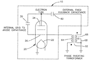
- FIG. 1 is a schematic circuit diagram illustrating relevant prior art
- FIG. 2 is a schematic circuit diagram illustrating a first embodiment of the present invention.
- FIG. 3 is a circuit diagram illustrating a second embodiment of the present invention.
- the present invention is directed toward improvements to an RF amplifier system such as those employed in broadcasting RF signals.
- a system employs an amplifying device that is located in an enclosed resonant cavity.
- a cavity is illustrated in the prior art of FIG. 1 and includes a cavity 10 .
- a resonant cavity or cavity resonator may be defined as any region bounded by conducting walls within which resonant electromagnetic fields may be excited.
- the cavity 10 is bounded by conducting walls so as to provide a container within which the cavity contains an amplifying device 20 .
- This amplifying device includes a cathode 22 , an anode 24 and a grid 26 .
- An internal grid-to-anode capacitance is illustrated in FIG.
- a voltage builds up across this internal capacitance and this serves as an error factor.
- a negative feedback is supplied by means of the secondary winding of a transformer 50 .
- This transformer has its primary winding connected in series with a variable capacitor 52 between ground and the anode 24 .
- the secondary winding supplies the grid 26 with an inverted opposing voltage to neutralize the voltage built up at the internal grid-to-anode capacitance. This is achieved by employing the circuit as illustrated, including the variable capacitance 52 connected in series with the primary winding 54 of transformer 50 .
- the secondary winding 56 of the transformers supplies the inverting opposing voltage to the grid 46 .
- the prior art requires that the external capacitor 52 be adjusted. To achieve this, entrance must be obtained into the cavity 10 .
- the cavity is typically a metal container having entrance by means of a door that is fastened to the periphery of a hole located in a sidewall of the metal container. This typically may require bolting and unbolting a plurality of screws or bolts and the like, all of which takes considerable time.
- This doorway will be opened and then closed and a measurement will be made as to the level of voltage in the cavity at the capacitance 30 . This process will be repeated until satisfactory results are obtained in neutralizing the cavity.
- the invention herein employs neutralization of the cavity by making adjustments outside of the cavity without disturbing the cavity resonance and, hence, tube changes can be made quickly and manufacturing test time can be greatly reduced.
- FIGS. 2 and 3 These two embodiments employ circuitry located externally of the cavity 10 and, consequently, adjustments can be made in the magnitude of the negative feedback voltage applied to the grid of the amplifying device without disturbing the cavity resonance.
- FIG. 2 presents circuitry similar to that as illustrated in FIG. 1 and, consequently, like components are identified with like character references. Only the differences in the circuitry of FIG. 2 will be described in detail below.
- this embodiment of the invention incorporates a small fixed capacitance capacitor 60 which couples a small amount of energy directly off the tube anode 24 .
- This voltage sample is then scaled and inverted by a transformer 62 .
- This transformer has a secondary winding 64 that supplies a 180° phase shift voltage to the grid 26 .
- This voltage is adjusted with an adjustable primary winding 66 having an adjustable center tap 68 . The adjustment is made so as to be equal and opposite to the voltage coupled through the anode to the grid capacitor 30 .
- the transformer primary is adjustable and is located external to the cavity 10 . Consequently, adjustment of the feedback voltage can be made easily outside the cavity.
- the amount of negative feedback can be adjusted. This allows the feedback capacitor 60 to be a fixed value and entrance into the cavity 10 to adjust the feedback voltage is not employed.
- FIG. 3 illustrates a second embodiment of the invention.
- the various circuit components that are similar to those in FIG. 1 are identified with like character references. Only the differences in the two circuits are described herein in detail.
- This embodiment is similar to that of the embodiment of FIG. 2 , but it is intended for use at higher frequencies, such as VHF frequencies, and employs a strip line transformer 70 .
- This transformer includes a primary strip 72 and a secondary strip 74 .
- the primary strip 72 employs a sliding short 76 to adjust the value of the feedback voltage supplied to the grid 26 .
- This feedback voltage is of opposite polarity to that of the voltage across the internal capacitance 30 .
- the adjustable transformer winding is illustrated as being on the primary side of the transformer. This could also be obtained by providing the adjustable transformer winding on the secondary of the transformer.
Landscapes
- Engineering & Computer Science (AREA)
- Power Engineering (AREA)
- Amplifiers (AREA)
Abstract
Description
Claims (10)
Priority Applications (1)
| Application Number | Priority Date | Filing Date | Title |
|---|---|---|---|
| US12/557,565 US7863978B1 (en) | 2009-09-11 | 2009-09-11 | RF amplifier system for neutralizing internal capacitance in a cavity |
Applications Claiming Priority (1)
| Application Number | Priority Date | Filing Date | Title |
|---|---|---|---|
| US12/557,565 US7863978B1 (en) | 2009-09-11 | 2009-09-11 | RF amplifier system for neutralizing internal capacitance in a cavity |
Publications (1)
| Publication Number | Publication Date |
|---|---|
| US7863978B1 true US7863978B1 (en) | 2011-01-04 |
Family
ID=43384973
Family Applications (1)
| Application Number | Title | Priority Date | Filing Date |
|---|---|---|---|
| US12/557,565 Expired - Fee Related US7863978B1 (en) | 2009-09-11 | 2009-09-11 | RF amplifier system for neutralizing internal capacitance in a cavity |
Country Status (1)
| Country | Link |
|---|---|
| US (1) | US7863978B1 (en) |
Cited By (1)
| Publication number | Priority date | Publication date | Assignee | Title |
|---|---|---|---|---|
| US11082020B2 (en) * | 2019-06-17 | 2021-08-03 | Hyundai Motor Company | Apparatus for attenuating noise in vehicle and control method thereof |
Citations (5)
| Publication number | Priority date | Publication date | Assignee | Title |
|---|---|---|---|---|
| US2235198A (en) * | 1936-04-24 | 1941-03-18 | Telefunken Gmbh | Anode neutralizing circuit for short waves |
| US2257570A (en) * | 1937-09-11 | 1941-09-30 | Rca Corp | Neutralized system |
| US3382450A (en) * | 1965-11-12 | 1968-05-07 | Avco Corp | Neutralizing circuits for push-pull and cathanode stages |
| US3617915A (en) * | 1969-06-29 | 1971-11-02 | Hitachi Ltd | Tuning circuit having a neutralizing circuit |
| US3835406A (en) * | 1972-10-02 | 1974-09-10 | Gte Sylvania Inc | Neutralized amplifier circuit |
-
2009
- 2009-09-11 US US12/557,565 patent/US7863978B1/en not_active Expired - Fee Related
Patent Citations (5)
| Publication number | Priority date | Publication date | Assignee | Title |
|---|---|---|---|---|
| US2235198A (en) * | 1936-04-24 | 1941-03-18 | Telefunken Gmbh | Anode neutralizing circuit for short waves |
| US2257570A (en) * | 1937-09-11 | 1941-09-30 | Rca Corp | Neutralized system |
| US3382450A (en) * | 1965-11-12 | 1968-05-07 | Avco Corp | Neutralizing circuits for push-pull and cathanode stages |
| US3617915A (en) * | 1969-06-29 | 1971-11-02 | Hitachi Ltd | Tuning circuit having a neutralizing circuit |
| US3835406A (en) * | 1972-10-02 | 1974-09-10 | Gte Sylvania Inc | Neutralized amplifier circuit |
Cited By (1)
| Publication number | Priority date | Publication date | Assignee | Title |
|---|---|---|---|---|
| US11082020B2 (en) * | 2019-06-17 | 2021-08-03 | Hyundai Motor Company | Apparatus for attenuating noise in vehicle and control method thereof |
Similar Documents
| Publication | Publication Date | Title |
|---|---|---|
| US7298091B2 (en) | Matching network for RF plasma source | |
| EP2850423A1 (en) | Compact high voltage rf generator using a self-resonant inductor | |
| DE102007036592A1 (en) | High frequency generator for ion and electron sources | |
| US7982561B2 (en) | Resonator system for an RF power amplifier output circuit | |
| US7688132B2 (en) | Method and apparatus for RF input coupling for inductive output tubes and other emission gated devices | |
| US7863978B1 (en) | RF amplifier system for neutralizing internal capacitance in a cavity | |
| CN105789784A (en) | Micro-strip tunable radio-frequency filter | |
| US12399243B2 (en) | Adaptable dual-tuned optically controlled on-coil amplifer for high-field magnetic resonance imaging systems | |
| US6653803B1 (en) | Integrated resonator and amplifier system | |
| US9881729B2 (en) | Broadband power amplifier having high efficiency | |
| US2594167A (en) | Ultrahigh-frequency bridge circuits | |
| US2288214A (en) | Radio system | |
| US2479537A (en) | Detector-oscillator circuit for ultra high frequency receivers | |
| CN113300691B (en) | Multi-harmonic synthesizer | |
| CN112558054B (en) | Millimeter wave broadband radar platform | |
| CN102800916B (en) | Coaxial output resonant cavity of radio-frequency broadband high-power tube amplifier | |
| RU2812337C1 (en) | Method for transmitting rf power to plasma source | |
| US6300715B1 (en) | Very high power radiofrequency generator | |
| US20140080432A1 (en) | Electronic device with adjustable filter and associated methods | |
| US3617921A (en) | Synchronous ferrite tuner | |
| US2075501A (en) | Radio receiving system | |
| US2849602A (en) | Heterodyne circuit | |
| US3846713A (en) | Method and apparatus for tuning an amplifier circuit | |
| GB2206251A (en) | Power supply circuit for RF-energised load | |
| US2514357A (en) | Permeability-tuned high-frequency amplifier |
Legal Events
| Date | Code | Title | Description |
|---|---|---|---|
| AS | Assignment |
Owner name: HARRIS CORPORATION, FLORIDA Free format text: ASSIGNMENT OF ASSIGNORS INTEREST;ASSIGNORS:DANIELSONS, DAVID CHRISTOPHER;MENDENHALL, GEOFFREY NORMAN;REEL/FRAME:023216/0749 Effective date: 20090910 |
|
| AS | Assignment |
Owner name: HBC SOLUTIONS, INC., COLORADO Free format text: ASSIGNMENT OF ASSIGNORS INTEREST;ASSIGNORS:HARRIS CORPORATION;EAGLE TECHNOLOGY INC.;REEL/FRAME:029759/0416 Effective date: 20130204 |
|
| AS | Assignment |
Owner name: WILMINGTON TRUST, NATIONAL ASSOCIATION, MINNESOTA Free format text: SECURITY AGREEMENT;ASSIGNOR:HB CANADA COMMUNICATIONS LTD;REEL/FRAME:030156/0751 Effective date: 20130329 Owner name: WILMINGTON TRUST, NATIONAL ASSOCIATION, MINNESOTA Free format text: SECURITY AGREEMENT;ASSIGNOR:HBC SOLUTIONS, INC.;REEL/FRAME:030156/0636 Effective date: 20130204 |
|
| AS | Assignment |
Owner name: PNC BANK, NATIONAL ASSOCIATION, AS AGENT, NEW JERS Free format text: SECURITY AGREEMENT;ASSIGNOR:HBC SOLUTIONS, INC.;REEL/FRAME:030192/0355 Effective date: 20130204 |
|
| AS | Assignment |
Owner name: HBC SOLUTIONS, INC., COLORADO Free format text: ASSIGNMENT OF ASSIGNORS INTEREST;ASSIGNORS:HARRIS CORPORATION;EAGLE TECHNOLOGY, LLC;REEL/FRAME:030333/0671 Effective date: 20130204 |
|
| FPAY | Fee payment |
Year of fee payment: 4 |
|
| SULP | Surcharge for late payment | ||
| AS | Assignment |
Owner name: IMAGINE COMMUNICATIONS CORP., TEXAS Free format text: CHANGE OF NAME;ASSIGNOR:HBC SOLUTIONS, INC.;REEL/FRAME:042022/0158 Effective date: 20140307 |
|
| AS | Assignment |
Owner name: GATESAIR, INC., OHIO Free format text: ASSIGNMENT OF ASSIGNORS INTEREST;ASSIGNOR:IMAGINE COMMUNICATIONS CORP.;REEL/FRAME:042402/0439 Effective date: 20170419 |
|
| FEPP | Fee payment procedure |
Free format text: MAINTENANCE FEE REMINDER MAILED (ORIGINAL EVENT CODE: REM.); ENTITY STATUS OF PATENT OWNER: LARGE ENTITY |
|
| LAPS | Lapse for failure to pay maintenance fees |
Free format text: PATENT EXPIRED FOR FAILURE TO PAY MAINTENANCE FEES (ORIGINAL EVENT CODE: EXP.); ENTITY STATUS OF PATENT OWNER: LARGE ENTITY |
|
| STCH | Information on status: patent discontinuation |
Free format text: PATENT EXPIRED DUE TO NONPAYMENT OF MAINTENANCE FEES UNDER 37 CFR 1.362 |
|
| FP | Lapsed due to failure to pay maintenance fee |
Effective date: 20190104 |
|
| AS | Assignment |
Owner name: CITIZENS BANK, N.A., MASSACHUSETTS Free format text: SECURITY INTEREST;ASSIGNORS:PHENIXYA LENDCO II, LLC;GATESAIR, INC.;PHENIXYA LENDCO I, LLC;REEL/FRAME:061039/0484 Effective date: 20220801 |
|
| AS | Assignment |
Owner name: GATESAIR, INC., OHIO Free format text: RELEASE BY SECURED PARTY;ASSIGNOR:CITIZENS BANK,N.A.;REEL/FRAME:065117/0891 Effective date: 20230929 |