US7857583B2 - Base design of cooling structure - Google Patents
Base design of cooling structure Download PDFInfo
- Publication number
- US7857583B2 US7857583B2 US11/700,115 US70011507A US7857583B2 US 7857583 B2 US7857583 B2 US 7857583B2 US 70011507 A US70011507 A US 70011507A US 7857583 B2 US7857583 B2 US 7857583B2
- Authority
- US
- United States
- Prior art keywords
- base
- groove
- cooling structure
- disposed
- shaft tube
- Prior art date
- Legal status (The legal status is an assumption and is not a legal conclusion. Google has not performed a legal analysis and makes no representation as to the accuracy of the status listed.)
- Expired - Fee Related, expires
Links
Images


Classifications
-
- F—MECHANICAL ENGINEERING; LIGHTING; HEATING; WEAPONS; BLASTING
- F04—POSITIVE - DISPLACEMENT MACHINES FOR LIQUIDS; PUMPS FOR LIQUIDS OR ELASTIC FLUIDS
- F04D—NON-POSITIVE-DISPLACEMENT PUMPS
- F04D29/00—Details, component parts, or accessories
- F04D29/05—Shafts or bearings, or assemblies thereof, specially adapted for elastic fluid pumps
- F04D29/056—Bearings
-
- F—MECHANICAL ENGINEERING; LIGHTING; HEATING; WEAPONS; BLASTING
- F04—POSITIVE - DISPLACEMENT MACHINES FOR LIQUIDS; PUMPS FOR LIQUIDS OR ELASTIC FLUIDS
- F04D—NON-POSITIVE-DISPLACEMENT PUMPS
- F04D25/00—Pumping installations or systems
- F04D25/02—Units comprising pumps and their driving means
- F04D25/06—Units comprising pumps and their driving means the pump being electrically driven
- F04D25/0606—Units comprising pumps and their driving means the pump being electrically driven the electric motor being specially adapted for integration in the pump
- F04D25/0613—Units comprising pumps and their driving means the pump being electrically driven the electric motor being specially adapted for integration in the pump the electric motor being of the inside-out type, i.e. the rotor is arranged radially outside a central stator
- F04D25/062—Details of the bearings
-
- F—MECHANICAL ENGINEERING; LIGHTING; HEATING; WEAPONS; BLASTING
- F04—POSITIVE - DISPLACEMENT MACHINES FOR LIQUIDS; PUMPS FOR LIQUIDS OR ELASTIC FLUIDS
- F04D—NON-POSITIVE-DISPLACEMENT PUMPS
- F04D29/00—Details, component parts, or accessories
- F04D29/58—Cooling; Heating; Diminishing heat transfer
- F04D29/582—Cooling; Heating; Diminishing heat transfer specially adapted for elastic fluid pumps
-
- F—MECHANICAL ENGINEERING; LIGHTING; HEATING; WEAPONS; BLASTING
- F04—POSITIVE - DISPLACEMENT MACHINES FOR LIQUIDS; PUMPS FOR LIQUIDS OR ELASTIC FLUIDS
- F04D—NON-POSITIVE-DISPLACEMENT PUMPS
- F04D29/00—Details, component parts, or accessories
- F04D29/60—Mounting; Assembling; Disassembling
- F04D29/62—Mounting; Assembling; Disassembling of radial or helico-centrifugal pumps
- F04D29/624—Mounting; Assembling; Disassembling of radial or helico-centrifugal pumps especially adapted for elastic fluid pumps
- F04D29/626—Mounting or removal of fans
-
- F—MECHANICAL ENGINEERING; LIGHTING; HEATING; WEAPONS; BLASTING
- F04—POSITIVE - DISPLACEMENT MACHINES FOR LIQUIDS; PUMPS FOR LIQUIDS OR ELASTIC FLUIDS
- F04D—NON-POSITIVE-DISPLACEMENT PUMPS
- F04D29/00—Details, component parts, or accessories
- F04D29/66—Combating cavitation, whirls, noise, vibration or the like; Balancing
- F04D29/661—Combating cavitation, whirls, noise, vibration or the like; Balancing especially adapted for elastic fluid pumps
- F04D29/668—Combating cavitation, whirls, noise, vibration or the like; Balancing especially adapted for elastic fluid pumps damping or preventing mechanical vibrations
Definitions
- the present invention relates to a base design of cooling structure, which can effectively prevent the center axis from being deviated due to the intrinsic stress out of thermal contraction of the base, so as to address a practical structure securing the quality and the lifespan of the product.
- a conventional cooling structure includes a base 10 having an containing space 12 surrounded by a side wall 11 on a periphery thereof, an impeller and a stator set (not shown in FIG. 1 , as the driving relationship between the impeller and the stator set is irrelevant to the subject of the present invention, both parts are not further depicted here), a shaft tube 13 disposed in the containing space 12 , assembled or integrally formed on the base 10 , providing a center bore for accommodating a bearing that supports a spindle of the impeller to rotate therein.
- slanted shaft tube Depending on the position away from a sprue gate, regardless of a base formed by injection molding or die-casting, cooling time and temperature associated with a position of the base vary place by place. Hence, non-uniform contraction stresses arises from such difference, and the base of the conventional cooling structure is easily prone to a deformation resulting from the non-uniform contraction stresses, which gives rise to an oblique center line of the shaft tube.
- the present invention thus provides a base design of cooling structure, including a base, a shaft tube disposed on the base, a bearing placed in a center bore of the shaft to support rotation of a spindle of an impeller, wherein the base has a groove located beyond the reach of an outer diameter of the shaft tube, the groove can be chosen to be disposed on both of a top and a bottom side respectively or on either one, and its form can be an annular shallow groove, a plurality of long-strip-like shallow grooves arranged as a ring, or a plurality of long-strip-like shallow grooves alternately arranged to form at least two rings.
- the present invention employs the groove design to effectively prevent the non-uniform contraction stress caused by difference of cooling time and temperature and thus to prevent a slanted shaft tube so as to support stable rotation of the spindle of the impeller, and to avoid the issues of run-out and noise, thereby ensuring that vibration and noise test value of the product comply with a standard value range, the product defective rate is lowered and the lifespan of the product is prolonged at the same time.
- FIG. 1 is a cross-sectional view showing a conventional cooling structure
- FIG. 2 is an external schematic view showing a first preferred embodiment of the present invention
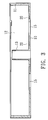
- FIG. 3 is a cross-sectional view showing the first preferred embodiment of the present invention.
- FIG. 4 is an external schematic view showing the second preferred embodiment of the present invention.
- FIG. 5 is a cross-sectional view showing the second preferred embodiment of the present invention.
- FIG. 6 is a cross-sectional view showing a third preferred embodiment of the present invention.
- FIG. 7 is an external schematic view showing a fourth preferred embodiment of the present invention.
- FIG. 8 is an external schematic view showing a fifth preferred embodiment of the present invention.
- FIG. 9 is a plane view showing a sixth preferred embodiment of the present invention.
- FIG. 10 is a cross-sectional view showing the sixth preferred embodiment of the present invention.
- the present invention relates to a base design of cooling structure, including a groove disposed on the base, in which the groove is located beyond the reach of an outer diameter of a shaft tube.
- the groove design is employed to effectively prevent the impact of thermal contraction stress on the shaft tube and prevent the shaft tube from tilting to enhance the quality and the lifespan of the product.
- a first preferred embodiment of the present invention includes a base 10 , in which a containing space 12 is surrounded by a side wall 11 on the periphery of the base excluding an air outlet side 14 , an impeller and a stator set (not shown in FIGS. 2 & 3 ) and a shaft tube 13 are disposed inside the containing space 12 , the shaft tube 13 can be assembled or integrally formed on the base 10 , and a bearing is placed in a center bore of the shaft tube 13 for supporting a spindle of the impeller to rotate therein.
- the base 10 of cooling structure can be in form of a closed-type single-inlet blower or a dual-inlet blower equipped with air inlet holes 15 , in which a groove 20 is disposed on the base and is located beyond the reach of an outer diameter of the shaft tube 13 .
- the groove 20 is an annular shallow groove disposed on the base 10 to form one face of the containing space 12 .
- the groove 20 can be disposed in a range from the outer diameter of the shaft tube 13 to the air inlet holes and disposed beyond the range of the air inlet holes 15 .
- FIG. 4 and FIG. 5 A second preferred embodiment of the present invention is illustrated in FIG. 4 and FIG. 5 .
- a groove 20 is in form of an annular shallow groove and is disposed on the bottom surface of the base 10 , and the groove 20 can be disposed in a range from an outer diameter to air inlet holes 15 and disposed beyond the range of the air inlet holes 15 .
- FIG. 6 A third preferred embodiment is illustrated in FIG. 6 .
- An annular groove 20 can be disposed on a top side and a bottom side of the base 10 respectively, disposed in a range from an outer diameter of a shaft tube 13 to air inlet holes 15 and disposed beyond the range of the air inlet holes 15 .
- a groove 30 of this pattern is constituted by arranging a plurality of long-strip-like shallow grooves as a ring, can be selectively disposed on the top side and the bottom side of the base 10 respectively or on either one, can be disposed in a range from an outer diameter of a shaft tube 13 to air inlet holes 15 and can be disposed beyond the range of the air inlet holes 15 .
- a fifth preferred embodiment of the present invention is illustrated in FIG. 8 .
- a groove 30 of this pattern is constituted by arranging a plurality of long-strip-like shallow grooves to form at least two rings, can be selectively disposed on both the top side and the bottom side of the base 10 or on either one, can be disposed in a range from an outer diameter of a shaft tube 13 to air inlet holes 15 and can be disposed beyond the range of the air inlet holes 15 .
- a sixth preferred embodiment of the present invention is an axial flow cooling structure, in which its frame 40 has a base 41 therein, the base 41 is connected with the frame 40 by a plurality of ribs 42 , a shaft tube 43 is formed on the base 41 and can be assembled or integrally formed on the base 41 , grooves 20 are disposed on the base 41 , located beyond the reach of an outer diameter of the shaft tube 43 and selectively disposed on both a top and a bottom sides of the base 41 or on either one.
- the characteristics of the present invention at least include:
- the present invention provides a groove beyond the outer diameter of the shaft tube on the base, employs the groove design to effectively prevent the non-uniform contraction stress caused by difference of cooling time and temperature and to prevent the impact of the thermal contraction stress on the vertical alignment precision of the center line of the shaft tube, so as to avoid a slanted shaft tube.
Landscapes
- Engineering & Computer Science (AREA)
- Mechanical Engineering (AREA)
- General Engineering & Computer Science (AREA)
- Physics & Mathematics (AREA)
- Thermal Sciences (AREA)
- Structures Of Non-Positive Displacement Pumps (AREA)
Abstract
Description
Claims (19)
Applications Claiming Priority (3)
| Application Number | Priority Date | Filing Date | Title |
|---|---|---|---|
| TW95148824 | 2006-12-25 | ||
| TW095148824A TW200829142A (en) | 2006-12-25 | 2006-12-25 | Base design of cooling structure |
| TW95148824A | 2006-12-25 |
Publications (2)
| Publication Number | Publication Date |
|---|---|
| US20080152486A1 US20080152486A1 (en) | 2008-06-26 |
| US7857583B2 true US7857583B2 (en) | 2010-12-28 |
Family
ID=39543047
Family Applications (1)
| Application Number | Title | Priority Date | Filing Date |
|---|---|---|---|
| US11/700,115 Expired - Fee Related US7857583B2 (en) | 2006-12-25 | 2007-01-31 | Base design of cooling structure |
Country Status (2)
| Country | Link |
|---|---|
| US (1) | US7857583B2 (en) |
| TW (1) | TW200829142A (en) |
Cited By (3)
| Publication number | Priority date | Publication date | Assignee | Title |
|---|---|---|---|---|
| US20140203450A1 (en) * | 2013-01-23 | 2014-07-24 | Amtek Semiconductors Co., Ltd. | Semiconductor package and method of fabricating the same |
| US20150167678A1 (en) * | 2013-12-12 | 2015-06-18 | Sanyo Denki Co., Ltd. | Axial flow fan and series axial flow fan |
| US9234528B2 (en) | 2012-07-05 | 2016-01-12 | Sunonwealth Electric Machine Industry Co., Ltd. | Motor base |
Families Citing this family (5)
| Publication number | Priority date | Publication date | Assignee | Title |
|---|---|---|---|---|
| CN102108981B (en) * | 2009-12-28 | 2014-04-16 | 昆山广兴电子有限公司 | Radiator fan frame |
| TWI503484B (en) * | 2010-12-14 | 2015-10-11 | Delta Electronics Inc | Centrifugal fan |
| CN103900227B (en) * | 2014-03-21 | 2022-04-08 | 珠海格力电器股份有限公司 | Compressor installation chassis and have its air conditioner, dehumidifier |
| CN106999199B (en) * | 2014-12-25 | 2020-04-21 | 奥林巴斯株式会社 | medical device |
| US20190353177A1 (en) * | 2018-05-21 | 2019-11-21 | Asia Vital Components Co., Ltd. | Fan frame seat and fan thereof |
Citations (2)
| Publication number | Priority date | Publication date | Assignee | Title |
|---|---|---|---|---|
| US6616422B2 (en) * | 2001-10-09 | 2003-09-09 | Adda Corporation | Cooling fan dust structure for keeping off flying dust from entering into spindle |
| US20070222331A1 (en) * | 2006-03-27 | 2007-09-27 | Sunonwealth Electric Machine Industry Co., Ltd. | Small heat-dissipating device |
-
2006
- 2006-12-25 TW TW095148824A patent/TW200829142A/en not_active IP Right Cessation
-
2007
- 2007-01-31 US US11/700,115 patent/US7857583B2/en not_active Expired - Fee Related
Patent Citations (2)
| Publication number | Priority date | Publication date | Assignee | Title |
|---|---|---|---|---|
| US6616422B2 (en) * | 2001-10-09 | 2003-09-09 | Adda Corporation | Cooling fan dust structure for keeping off flying dust from entering into spindle |
| US20070222331A1 (en) * | 2006-03-27 | 2007-09-27 | Sunonwealth Electric Machine Industry Co., Ltd. | Small heat-dissipating device |
Cited By (5)
| Publication number | Priority date | Publication date | Assignee | Title |
|---|---|---|---|---|
| US9234528B2 (en) | 2012-07-05 | 2016-01-12 | Sunonwealth Electric Machine Industry Co., Ltd. | Motor base |
| US20140203450A1 (en) * | 2013-01-23 | 2014-07-24 | Amtek Semiconductors Co., Ltd. | Semiconductor package and method of fabricating the same |
| US9390959B2 (en) * | 2013-01-23 | 2016-07-12 | Amtek Semiconductors Co., Ltd. | Semiconductor package with stator set formed by circuits |
| US9679826B2 (en) | 2013-01-23 | 2017-06-13 | Amtek Semiconductors Co., Ltd. | Method for fabricating semiconductor package with stator set formed by circuits |
| US20150167678A1 (en) * | 2013-12-12 | 2015-06-18 | Sanyo Denki Co., Ltd. | Axial flow fan and series axial flow fan |
Also Published As
| Publication number | Publication date |
|---|---|
| US20080152486A1 (en) | 2008-06-26 |
| TWI318559B (en) | 2009-12-11 |
| TW200829142A (en) | 2008-07-01 |
Similar Documents
| Publication | Publication Date | Title |
|---|---|---|
| US7857583B2 (en) | Base design of cooling structure | |
| CN106246925B (en) | Labyrinth type machine tool spindle air curtain protection device | |
| CN101294578B (en) | Cooling fan and stator insulation sheet structure thereof | |
| US20080218018A1 (en) | Cooling fan and method of fabrication | |
| US7775767B2 (en) | Fan assembly | |
| US20110217193A1 (en) | Structural improvement of submersible cooling pump | |
| CA2517994A1 (en) | Radial fan wheel, fan unit, and radial fan arrangement | |
| US20060119195A1 (en) | Rotor device capable of dissipating heat | |
| WO2009059718A1 (en) | Side channel compressor | |
| JP2015021427A (en) | Blower fan | |
| CN106246923B (en) | Split type machine tool spindle air sealing device | |
| US8328533B2 (en) | Heat dissipation fan | |
| CN103827527A (en) | Air bearing unit | |
| US20150354585A1 (en) | Slim fan structure | |
| JP2007218101A (en) | Axial fan and housing for axial fan | |
| CN107477006A (en) | Air-supply arrangement | |
| US20080085189A1 (en) | Micro fan | |
| US20080298983A1 (en) | Fan, motor and bearing structure thereof | |
| US7938619B2 (en) | Turbo vacuum pump | |
| JP3150477U (en) | Fan and its fan wheel | |
| JP2006226211A (en) | Blower | |
| US20060269416A1 (en) | Blower and impeller structure thereof | |
| JP5751955B2 (en) | Ring-cut multistage pump | |
| CN114635872B (en) | Fan and cleaning equipment | |
| US8182219B2 (en) | Fan and bearing structure |
Legal Events
| Date | Code | Title | Description |
|---|---|---|---|
| AS | Assignment |
Owner name: SUNONWEALTH ELECTRIC MACHINE INDUSTRY CO., LTD., T Free format text: ASSIGNMENT OF ASSIGNORS INTEREST;ASSIGNORS:HORNG, ALEX;LI, TUNG CHENG;REEL/FRAME:018868/0467 Effective date: 20070105 |
|
| STCF | Information on status: patent grant |
Free format text: PATENTED CASE |
|
| FPAY | Fee payment |
Year of fee payment: 4 |
|
| AS | Assignment |
Owner name: SUNONWEALTH ELECTRIC MACHINE INDUSTRY CO., LTD., T Free format text: CHANGE OF ASSIGNEE ADDRESS;ASSIGNOR:SUNONWEALTH ELECTRIC MACHINE INDUSTRY CO., LTD.;REEL/FRAME:045837/0241 Effective date: 20180405 |
|
| MAFP | Maintenance fee payment |
Free format text: PAYMENT OF MAINTENANCE FEE, 8TH YEAR, LARGE ENTITY (ORIGINAL EVENT CODE: M1552) Year of fee payment: 8 |
|
| FEPP | Fee payment procedure |
Free format text: MAINTENANCE FEE REMINDER MAILED (ORIGINAL EVENT CODE: REM.); ENTITY STATUS OF PATENT OWNER: LARGE ENTITY |
|
| LAPS | Lapse for failure to pay maintenance fees |
Free format text: PATENT EXPIRED FOR FAILURE TO PAY MAINTENANCE FEES (ORIGINAL EVENT CODE: EXP.); ENTITY STATUS OF PATENT OWNER: LARGE ENTITY |
|
| STCH | Information on status: patent discontinuation |
Free format text: PATENT EXPIRED DUE TO NONPAYMENT OF MAINTENANCE FEES UNDER 37 CFR 1.362 |
|
| FP | Lapsed due to failure to pay maintenance fee |
Effective date: 20221228 |