US7849285B2 - Method for scheduling of storage devices - Google Patents
Method for scheduling of storage devices Download PDFInfo
- Publication number
- US7849285B2 US7849285B2 US11/968,214 US96821408A US7849285B2 US 7849285 B2 US7849285 B2 US 7849285B2 US 96821408 A US96821408 A US 96821408A US 7849285 B2 US7849285 B2 US 7849285B2
- Authority
- US
- United States
- Prior art keywords
- task
- power
- power control
- storage
- execution
- Prior art date
- Legal status (The legal status is an assumption and is not a legal conclusion. Google has not performed a legal analysis and makes no representation as to the accuracy of the status listed.)
- Expired - Fee Related, expires
Links
Images


Classifications
-
- G—PHYSICS
- G06—COMPUTING OR CALCULATING; COUNTING
- G06F—ELECTRIC DIGITAL DATA PROCESSING
- G06F3/00—Input arrangements for transferring data to be processed into a form capable of being handled by the computer; Output arrangements for transferring data from processing unit to output unit, e.g. interface arrangements
- G06F3/06—Digital input from, or digital output to, record carriers, e.g. RAID, emulated record carriers or networked record carriers
- G06F3/0601—Interfaces specially adapted for storage systems
- G06F3/0628—Interfaces specially adapted for storage systems making use of a particular technique
- G06F3/0655—Vertical data movement, i.e. input-output transfer; data movement between one or more hosts and one or more storage devices
- G06F3/0659—Command handling arrangements, e.g. command buffers, queues, command scheduling
-
- G—PHYSICS
- G06—COMPUTING OR CALCULATING; COUNTING
- G06F—ELECTRIC DIGITAL DATA PROCESSING
- G06F1/00—Details not covered by groups G06F3/00 - G06F13/00 and G06F21/00
- G06F1/26—Power supply means, e.g. regulation thereof
- G06F1/32—Means for saving power
- G06F1/3203—Power management, i.e. event-based initiation of a power-saving mode
- G06F1/3206—Monitoring of events, devices or parameters that trigger a change in power modality
- G06F1/3215—Monitoring of peripheral devices
- G06F1/3221—Monitoring of peripheral devices of disk drive devices
-
- G—PHYSICS
- G06—COMPUTING OR CALCULATING; COUNTING
- G06F—ELECTRIC DIGITAL DATA PROCESSING
- G06F1/00—Details not covered by groups G06F3/00 - G06F13/00 and G06F21/00
- G06F1/26—Power supply means, e.g. regulation thereof
- G06F1/32—Means for saving power
- G06F1/3203—Power management, i.e. event-based initiation of a power-saving mode
- G06F1/3234—Power saving characterised by the action undertaken
- G06F1/325—Power saving in peripheral device
- G06F1/3268—Power saving in hard disk drive
-
- G—PHYSICS
- G06—COMPUTING OR CALCULATING; COUNTING
- G06F—ELECTRIC DIGITAL DATA PROCESSING
- G06F3/00—Input arrangements for transferring data to be processed into a form capable of being handled by the computer; Output arrangements for transferring data from processing unit to output unit, e.g. interface arrangements
- G06F3/06—Digital input from, or digital output to, record carriers, e.g. RAID, emulated record carriers or networked record carriers
- G06F3/0601—Interfaces specially adapted for storage systems
- G06F3/0602—Interfaces specially adapted for storage systems specifically adapted to achieve a particular effect
- G06F3/0625—Power saving in storage systems
-
- G—PHYSICS
- G06—COMPUTING OR CALCULATING; COUNTING
- G06F—ELECTRIC DIGITAL DATA PROCESSING
- G06F3/00—Input arrangements for transferring data to be processed into a form capable of being handled by the computer; Output arrangements for transferring data from processing unit to output unit, e.g. interface arrangements
- G06F3/06—Digital input from, or digital output to, record carriers, e.g. RAID, emulated record carriers or networked record carriers
- G06F3/0601—Interfaces specially adapted for storage systems
- G06F3/0628—Interfaces specially adapted for storage systems making use of a particular technique
- G06F3/0629—Configuration or reconfiguration of storage systems
- G06F3/0634—Configuration or reconfiguration of storage systems by changing the state or mode of one or more devices
-
- G—PHYSICS
- G06—COMPUTING OR CALCULATING; COUNTING
- G06F—ELECTRIC DIGITAL DATA PROCESSING
- G06F3/00—Input arrangements for transferring data to be processed into a form capable of being handled by the computer; Output arrangements for transferring data from processing unit to output unit, e.g. interface arrangements
- G06F3/06—Digital input from, or digital output to, record carriers, e.g. RAID, emulated record carriers or networked record carriers
- G06F3/0601—Interfaces specially adapted for storage systems
- G06F3/0668—Interfaces specially adapted for storage systems adopting a particular infrastructure
- G06F3/067—Distributed or networked storage systems, e.g. storage area networks [SAN], network attached storage [NAS]
-
- Y—GENERAL TAGGING OF NEW TECHNOLOGICAL DEVELOPMENTS; GENERAL TAGGING OF CROSS-SECTIONAL TECHNOLOGIES SPANNING OVER SEVERAL SECTIONS OF THE IPC; TECHNICAL SUBJECTS COVERED BY FORMER USPC CROSS-REFERENCE ART COLLECTIONS [XRACs] AND DIGESTS
- Y02—TECHNOLOGIES OR APPLICATIONS FOR MITIGATION OR ADAPTATION AGAINST CLIMATE CHANGE
- Y02D—CLIMATE CHANGE MITIGATION TECHNOLOGIES IN INFORMATION AND COMMUNICATION TECHNOLOGIES [ICT], I.E. INFORMATION AND COMMUNICATION TECHNOLOGIES AIMING AT THE REDUCTION OF THEIR OWN ENERGY USE
- Y02D10/00—Energy efficient computing, e.g. low power processors, power management or thermal management
-
- Y—GENERAL TAGGING OF NEW TECHNOLOGICAL DEVELOPMENTS; GENERAL TAGGING OF CROSS-SECTIONAL TECHNOLOGIES SPANNING OVER SEVERAL SECTIONS OF THE IPC; TECHNICAL SUBJECTS COVERED BY FORMER USPC CROSS-REFERENCE ART COLLECTIONS [XRACs] AND DIGESTS
- Y02—TECHNOLOGIES OR APPLICATIONS FOR MITIGATION OR ADAPTATION AGAINST CLIMATE CHANGE
- Y02D—CLIMATE CHANGE MITIGATION TECHNOLOGIES IN INFORMATION AND COMMUNICATION TECHNOLOGIES [ICT], I.E. INFORMATION AND COMMUNICATION TECHNOLOGIES AIMING AT THE REDUCTION OF THEIR OWN ENERGY USE
- Y02D30/00—Reducing energy consumption in communication networks
- Y02D30/50—Reducing energy consumption in communication networks in wire-line communication networks, e.g. low power modes or reduced link rate
Definitions
- the present invention relates to a power-saving technology for storage system.
- the MAID technology starts or stops the disk in a unit of array groups, the array group cannot be stopped in a time zone in which if there is any access to the same array group. Therefore, in a case where plural accesses are made in different time zones, the power consumption is increased in comparison with the case that the accesses are made in the same time zone. And, to realize the power saving, the power to the time zone in which there is no access may be stopped, but the life of a physical disk might be decreased if the power is frequently turned on or off. In addition, if plural physical disks are collectively activated in a particular period, the power consumption of all the storage system in that period increases suddenly, possibly influencing on the stable operation of the system. For realization of power saving, it is necessary to pay attention to an operation performed under such a condition that a possibility of causing such a disadvantageous situation is decreased.
- the present invention is to realize power saving of the storage system even under prescribed conditions.
- the present invention has been made to solve the above problem and realizes power saving of the storage system by the following means.
- a schedule plan of optimum tasks which satisfies a condition about the time of execution of a designated task of a storage system that plural tasks are executed and is judged on the basis of total power consumption, peak power consumption, power-on or power-off frequency and the like, is developed and shown to a user for selection.
- Task execution and start/stop control of a power controlled unit are performed based on the schedule plan selected by the user. For the start/stop control, a timing of power control is received from the storage system to schedule in accordance with the execution of actual tasks. Thus, the power saving of the storage system is realized.
- FIG. 1 is a block diagram of the storage system according to a first embodiment of the invention.
- FIG. 2 is a block diagram of a memory on a storage management server according to the first embodiment of the invention.
- FIG. 3 is a flow chart showing AP task information and power control condition collection according to the first embodiment of the invention.
- FIG. 4 shows the contents of a storage configuration information table 2011 according to the first embodiment of the invention.
- FIG. 5 shows a screen example that executable time zones of individual tasks are set by a user.
- FIG. 6 shows the contents of an AP task information table 2012 according to the first embodiment of the invention.
- FIG. 7 shows an overview of an allowable peak power setting step performed by an operation management program 200 according to the first embodiment of the invention.
- FIG. 8 shows an overview of a power-off frequency setting step performed by the operation management program 200 according to the first embodiment of the invention.
- FIG. 9 is a flow chart showing schedule plan development processing according to the first embodiment of the invention.
- FIG. 10 is a flow chart showing power control schedule plan development processing according to the first embodiment of the invention.
- FIG. 11A is part one of a diagram showing a specific example of schedule plan development processing according to the first embodiment of the invention.
- FIG. 11B is part two of the diagram showing a specific example of schedule plan development processing according to the first embodiment of the invention.
- FIG. 12 is a diagram showing an AP task execution schedule table 2016 .
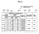
- FIG. 13 is a diagram showing a power control schedule table 2017 .
- FIG. 14 is a diagram showing a screen example for presentation and selection of an AP task execution schedule plan.
- FIG. 15A is part one of a flow chart showing AP task execution and power control processing according to the first embodiment of the invention.
- FIG. 15B is part two of the flow chart showing the AP task execution and power control processing according to the first embodiment of the invention.
- FIG. 15C is part three of the flow chart showing the AP task execution and power control processing according to the first embodiment of the invention.
- FIG. 16 is a diagram showing an AP task actual execution time table 2018 .
- FIG. 17 is a flow chart showing AP task execution schedule change processing according to the first embodiment of the invention.
- FIG. 18 is a block diagram showing a memory on a storage management server according to a second embodiment of the invention.
- FIG. 19 is a flow chart showing AP task information and power control condition collection according to the second embodiment of the invention.
- FIG. 20 shows an overview of an AP task execution information setting step performed by an operation management program 200 according to the second embodiment of the invention.
- FIG. 21A is part one of a flow chart showing the AP task execution monitoring and power control processing according to the second embodiment of the invention.
- FIG. 21B is part two of the flow chart showing the AP task execution monitoring and power control processing according to the second embodiment of the invention.
- the first embodiment creates a schedule plan to be selected by a user to manage storage system in order to achieve power saving. Details including a method of developing the schedule plan, and the like are described below.
- FIG. 1 is a block diagram showing a storage system according to the first embodiment of the invention.
- This storage system is comprised of servers 101 , a SAN (Storage Area Network) 103 , a storage system 104 , a storage management server 108 and a LAN (Local Area Network) 113 .
- servers 101 a SAN (Storage Area Network) 103
- storage system 104 a storage management server 108
- LAN Local Area Network
- the storage system 104 has a controller 105 with a power control function, power controlled units 106 , logical volumes 107 , a SAN interface 116 and a LAN interface 117 .
- the controller 105 with a power control function is a control unit for controlling input and output of data between the servers 101 and the logical volumes 107 and controlling the power to the power controlled units 106 .
- the logical volumes 107 are memory parts which store data in memory areas (storage memory areas) of the storage system 104 and configure one or plural management units for the stored data.
- the logical volumes 107 are virtually created to actually configure one or plural management units from one or plural physical disks (memory devices such as HDD (Hard Disk Drive)). In FIG. 1 , for convenience of explanation, the physical disks are omitted.
- the server 101 accesses the memory areas of the storage system 104 via the SAN 103 and recognizes the memory areas as the logical volumes 107 . At this time, it seems from the viewpoint of the server 101 that the single logical volume 107 configures plural physical disks or the plural logical volumes 107 configure a single physical disk, depending on the specifications of the logical volumes 107 .
- the power controlled unit (may be indicated as “PCU”) 106 which is subject to the power control is comprised of one or plural logical volumes 107 and a unit of power control for a power supply required for operating the physical disk.
- the power controlled units 106 have the power supply separately controlled by the controller 105 with a power control function.
- the power controlled units 106 may be configured to be subjected to the power control in a unit of the physical disk, but FIG. 1 shows that a logical volume is created from the physical disk included in the power controlled units 106 , so that it is determined that the control is performed in a unit of the logical volume. It is because optimum power saving can be realized while securing the performance of a resource when the storage system 104 is operated.
- the storage system 104 has the SAN interface 116 and is connected to the SAN 103 via the SAN interface 116 .
- the storage system 104 has the LAN interface 117 and connected to the LAN 113 via the LAN interface 117 .
- An application program (hereinafter referred to as “AP”) 102 operates on the server 101 .
- the server 101 has a SAN interface 115 and is connected to the SAN 103 via the SAN interface 115 .
- the server 101 is connected to the controller 105 with a power control function of the storage system 104 through the SAN 103 .
- the server 101 is connected to the controller 105 with a power control function through another network such as IP-SAN (Internet Protocol-Storage Area Network) or NAS (Network Attached Storage) instead of the SAN 103 .
- the server 101 has a LAN interface 114 and is connected to the LAN 113 via the LAN interface 114 .
- the AP 102 is software to execute single or plural tasks using the memory areas of the storage system 104 which are recognized as the logical volumes 107 . It is assumed in this embodiment that one AP 102 is operated on the single server 101 , but the plural APs 102 may also be operated. The task executed by the AP 102 is occasionally indicated as the “AP task”.
- the server 101 has a dummy access issuance unit 122 .
- the dummy access issuance unit 122 issues a dummy access as dummy to access the logical volumes 107 as data read only (Read only, and data writing (Write) is not performed).
- the AP 102 executes a task using the dummy access.
- the storage management server 108 has a CPU (Central Processing Unit) 109 , a memory 110 , a display unit 111 , an input unit 119 , a timer 120 , a dummy access issuance control unit 121 , a power control timing receiving unit 112 and a LAN interface 118 .
- the CPU 109 reads and executes a program stored in the memory 110 described later in FIG. 2 to perform various processings.
- the CPU 109 shows information requiring interaction with a user in various processing steps on the display unit 111 .
- the CPU 109 processes the information input through the input unit 119 through the interaction.
- the storage management server 108 is connected to the LAN 113 via the LAN interface 118 .
- the power control timing receiving unit 112 receives power control timing in the power controlled units 106 from the storage system 104 through the LAN 113 .
- the power control timing means a timing of execution of control for power-on or power-off of the individual power controlled units 106 .
- the timer 120 has a timer function to generate time information according to an instruction from the CPU 109 . Time to be generated includes the present time, the task execution start time, the task execution end time, the time when a timing of power control is received for each power controlled unit, and the like.
- the dummy access issuance control unit 121 requests the server 101 to issue a dummy access.
- the storage management server 108 may have a recording medium such as a ROM (Read Only Memory) for recording a program stored in the memory 110 .
- FIG. 2 is a block diagram of the memory on the storage management server according to the first embodiment of the invention.
- the memory 110 stores an operation management program 200 and an operation management database (hereinafter referred to as “operation management DB (Data Base)”) 201 .
- operation management DB Data Base
- the operation management program 200 is comprised of an AP task information and power control condition collecting program 2001 , an AP task execution schedule plan development/display program 2002 , an AP task execution and power control program 2003 and an AP task execution schedule change program 2004 .
- the operation management DB 201 is comprised of a storage configuration information table 2011 , an AP task information table 2012 , an allowable peak power information table 2013 , a power consumption information table 2014 , a number of power-offs table 2015 , an AP task execution schedule table 2016 , a power control schedule table 2017 and an AP task actual execution time table 2018 .
- the AP task information and power control condition collecting program 2001 collects from the storage system 104 , the servers 101 and the input unit 119 storage configuration information of the storage system 104 , information on a task performed by the AP 102 on the server 101 , information on the peak power which is information on the maximum power allowable for the storage system 104 as a whole, information on the power consumption of the each power controlled unit 106 and information on the number of power-offs of the each power controlled unit 106 and stores them in the storage configuration information table 2011 , the AP task information table 2012 , the allowable peak power information table 2013 , the power consumption information table 2014 and the number of power-offs table 2015 of the operation management DB 201 . Processing by the AP task information and power control condition collecting program 2001 and the individual pieces of information are described in detail later with reference to FIG. 3 to FIG. B.
- the AP task execution schedule plan development/display program 2002 develops power control schedule plans which are power-on or power-off schedules of the individual power controlled units 106 of the AP task execution schedule plan and storage system 104 for the task performed by the AP 102 on the server 101 and stores them in the AP task execution schedule table 2016 and the power control schedule table 2017 in the operation management DB 201 .
- the individual schedule plans developed are shown on the display unit 111 . The processing by the AP task execution schedule plan development/display program 2002 and the individual tables will be described in detail later with reference to FIG. 9 through FIG. 14 .
- the AP task execution and power control program 2003 requests the server 101 to execute the task to be performed by the AP 102 . It also requests the controller 105 with a power control function to power on or power off the power controlled unit. Processing by the AP task execution and power control program 2003 will be described in detail later with reference to FIG. 15 and FIG. 16 .
- the AP task execution schedule change program 2004 updates the schedule on the basis of the timing of the power control received by the power control timing receiving unit 112 . Using the timer 120 , the AP task execution schedule change program 2004 obtains the task execution start time and end time and determines the actual execution time of the task. The determined actual execution time is stored in the AP task actual execution time table 2018 . Where the power control timing is received, the actual execution time of the task is obtained from the AP task actual execution time table 2018 . The processing by the AP task execution schedule change program 2004 will be described in detail later with reference to FIG. 16 and FIG. 17 .
- This processing is classified into those performed by the AP task information and power control condition collecting program 2001 , the AP task execution schedule plan development/display program 2002 , the AP task execution and power control program 2003 and the AP task execution schedule change program 2004 which configure the operation management program 200 and described.
- the each processing is described in detail below.
- FIG. 3 is a flow chart showing the AP task information and power control condition collection processing performed by the AP task information and power control condition collecting program 2001 according to the first embodiment of the invention. This flow chart is described below with reference to FIG. 4 through FIG. 8 .
- the operation management program 200 collects the AP task information and power control condition on an occasion of a change of the configuration of the storage system 104 , an increase or decrease in the task performed by the server 101 , a change (input of a change through the input unit 119 ) in a power control plan of the storage system 104 by a user, or the like.
- the operation management program 200 executes a storage configuration information collecting step (step S 301 ).
- the storage configuration information is collected from the storage system 104 and stored in the storage configuration information table 2011 .
- the storage configuration information is information indicating a capacity possessed by the logical volumes 107 of the storage system 104 in order to store data and its belonging power controlled unit 106 .
- FIG. 4 shows the contents of the storage configuration information table 2011 .
- the storage configuration information table 2011 includes as fields a volume ID (identification) 2011 A for uniquely identifying volumes (indicating logical volumes in this embodiment), a capacity 2011 B indicating a capacity of a volume storable area, and an assigned power controlled unit ID 2011 C of an identifier of the assigned power controlled unit.
- a capacity of the logical volume identified as “0:01” is 10 GB (Giga-Byte) by collecting the storage configuration information from the storage system 104 and the assigned power controlled unit is identified as “1-1-1”
- the value “0:01” volume name
- the value “10 GB” is stored in the field of the capacity 2011 B
- the value “1-1-1” is stored in the assigned power controlled unit ID 2011 C in the storage configuration information table 2011 .
- the operation management program 200 executes an AP task executable time zone setting step (step S 302 ).
- the AP task executable time zone setting step the task name of the task to be executed by the AP 102 on the server 101 is obtained from the each server 101 .
- a screen used by the user to set the executable time bands of the individual tasks is shown on the display unit 111 according to the obtained task names.
- FIG. 5 shows a screen example used by the user to set the executable time zones of the individual tasks.
- a time zone executable for each task can be set as one section per day.
- the screen shows a table including the columns such as “task name”, “designated time” and “task executable time zone”.
- the task names obtained from the server 101 are sequentially indicated as “task A”, “task B”, . . . .
- time zones in which the tasks indicated in the column of “task name”, which are designated as executable at the present moment are indicated.
- the time zone of the task A designated at the present moment is “17:00 to 6:00” in FIG. 5 .
- a box is provided for each task name so that the user can input through the input unit 119 a time zone in which the task to be set can be executed.
- the user inputs start and end times of the section indicating the time zone into the box. For example, the start time of the task A executable time zone is input as “17:00” and its end time as “6:00” in FIG. 5 .
- Another screen example may be one on which another period or plural executable time zones may be set for a single task.
- a screen may be designed to allow setting, for example, two time zones in one week.
- the operation management program 200 stores the executable time zone input on the screen into the AP task information table 2012 .
- FIG. 6 shows the contents of the AP task information table 2012 .
- the AP task information table 2012 includes as fields a task name 2012 A which is executed by the AP 102 on the server 101 , a use volume ID 2012 B which identifies a volume used by a task, a start time 2012 C of a task executable time zone, an end time 2012 D of the task executable time zone and a required time 2012 E which is a time required to execute a task for each volume used by the task.
- the task name 2012 A stores the task name obtained from the server 101 in this step.
- the use volume ID 2012 B stores the ID of the volume used by the task obtained from the server 101 .
- the start time 2012 C and the end time 2012 D store the values input by the user on the screen for setting the task executable time zones (see FIG. 5 ).
- the required time 2012 E is stored by connecting the use volume ID 2012 B and the volume ID 2011 A of the storage configuration information table 2011 (see FIG. 4 ) to obtain a capacity of a use volume and estimating the execution time from the obtained capacity.
- the execution time is estimated from the capacity, but the (actual) execution time may be calculated by, for example, actually monitoring the execution of a task which is performed by the AP 102 on the server 101 to obtain the start and end times of the task from the timer 120 .
- the task management information indicating which logical volume 107 is used to execute the task is generated for the individual tasks.
- FIG. 6 is described specifically. It is assumed that the use volume IDs of the logical volumes 107 used for the task A are “0:01” and “0:04”, and the task executable time zone is set to be “17:00 to 6:00” by the user through the input unit 119 .
- a capacity for the logical volumes of “0:01” and “0:04” is “10 GB” by referring to the capacity 2011 B of the storage configuration information table 2011 (see FIG. 4 ), so that the execution time becomes one hour for both of them.
- execution time is estimated to be one hour for the capacity of 10 GB, and execution time is estimated to be two hours for the capacity of 20 GB.
- a value “task A” is stored in the field of the task name 2012 A
- values “0:01” and “0:04” are stored in the field of the use volume ID 2012 B
- a value “17:00” is stored in the field of the start time 2012 C
- a value “6:00” is stored in the field of the end time 2012 D
- values “one hour” (corresponding to “0:01”) and “one hour” (corresponding to “0:04”) are stored in the field of the required time 2012 E.
- FIG. 7 shows an overview of the allowable peak power setting step performed by the operation management program 200 .
- the operation management program 200 shows on the display unit 111 a setting screen used by the user to set the allowable peak power information.
- the allowable peak power which is allowable for the power consumption of each power controlled unit 106 and the storage system 104 as a whole can be set.
- the “allowable” means that the storage system 104 can be operated stably.
- the screen shows a table having columns of “power controlled unit” and “power consumption (kW)”, and boxes in which allowable peak power values can be set through the input unit 119 .
- the unit names of power controlled units obtained from the storage system 104 are sequentially indicated as “1-1-1”, “1-2-1”, . . . in the “power controlled unit” column.
- the “power consumption (kW)” column is provided with the boxes in which the values of power consumed by the power controlled unit indicated in the “power controlled unit” column can be set through the input unit 119 .
- the power consumption (kW) by the power controlled unit identified as “1-1-1” is input as “10” and an allowable peak power value (kW) is input as “30” in FIG. 7 .
- the operation management program 200 stores the power consumption of each power controlled unit input on the screen and the allowable peak power which is allowable for the storage system 104 as a whole into the allowable peak power information table 2013 and the power consumption information table 2014 , respectively.
- the allowable peak power information table 2013 includes as fields a subject storage system name 2013 A on which the allowable peak power is set and a set allowable peak power 2013 B.
- the device name e.g., “device 1” of the storage system configuring the storage system of this embodiment is stored in this step.
- a value e.g., “30 kW” input by the user on the setting screen (see FIG. 7 ) is stored in the field of the allowable peak power 2013 B.
- the power consumption information table 2014 includes as fields a power controlled unit ID 2014 A which is an identifier of the power controlled units 106 on which the power consumption is set and a power consumption 2014 B which is the power consumption set by the user on the screen for setting the allowable peak power information.
- the unit name (e.g., “1-1-1”) of the power controlled unit is stored in this step.
- the value (e.g., “10 kW”) input by the user is stored for each power controlled unit into the field of the power consumption 2014 B on the setting screen (see FIG. 7 ).
- the power consumption of the individual power controlled units 106 is obtained when the user inputs through the input unit 119 , but it may also be obtained by providing the storage management server 108 with a means for monitoring the power consumption of the power controlled units 106 .
- FIG. 8 shows an overview of the number of power-offs setting step performed by the operation management program 200 .
- the operation management program 200 shows on the display unit 111 the setting screen used by the user to set the number of power-offs.
- a limit value of the number of power-offs per day of the each power controlled unit 106 can be input.
- the screen shows columns of “power controlled unit” and “number of power-offs (times/day)”.
- the unit names of the power controlled units obtained from the storage system 104 are sequentially indicated as “1-1-1”, “1-2-1”, . . . .
- the column of “number of power-offs (times/day)” is provided with boxes in which values of the number of power-offs of the power controlled unit indicated in the column of “power controlled unit” can be set through the input unit 119 .
- the number of power-offs (times/day) of the power controlled unit identified as “1-1-1” is input as “1” in FIG. 8 .
- the operation management program 200 stores the number of power-offs of the each power controlled unit input on the screen into the number of power-offs table 2015 .
- the number of power-offs table 2015 includes as the fields a power controlled unit ID 2015 A which is an identifier of the power controlled units 106 on which the number of power-offs is set and a number of power-offs 2015 B which is the number of power-offs set on the screen used by the user to set the number of power-offs.
- the unit name (e.g., “1-1-1”) of the power controlled unit is stored in this step.
- the value (e.g., “one time”) input for the each power controlled unit on the setting screen by the user is stored into the field of the number of power-offs 2015 B (see FIG. 8 ).
- FIG. 9 is a flow chart showing schedule plan development processing performed by the schedule plan development/display program 2002 according to the operation management program 200 of the first embodiment of the invention.
- the AP task execution and power control are scheduled to satisfy the above conditions.
- this schedule plan development processing is performed when the user instructs the development of the schedule plan through the input unit 119 .
- a schedule plan is developed with the number of AP tasks to be executed simultaneously (hereinafter referred to as “number of concurrently executing AP tasks”) in the developed schedule plan determined to be 1 (step S 901 ).
- the number of concurrently executing AP tasks indicates that the schedule plan to be developed includes at least one combination of tasks to be executed at the same time by that number.
- step S 902 a combination of execution orders of executable AP tasks is determined by the number of concurrently executing AP tasks of the step S 901 .
- the start and end times of the executable time zone of the each AP task are obtained from the field of the start time 2012 C and the field of the end time 2012 D by referring to the AP task information table 2012 (see FIG. 6 ), and the combination of the execution orders when executed in the executable time zone is determined.
- step S 903 it is judged whether there is a combination determined in the step S 902 (step S 903 ). If judged “No”, the procedure goes to step S 906 , and if judged “Yes”, the procedure goes to step S 904 . First, the shift to the step S 904 will be described assuming that it was judged “Yes”.
- the combinations created in the step S 902 are arranged in the AP task execution order in the executable time zone of the individual AP tasks, and the AP task execution schedule plan is developed from the combinations of the AP tasks arranged.
- the required time of each AP task per volume is obtained from the field of the required time 2012 E by referring to the AP task information table 2012 (see FIG. 6 ), and those other than AP tasks to be executed at the same time are arranged not to be executed during the execution time of the AP tasks.
- they are arranged to be close to each other in the executable time zones of the individual AP tasks so that there is no time when any AP task is not executed as much as possible.
- step S 905 the number of concurrently executing AP tasks is incremented (1 is added) (step S 905 ).
- the procedure goes to the step S 902 again.
- the processings from the step S 902 to step S 905 are sequentially repeated for the cases that the number of concurrently executing AP tasks is 2, 3, . . . , a combination of the AP task execution orders of the individual cases is determined, and the AP task execution schedule plan is developed according to the combination.
- step S 903 it is assumed that the judgment is “No” when the presence of the combination developed in the step S 902 is judged (step S 903 ), the procedure moves to the step S 906 . If the number of concurrently executing AP tasks exceeds the number of the AP tasks configuring the combination, namely the number of the task names stored in the field of the task name 2012 A of the AP task information table 2012 , such a combination is not achievable, and it is judged in the step S 903 that there is not a combination (“No”), and the procedure moves to the step S 906 .
- a power control schedule plan is determined so that the condition of the number of power-offs of the each power controlled units 106 is satisfied and the power-off time becomes largest for the AP task execution schedule plan of each combination of execution orders created in the step S 904 .
- the number of power-offs of the each power controlled unit 106 is obtained from the field of the number of power-offs 2015 B with reference to the number of power-offs table 2015 (see FIG. 8 ). Therefore, even if the AP task is not executed in a certain period of a certain power controlled unit, the life of the physical disk is taken into consideration if the number of power-offs is exceeded, and the power control schedule plan is developed so as to activate the power.
- FIG. 10 is a flow chart showing the power control schedule plan development processing according to the first embodiment of the invention.
- a loop processing to repeat from step S 1002 to step S 1005 is executed for the each power controlled unit (step S 1001 ).
- a nonexecution time zone which is a nonexecution time zone of the AP task is obtained in the subject power controlled unit from the AP task execution schedule plan developed in the step S 904 (see FIG. 9 ).
- step S 1003 the nonexecution time zones of the AP task obtained in the step S 1002 are rearranged by sorting in decreasing order of time.
- step S 1004 the period of the number of power-offs is sequentially selected from the period having a longer nonexecution time zone of the AP tasks rearranged in the step S 1003 , and the selected period is determined as “power-off period”.
- the period other than the power-off period selected in the step S 1004 is determined to be “power-on period”. After the each period is determined as described above, the power control schedule plan for the subject power controlled unit is developed.
- This processing is terminated after the power control schedule plan is developed for all the power controlled units.
- the task to perform the dummy access is performed in an interval shorter than a prescribed period before the storage system 104 is powered off.
- the dummy access issuance control unit 121 instructs the dummy access issuance unit 122 the issue of a dummy access and the interval of dummy accesses performed by the task.
- step S 907 the peak power is determined for the power control schedule plan developed in the step S 906 , and a power control schedule plan which does not satisfy the allowable peak power which is the upper limit of the peak power is excluded.
- the peak power is determined by a total sum of power consumption of the power controlled units 106 which are simultaneously active in a prescribed period.
- the power consumption of the each power controlled unit 106 is obtained from the field of the power consumption 2014 B with reference to the power consumption information table 2014 (see FIG. 7 ).
- the allowable peak power of the storage system 104 as a whole is obtained from the field of the allowable peak power 2013 B with reference to the allowable peak power information table 2013 (see FIG. 7 ).
- step S 908 the total power consumption of the individual power controlled units is determined from the power control schedule plan developed in the step S 906 .
- the total power consumption is determined by a total sum of the products of the power consumption of the individual power controlled units 106 and the total activation time.
- the power consumption of the each power controlled unit 106 is obtained from the field of the power consumption 2014 B with reference to the power consumption information table 2014 (see FIG. 7 ).
- the total activation time of the individual power controlled units 106 is obtained from the power control schedule plan developed in the step S 906 .
- step S 909 the AP task execution schedule plan and the power control schedule plan developed from the step S 901 to the step S 906 are respectively stored in the AP task execution schedule table 2016 and the power control schedule table 2017 .
- the peak power determined in the step S 907 and the total power consumption determined in the step S 908 are used as evaluation value for evaluation of the schedule plan developed by the schedule plan development processing.
- This evaluation value is shown together with the schedule plan to be shown so to be selected by the user. Referring to the shown evaluation value, the user can easily select a schedule plan optimum for power saving on the basis of the storage environmental states.
- the storage management server 108 can show the schedule plan by appropriately rearranging in, for example, ascending order of the total power consumption or ascending order of the peak power.
- FIG. 12 is a diagram showing the AP task execution schedule table 2016 .
- the AP task execution schedule table 2016 includes as fields a plan 2016 A which is a name of the AP task execution schedule plan, a task 2016 B which is a task name having performed the scheduling, a start time 2016 C which is a start time of the task execution time of the scheduled task and an end time 2016 D which is an end time of the task execution time of the scheduled task.
- FIG. 12 will be described specifically.
- all the tasks (task A, task B, task C and task D) stored in the AP task information table 2012 (see FIG. 6 )
- all realizable AP task execution schedule plans are developed.
- the plans are sequentially developed as “plan 1”, “plan 2”, . . . and stored in the field of the plan 2016 A. Focusing on “plan 3”, the values of “task A”, “task B”, “task C” and “task D” are stored as task names of the subject tasks in the fields of the task 2016 B.
- values of “1:00”, “23:00”, “0:00” and “3:00” are stored as start times of the tasks in the fields of the start time 2016 C.
- values of “2:00”, “2:00”, “1:00” and “4:00” are stored as the end times of the tasks in the fields of the end time 2016 D.
- FIG. 13 is a diagram showing the power control schedule table 2017 .
- the power control schedule table 2017 includes as fields a plan 2017 A which is a name of a power control schedule plan, a power controlled unit ID 2017 B which uniquely shows a power controlled unit having performed the scheduling, a start-up time 2017 C which is a start-up time of a power-on period of the each scheduled power controlled unit 106 , a power-off time 2017 D which is a power-off time of a power-off period of the each scheduled power controlled unit 106 , a number of power-offs 2017 E which is a number of power-offs of the each scheduled power controlled units 106 , total power consumption 2017 F which is the total power consumption of the each developed power control schedule plan, and peak power 2017 G which is the peak power of the each developed power control schedule plan.
- FIG. 13 is described below specifically.
- the power control schedule plan is developed.
- the values of the “plan 1”, the “plan 2”, the “plan 3 ”, . . . which are all the plans stored in the fields of the plan 2016 A are stored in the fields of the plan 2017 A.
- values of “1-1-1”, “1-2-1” and “1-3-1” are stored as power controlled unit IDs which uniquely show the power controlled units (see the storage configuration information table 2011 of FIG.
- the same values (“one time” for power controlled units indicated by “1-1-1”, “1-2-1”, “1-3-1”) as those stored in the number of power-offs table 2015 (see FIG. 8 ) for the individual power controlled units are stored.
- a value of “100 kW” is stored as the total power consumption determined in the step S 908 .
- a value of “30 kW” is stored as the peak power possibly produced in the power-on period determined in the step S 1005 .
- the individual AP tasks have a task executable time zone (see the AP task information table 2012 of FIG. 6 ).
- the volume used by the each AP task uses each power controlled unit (PCU).
- the each AP task has an execution time required for execution.
- the “task A” in FIG. 11A has a time zone executable between 17:00 and 6:00 and uses the power controlled units 1-1-1 and 1-2-1.
- a necessary time for execution of the task A is one hour (1 h).
- a combination of the execution order of the executable AP tasks is determined. The combination is determined by sequentially increasing the number of concurrently executing AP tasks from 1.
- a combination when the number of concurrently executing AP tasks is 2 is determined.
- the combination of ⁇ [task B, task C], task A, task D ⁇ ( 1101 ) in FIG. 11A indicates a combination that the task B and the task C are executed at the same time, then the task A is executed, and the task D is executed last.
- a combination such as ⁇ [task D, task C], [task B, task A] ⁇ ( 1102 ) is excluded because it is unexecutable in the task executable time zone of the individual AP tasks (task executable time zone “3:00 to 6:00” of the task D is present behind an executable time zone “18:00 to 1:00” of the task B).
- a combination is determined with all the numbers of concurrently executing AP tasks having the combinations.
- the AP task execution schedule plan is developed from the determined combination. At this time, the execution time between the AP tasks is made closer for arrangement within the task executable time zone of the each AP task.
- FIG. 11B shows an example of developing a power control schedule plan by arranging in order of ⁇ [task B, task C], task A, task D ⁇ which are mutually approached in the task executable time zone of the each AP task.
- those not satisfying the allowable peak power are excluded from the developed power control schedule plan (see the step S 907 in FIG. 9 ).
- a power control schedule plan is developed so that the condition of the number of power-offs of the each power controlled unit is satisfied, and the power-off time becomes largest.
- a power control schedule plan is developed so that the upper limit 1 of the number of power-offs of the each power controlled unit is satisfied, and the power-off period becomes longest in FIG. 11B .
- FIG. 11B shows an example of developing a power control schedule plan by arranging in order of ⁇ [task B, task C], task A, task D ⁇ which are mutually approached in the task executable time zone of the each AP task.
- those not satisfying the allowable peak power are excluded from the developed power control schedule plan (see the step
- the power controlled unit 1-1-1 has the upper limit 1 of the number of power-offs and the longest period of from 4:00 to 1:00 as the period of task nonexecution, so that it is stopped during this period. Conversely, it is activated for a period of from 1:00 to 4:00. Therefore, the power controlled units 1-1-1, 1-2-1 and 1-3-1 are activated for the periods from 1:00 to 4:00, from 23:00 to 2:00 and from 23:00 to 1:00 respectively in FIG. 11B .
- a task of performing a read-only dummy access is registered in the power control schedule plan. For example, a task to perform a dummy access between 2:00 and 3:00 in the power controlled unit 1-1-1 is registered in FIG. 11B . As described above, the AP task execution schedule and the power control schedule of the power controlled unit are developed.
- a schedule plan which satisfies the task executable time zone of the AP task required for the AP task, allowable peak power which is allowed by the storage system 104 as a whole as a condition of power control, and the limit value of the number of power-offs per day of the each power controlled unit 106 , can be developed.
- FIG. 14 is a diagram showing a screen example for presentation and selection of the AP task execution schedule plan which is shown by the display unit 111 according to the AP task execution schedule plan development/display program 2002 of the first embodiment of the invention.
- This screen shows a table having columns of “task execution schedule”, “power control schedule”, “total power consumption” and “peak power” for the schedule plans indicated as “plan 3” and “plan 1” by obtaining the schedule plans developed by the schedule plan development processing of FIG. 9 from the AP task execution schedule table 2016 of FIG. 12 and the power control schedule table 2017 of FIG. 13 .
- the column of “power control schedule” also includes a table classified into columns of “power controlled unit”, “power-on period” and “number of power-offs”.
- the schedule plans are rearranged in view of the power consumption and shown in the rearranged order.
- the user can select the AP task execution schedule plan and the power control schedule plan to decrease the power consumption.
- the screen is shown with rearrangement made according to the total power consumption or peak power or the number of power-offs of the individual schedule plans.
- the schedule plans are rearranged and shown in ascending order of the total power consumption.
- the total power consumption of the “plan 3” is “100 kW”, and that of the “plan 1” is “120 kW”. Therefore, the “plan 3” and the “plan 1” are shown in this order in FIG. 14 .
- the AP task execution and power controlled unit is controlled on the basis of the schedule plan selected by the user through the input unit 119 on the screen.
- the “plan 3” is selected by using a radio button.
- FIG. 15A , FIG. 15B and FIG. 15C are flow charts showing an AP task execution and power control processing performed by the AP task execution and power control program 2003 according to the operation management program 200 of the first embodiment of the invention.
- This processing is executed by the operation management program 200 on the basis of the schedule plan selected by the user through the input unit 119 on a screen for presentation and selection of the AP task execution schedule plan of FIG. 14 .
- this processing is performed by the operation management program 200 when the selection by the user is completed on the screen for presentation and selection of the AP task execution schedule plan of FIG. 14 .
- an AP task execution flag indicating whether the AP task, which corresponds to the plan stored in the AP task execution schedule table 2016 (see FIG. 12 ) and is selected by the user, is executing or not and a power controlled unit activation flag indicating whether a power controlled unit to which a volume used by the AP task belongs is being activated or not are set to FALSE (step S 1401 ).
- the AP task execution flag is “TRUE” when the AP task is being executed and “FALSE” when it is not being executed.
- the power controlled unit activation flag is “TRUE” when the power controlled unit is activating, and “FALSE” when it is not.
- the present time is obtained from the timer 120 (step S 1402 ).
- step S 1403 it is judged whether the unexecuted AP tasks include a task which is to be started earlier than the present time. Namely, it is judged whether the AP task execution flag set in the step S 1401 is FALSE and the AP task obtained in the step S 1402 and to be executed at the present time is present or not.
- the name of the AP task that the AP task execution flag is FALSE is obtained from the AP task execution schedule table 2016 (see FIG. 12 ).
- the AP task execution schedule table 2016 (see FIG. 12 ) is referred to by the name of the obtained AP task to judge whether or not there is an AP task that the start time obtained from the field of the start time 2016 C is earlier than the present time.
- the AP task is an AP task to be executed, it is determined as “Yes”, and the procedure moves to step S 1404 . If there is not, the AP task is an AP task which is not executed yet, it is determined as “No”, and the procedure moves to step S 1410 . Here, it is assumed that the judgment is “Yes”, and the procedure moves to the step S 1404 .
- step S 1404 it is judged whether the upper limit of the peak power is satisfied even when the AP task which is judged to be executed in the step S 1403 is activated.
- the list of the names of the AP tasks that the AP task execution flag is TRUE and the list of volume IDs used by the AP task from the fields of the use volume ID 2012 B by obtaining the names of the AP tasks judged to be executed in the step S 1403 from the AP task execution schedule table 2016 (see FIG. 12 ) and referring to the AP task information table 2012 (see FIG. 6 ) by the name of the AP task are obtained.
- the storage configuration information table 2011 see FIG.
- the power consumption information table 2014 (see FIG. 7 ) is referred to based on the list of the assigned power controlled unit IDs to obtain the power consumption from the fields of the power consumption 2014 B in the list of the power controlled units, and a total sum of the power consumption is determined.
- the allowable peak power stored in the field of the allowable peak power 2013 B of the allowable peak power information table 2013 (see FIG. 7 ) and the total sum of the power consumption stored in the fields of the power consumption 2014 B of the list of the determined power controlled units are compared.
- step S 1405 If the total sum of the power consumption of the determined power controlled unit is smaller than the allowable peak power, it is judged “Yes”, and the procedure moves to step S 1405 , but if it is larger, it is judged “No”, and the procedure moves to step S 1410 . Here, it is assumed that the judgment is “Yes”, and the procedure moves to step S 1405 .
- the step S 1405 It is judged in the step S 1405 whether the power controlled unit to be used by the subject AP task judged to be executed in the step S 1403 is inactivated or not.
- the name of the AP task which is judged to be executed in the step S 1403 is obtained from the AP task execution schedule table 2016 (see FIG. 12 ), and the AP task information table 2012 (see FIG. 6 ) is referred to by the name of the AP task to obtain the list of the volume ID 2012 B used by the AP task from the fields of the use volume ID 2012 B.
- the storage configuration information table 2011 (see FIG.
- step S 1406 the power controlled units 106 to which the volume used by the subject AP task judged to be nonexecuted in the step S 1405 belongs is powered on.
- the list of the nonexecution power controlled unit IDs obtained in the step S 1405 is used to request the controller 105 with a power control function of the storage system 104 to power on.
- step S 1406 the power controlled unit execution flag of the power controlled units 106 activated in the step S 1406 is updated to TRUE (step S 1407 ).
- the subject AP task which is judged to be executed in the step S 1403 is executed in the step S 1408 .
- the execution of the AP task is requested to the AP 102 on the server 101 in the name of the AP task judged to be executed in the step S 1403 .
- the present time obtained in the step S 1402 is held as the execution start time of the subject AP task.
- the AP task execution flag of the AP task executed in the step S 1408 is then updated to TRUE (step S 1409 ). After this step is completed, the procedure moves to the step S 1402 again.
- step S 1410 it is judged in step S 1410 whether the AP task executed in the step S 1408 is completed.
- the execution of the AP task is asked to the AP 102 on the server 101 in the name of the AP task that the AP task execution flag is TRUE. If any of the asked AP tasks is not being executed (namely, all the asked AP tasks are completed), it is judged “Yes”, and the procedure moves to step S 1411 , and if any one of them is being executed (namely, if the asked AP task is not completed), it is judged “NO” and the procedure moves to step S 1413 .
- step S 1411 actual execution time of the subject AP task which was being executed (AP task execution flag is updated to TRUE) in the step S 1409 is updated.
- AP task execution flag is updated to TRUE
- step S 1409 a difference between the present time obtained in the step S 1402 and the execution start time set in the step S 1408 is determined as actual execution time, and the value stored in the field of an actual execution time 2018 C of the AP task actual execution time table 2018 is updated.
- FIG. 16 is a diagram showing the AP task actual execution time table 2018 .
- the AP task actual execution time table 2018 includes as fields a task name 2018 A of tasks executed by the AP 102 on the server, a use volume ID 2018 B for identification of the volumes used by the tasks, and the actual execution time 2018 C for actual execution times of the tasks.
- task actual execution time information which indicates a level of actual execution time of the each executed task is generated.
- FIG. 16 is described specifically.
- the values of task names “task A”, “task B”, “task C” and “task D” of the tasks which are the plans stored in the AP task execution schedule table 2016 (see FIG. 12 ) and corresponded with those selected by the user are stored as task names of tasks executed by the AP 102 on the server into the fields of the task name 2018 A.
- values “0:01” and “0:04” are stored as volume IDs indicating the volumes used by the task A into the fields of the use volume ID 2018 B.
- values “one hour” (corresponding to “0:01”) and “one hour” (corresponding to “0:04”) are stored according to the actual execution time determined in the step S 1411 into the fields of the actual execution time 2018 C.
- step S 1412 the AP task execution flag of the AP task which was not being executed (completed) in the step S 1410 is updated to FALSE.
- the list of the volume IDs is obtained from the fields of the volume ID 2011 A included in the power controlled units 106 by referring to the storage configuration information table 2011 (see FIG. 4 ) by the IDs of the power controlled units.
- the list of the task names using the volumes is obtained from the fields of the task name 2012 A by referring to the AP task information table 2012 (see FIG. 6 ).
- the AP task execution flags of the tasks in the list of the obtained task names are checked, and if all of them are FALSE, the pertinent power controlled unit is judged as a stoppable power controlled unit, and the ID of the pertinent power controlled unit is added to the list of the stoppable power controlled units. Then, after all the power controlled units are completed, if there is a stoppable power controlled unit, it is judged “Yes”, and the procedure moves to step S 1414 , and if there is not, it is judged “No”, and the procedure moves to the step S 1402 . Here, it is assumed that the judgment is “Yes”, and the procedure moves to the step S 1414 .
- step S 1414 It is judged in the step S 1414 whether the power controlled unit judged as a stoppable power controlled unit in the step S 1413 is a power-off period based on the power control schedule.
- a start-up time and a stop time are obtained from the fields of the start-up time 2017 C of the power-on period and the fields of the stop time 2017 D for the power control schedule which is now being executed, by using the ID of the power controlled unit and referring to the power control schedule table 2017 (see FIG. 13 ).
- the pertinent power controlled unit is judged as a stopping power controlled unit, and the ID of the pertinent power controlled unit is added to the list of the stopping power controlled units.
- the procedure moves to step S 1415 , and if there is not, it is judged “No”, the procedure moves to the step S 1402 .
- the judgment is “Yes”, and the procedure moves to the step S 1415 .
- the power controlled unit judged as a stopping power controlled unit in the step S 1414 is powered off.
- the ID of the power-off unit added to the list of the stopping power controlled unit of the step S 1414 is used to request the controller 105 with a power control function of the storage system 104 to power off.
- step S 1416 the power controlled unit activation flag of the power controlled unit powered off in the step S 1415 is updated to FALSE. After this step is completed, the procedure moves to the step S 1402 again.
- the task execution and the power control can be executed based on the schedule plan.
- FIG. 17 is a flow chart showing AP task execution schedule change processing performed by the AP task execution schedule change program 2004 according to the operation management program 200 of the first embodiment of the invention.
- the operation management program 200 receives a notice of power-off of the power controlled unit from the storage system 104 in step S 1601 .
- an ID of the power controlled unit 106 to be powered off is received from the storage system 104 .
- the power control timing receiving unit 112 obtains timing (timing of power-off) of the power control from the notice.
- the notice from the storage system 104 is performed after it is checked by the storage system 104 that the power controlled unit is not operating for a prescribed period.
- step S 1602 the actual time spent for execution of the task is obtained.
- the actual execution time is obtained from the fields of the actual execution time 2018 C by referring to the AP task actual execution time table 2018 (see FIG. 16 ) of each AP task.
- step S 1603 the required time of the task is updated.
- the actual execution time obtained in the step S 1602 is used to update the value of the required time (the required time estimated according to the capacity of the used volume) stored in the fields of the required time 2012 E in the AP task information table 2012 (see FIG. 6 ) to its actual execution time.
- step S 1604 the schedule plan development processing shown in FIG. 9 is executed based on the information (information determined from the AP task information table 2012 in which the actual execution time is stored (see FIG. 6 )) changed in the step S 1603 .
- step S 1604 After the step S 1604 is completed, the AP task execution schedule change processing is completed.
- the schedule can be changed dynamically in accordance with the execution of the actual AP task.
- the AP task execution and power control processing ( FIG. 15A through FIG. 15C ) which is performed by the AP task execution and power control program 2003 according to the operation management program 200 is performed, so that the execution of the AP task and the execution of the power control can be performed dynamically in accordance with the execution of the actual AP task.
- the first embodiment provides the following effects. Specifically, there is produced effects that optimum power saving of the storage system which execute plural tasks can be realized under the prescribed conditions such as the task executable time zone, the total power consumption, the peak power and the number of power-on or power-off times by performing the power control by the power controlled unit to which the logical volume belongs.
- a schedule plan with attention paid to the task execution schedule and the power control schedule is developed and shown to the user, so that the user can select a convenient schedule plan considering the operating conditions of the storage system.
- the schedule plan can be changed dynamically based on the timing when the power control is performed, and another task can be executed and the power supply can be controlled in accordance with the executed task.
- the scheduling efficiency is increased.
- the second embodiment covers an example of a storage system that the power saving is realized by scheduling more simply and performing the task execution and the power control.
- the optimum schedule plan to realize the power saving of the task was decided through the interaction with the user.
- This embodiment has a characteristic different from the first embodiment that the scheduling to realize the power saving is performed without the user knowing. Therefore, this embodiment has an advantage that it is easy to conform to a task which does not have an obvious executable time zone, a task of which executable time zone cannot be clearly defined by the user, or tasks which do not depend on the execution order of the tasks.
- the second embodiment is described mainly on the differences from the first embodiment.
- FIG. 18 is a block diagram showing a memory on a storage management server according to the second embodiment of the invention. It is different from the first embodiment of the invention on the points that the operation management program 200 does not include the AP task execution schedule plan development/display program 2002 , the AP task execution and power control program 2003 and the AP task execution schedule change program 2004 but includes an AP task execution monitoring program 2005 , and the operation management DB 201 does not include the allowable peak power information table 2013 , the power consumption information table 2014 , the number of power-offs table 2015 , the AP task execution schedule table 2016 and the power control schedule table 2017 , but includes an AP task execution information table 2019 (see FIG. 2 ).
- the AP task information table 2012 does not have values of start and end times stored in the fields of the start time 2012 C of the executable time zone and the fields of the end time 2012 D.
- the AP task information and power control condition collecting program 2001 is different from the first embodiment on the points that peak power information which is information on the maximum power allowable for the storage system 104 as a whole and the number of times of power-offs of the power controlled units 106 are not collected, and the AP task execution information is collected and stored in the AP task execution information table 2019 . Details of processing of the AP task information and power control condition collecting program 2001 will be described later with reference to FIG. 19 and FIG. 20 .
- the AP task execution monitoring program 2005 monitors the AP task being executed by the AP 102 on the server 101 and requests the AP 102 of the server 101 to execute the AP task. Details of the processing of the AP task execution monitoring program 2005 will be described later with reference to FIG. 21 .
- the AP task execution information table 2019 includes information indicating AP task execution states. The contents of the AP task execution information table 2019 are described later with reference to FIG. 20 .
- Processing of the storage system according to the second embodiment of the invention is described below. For description, this processing is classified to those performed by the AP task information and power control condition collecting program 2001 and the AP task execution monitoring program 2005 which configure the operation management program 200 . Details of each processing are described below.
- FIG. 19 is a flow chart showing the AP task information and power control condition collection processing performed by the AP task information and power control condition collecting program 2001 according to the operation management program 200 of the second embodiment of the invention. This flow chart is described below with reference to FIG. 19 and FIG. 20 .
- the storage configuration information collecting step S 301 is similar to that of the first embodiment and its description is omitted (see FIG. 3 ).
- the operation management program 200 executes an AP task execution information setting step (step S 1801 ).
- the operation management program 200 obtains from the each server 101 the task name of the task executed by the AP 102 on the server 101 in order to collect the AP task information. Based on the obtained task name, a screen used by the user to set the completion intervals of the individual tasks is shown on the display unit 111 .
- the “completion interval” corresponds to the completion cycle of each task and means the longest time between the completion of a certain task and the next completion of that task.
- the each task is reexecuted in the time falling in the completion interval from the completion of the execution. Namely, the completion interval of the task is used as a trigger to execute the individual tasks. For example, if the task to be executed is backup processing of the storage system, this completion interval corresponds to RPO (Recovery Point Object).
- FIG. 20 shows an overview of an AP task execution information setting step performed by the operation management program 200 according to the second embodiment of the invention.
- FIG. 20 shows a screen example that the user sets the completion interval of each task, and the task is scheduled and executed while satisfying the completion interval set on this screen.
- This screen shows a table having a column “task name” and a column “task completion interval”, and the column “task completion interval” is provided with boxes into which the user can input so as to set a task completion interval of each task.
- the operation management program 200 stores the completion interval input on the screen into the fields of a completion interval 2019 B of the AP task execution information table 2019 of FIG. 20 .
- FIG. 20 shows the AP task execution information table 2019 , and the AP task execution information table 2019 includes as fields an AP task name 2019 A which is executed by the AP 102 on the server 101 , the completion interval 2019 B which is an interval in which the AP task is completed, and a last completion time 2019 C which indicates date and time when the previous AP task was completed.
- the AP task execution information table 2019 of FIG. 20 is described specifically. Values such as task names “task A”, “task B”, “task C” and “task D” of the tasks obtained from the server 101 are stored in the fields of the task name 2019 A. When attention is paid to the task A, a value “24 hours” is stored as the completion interval input into the fields of the completion interval 2019 B of task information by the user through the input unit 119 . And, a value “2007/01/02/12:00 (12:00, Jan. 2, 2007)” obtained from the timer 120 is stored as the time when the task A is completed last time into the fields of the last completion time 2019 C of task information.
- FIG. 21A and FIG. 21B are flow charts showing AP task execution monitoring and power control processing performed by the AP task execution monitoring program 2005 according to the operation management program 200 of the second embodiment of the invention.
- step S 1901 the operation management program 200 obtains the AP task names of AP tasks which operate on the server 101 from the AP task information table 2012 (see FIG. 6 ). For the each AP task, an AP task execution flag indicating whether the AP task is being executed or not is prepared and set to FALSE. The AP task execution flag is “TRUE” when the AP task is being executed or “FALSE” when it is not being executed.
- step S 1902 the present time is obtained from the timer 120 .
- step S 1903 It is judged in step S 1903 whether there is an AP task that the completion interval is not satisfied at the present time obtained in the step S 1902 .
- a difference between the present time obtained in the step S 1902 for each AP task and the last completion time which is stored in the field of the last completion time 2019 C in the AP task execution information table 2019 (see FIG. 20 ) is determined, and the obtained difference is determined to be an elapsed time.
- the required time is obtained from the field of the required time 2012 E by referring to the AP task information table 2012 (see FIG. 6 ) for each AP task.
- step S 1904 the subject AP task which is judged that the completion interval is not satisfied in the step S 1903 is added to the execution AP task list.
- step S 1905 the AP task using a volume which belongs to the same power controlled unit as the power controlled unit, to which the volume used by the subject AP task belongs, is added to the execution AP task list.
- a list of use volume IDs of the used volumes is obtained from the fields of the use volume ID 2012 B by referring to the AP task information table 2012 (see FIG. 6 ) by the name of the AP task added to the execution AP task list.
- a list of assigned power controlled unit IDs is obtained from the fields of the assigned power controlled unit ID 2011 C by referring to the storage configuration information table 2011 (see FIG.
- a list of volume IDs belonging to the list of assigned power controlled unit IDs is obtained from the fields of the volume ID 2011 A.
- a task name using such a volume is obtained from the fields of the task name 2012 A by referring to the AP task information table 2012 (see FIG. 6 ) on the basis of the list of the assigned volume IDs, and an AP task for the obtained task name is added to the execution AP task list.
- step S 1906 the power controlled unit used by the AP task added to the execution AP task list developed through the steps up to the step S 1905 is powered on.
- the ID of the assigned power controlled unit obtained in the step S 1905 is used to request the controller 105 with a power control function of the storage system 104 to power on.
- step S 1907 the AP task included in the execution AP task list developed through the steps up to the step S 1905 is executed.
- the name of the AP task added to the execution AP task list developed through the steps up to the step S 1905 is used to request the AP 102 on the server 101 to execute the AP task.
- step S 1908 it is set to update the AP task execution flag executed in the step S 1907 to TRUE.
- step S 1909 is executed.
- the execution start time of the AP task (AP task execution flag is set to TRUE) executed in the step S 1908 is obtained from the timer 120 .
- step S 1910 It is judged in step S 1910 whether the AP task being executed is completed.
- a task name that the AP task execution flag is TRUE is obtained from the AP task information table 2012 (see FIG. 6 ).
- the obtained AP task name is used to ask the AP 102 on the server 101 to execute the AP task. If there is a completed AP task, it is judged “Yes” and the procedure moves to step S 1911 , but if there is not, it is judged “No”, and the procedure moves to step S 1902 .
- the required time of the AP task completed in the step S 1910 is updated.
- the required time is determined from a difference between the present time obtained in the step S 1902 and the execution start time obtained in the step S 1909 .
- a value stored in the field of the required time 2012 E of the subject AP task in the AP task information table 2012 is updated to the determined required time.
- step S 1912 the last completion time of the completed AP task is updated.
- the value stored in the field of the last completion time 2019 C of the subject task is updated to the obtained present time in the AP task execution information table 2019 (see FIG. 20 ).
- step S 1913 It is set in step S 1913 to update the AP task execution flag judged to have been completed in the step S 1910 to FALSE.
- step S 1914 the AP task judged to have been completed in the step S 1910 is deleted from the execution AP task list.
- step S 1915 it is judged whether the volume used by another AP task being executed belongs to the power controlled unit to which the volume used by the completed AP task belongs. Namely, it is judged whether there is an AP task being executed and using the same power controlled unit as the completed AP task.
- the list of the using volume IDs is obtained from the fields of the use volume ID 2012 B by referring to the AP task information table 2012 (see FIG. 6 ) by the name of the completed task.
- the list of the assigned power controlled unit IDs to which the volume belongs is obtained from the fields of the assigned power controlled unit ID 2011 C by referring to the storage configuration information table 2011 (see FIG. 4 ).
- the obtained assigned power controlled unit ID is used to obtain a list of volume IDs of the volumes belonging to the power controlled unit from the fields of the volume ID 2011 A in the storage configuration information table 2011 .
- the obtained list of volume IDs is used to obtain the task name using the volume ID obtained from the fields of the task name 2012 A by referring to the AP task information table 2012 (see FIG. 6 ).
- the AP task execution flag of the obtained task name is checked, and if there is at least one AP task which becomes TRUE, it is judged “Yes”, and the procedure moves to the step S 1902 , and if there is not any AP task which becomes TRUE, it is judged “No”, and the procedure moves to step S 1916 .
- step S 1916 the power controlled unit, to which the volume used by the AP task judged to have been completed in the step S 1910 belongs, is powered off.
- the list of the assigned power controlled unit IDs obtained in the step S 1915 is used to request the controller 105 with a power control function of the storage system 104 to power off.
- the AP task execution and power control can be performed while satisfying the completion interval of the AP task which is a requirement for the AP task.
- this embodiment the example of setting the completion interval of the individual AP tasks with the startup of the AP task used as a trigger was described. But, there is also another method which is started when a certain AP task is executed by the user. As in the above examples, this embodiment monitors a task execution state by determining the timing of starting the task execution. And, following the execution of a certain task, it is made possible to realize power saving by scheduling to execute another task.
- the second embodiment provides the following effects. Specifically, an effect of realizing optimum power saving is produced for a storage system that executes plural tasks, when the power control is performed by the power controlled unit to which a logical volume belongs, by executing another task to follow the execution of a specified task according to the completion interval of the tasks. Thus, a possibility of an occurrence of a situation that a task is not executed even if the power is on is decreased.
- the storage environment changes every second, so that there is a case that it is hard to equally set a task executable time zone for the individual tasks. And, it is sometimes necessary to develop a schedule plan with attention paid to execution order of the tasks that another task must be executed to execute a prescribed task. In this embodiment, it is not necessary to set the task executable time zone from the start, and since the completion of execution of a task is presumed from the completion interval, it is not necessary to pay attention to the execution order of the tasks, and the scheduling can be made easily.
Landscapes
- Engineering & Computer Science (AREA)
- Theoretical Computer Science (AREA)
- Physics & Mathematics (AREA)
- General Engineering & Computer Science (AREA)
- General Physics & Mathematics (AREA)
- Human Computer Interaction (AREA)
- Power Sources (AREA)
Abstract
Description
(2) Task execution and start/stop control of a power controlled unit are performed based on the schedule plan selected by the user. For the start/stop control, a timing of power control is received from the storage system to schedule in accordance with the execution of actual tasks. Thus, the power saving of the storage system is realized.
(3) To provide a simple task schedule plan to realize power saving by executing another task by following the execution of a particular task.
Claims (11)
Applications Claiming Priority (2)
| Application Number | Priority Date | Filing Date | Title |
|---|---|---|---|
| JP2007-216626 | 2007-08-23 | ||
| JP2007216626A JP5011028B2 (en) | 2007-08-23 | 2007-08-23 | Storage system, management apparatus, scheduling method, program, recording medium |
Publications (2)
| Publication Number | Publication Date |
|---|---|
| US20090055520A1 US20090055520A1 (en) | 2009-02-26 |
| US7849285B2 true US7849285B2 (en) | 2010-12-07 |
Family
ID=40383198
Family Applications (1)
| Application Number | Title | Priority Date | Filing Date |
|---|---|---|---|
| US11/968,214 Expired - Fee Related US7849285B2 (en) | 2007-08-23 | 2008-01-02 | Method for scheduling of storage devices |
Country Status (2)
| Country | Link |
|---|---|
| US (1) | US7849285B2 (en) |
| JP (1) | JP5011028B2 (en) |
Cited By (3)
| Publication number | Priority date | Publication date | Assignee | Title |
|---|---|---|---|---|
| US20090326728A1 (en) * | 2008-06-27 | 2009-12-31 | Sharp Laboratories Of America, Inc. | Systems and methods for controlling power usage on a device |
| US20110107341A1 (en) * | 2009-11-03 | 2011-05-05 | International Business Machines Corporation | Job scheduling with optimization of power consumption |
| US20120233419A1 (en) * | 2011-03-09 | 2012-09-13 | Hitachi, Ltd. | Computer system, method of scheduling data replication, and computer-readable non-transitory storage medium |
Families Citing this family (25)
| Publication number | Priority date | Publication date | Assignee | Title |
|---|---|---|---|---|
| US8127154B2 (en) * | 2008-10-02 | 2012-02-28 | International Business Machines Corporation | Total cost based checkpoint selection |
| CN101510117B (en) * | 2009-03-12 | 2011-05-11 | 成都市华为赛门铁克科技有限公司 | Method, apparatus and storage apparatus for controlling state of storage apparatus |
| WO2010137180A1 (en) * | 2009-05-25 | 2010-12-02 | Hitachi,Ltd. | Storage system and its power control method |
| US8468375B2 (en) * | 2009-07-15 | 2013-06-18 | Hitachi, Ltd. | Energy consumption management for storage system using upper limit value during predetermined period |
| US8239701B2 (en) * | 2009-07-28 | 2012-08-07 | Lsi Corporation | Methods and apparatus for power allocation in a storage system |
| JP4912456B2 (en) * | 2009-12-17 | 2012-04-11 | 株式会社日立製作所 | Storage apparatus and control method thereof |
| US8527800B2 (en) * | 2010-03-02 | 2013-09-03 | Solarwinds Worldwide, Llc | Method and apparatus for displaying hour by hour power level status transitions for a network device by parsing cron job strings associated with the network device |
| JP5354106B2 (en) * | 2010-08-05 | 2013-11-27 | 富士通株式会社 | Control program, control device, and control method |
| JP5984348B2 (en) * | 2011-08-23 | 2016-09-06 | ソニー株式会社 | Information processing apparatus, information processing method, and program |
| JP5704123B2 (en) * | 2012-06-11 | 2015-04-22 | 日本電気株式会社 | I/O control device, storage system, power supply control method, and computer program |
| US10345766B2 (en) * | 2012-12-11 | 2019-07-09 | Kabushiki Kaisha Toshiba | Energy management server, energy management method, and medium |
| US9727522B1 (en) * | 2012-12-14 | 2017-08-08 | Amazon Technologies, Inc. | Multi-tenant storage service object lifecycle management using transition job objects |
| US20140281606A1 (en) * | 2013-03-15 | 2014-09-18 | Silicon Graphics International Corp. | Data storage power consumption threshold |
| JP2015076060A (en) | 2013-10-11 | 2015-04-20 | 富士通株式会社 | Information processing system, control program of management device, and control method of information processing system |
| US9552229B2 (en) | 2015-05-14 | 2017-01-24 | Atlassian Pty Ltd | Systems and methods for task scheduling |
| US9639394B2 (en) * | 2015-07-13 | 2017-05-02 | At&T Intellectual Property I, L.P. | Determining life-cycle of task flow performance for telecommunication service order |
| JP6540409B2 (en) * | 2015-09-14 | 2019-07-10 | 富士通株式会社 | Storage control device, storage control program and storage control method |
| CN105320246B (en) * | 2015-09-29 | 2019-01-15 | 联想(北京)有限公司 | A kind of information processing method and electronic equipment |
| US10067798B2 (en) | 2015-10-27 | 2018-09-04 | International Business Machines Corporation | User interface and system supporting user decision making and readjustments in computer-executable job allocations in the cloud |
| US10474379B2 (en) * | 2017-01-31 | 2019-11-12 | NE One LLC | Controlled access to storage |
| CN108345510B (en) * | 2018-01-11 | 2022-02-08 | 中国人民解放军国防科技大学 | Method for automatically inspecting and detecting reliability of large-scale off-line filing system |
| CN110018906B (en) * | 2019-02-26 | 2020-11-27 | 上海丽人丽妆网络科技有限公司 | Scheduling method, server and scheduling system |
| US11579681B2 (en) * | 2019-04-08 | 2023-02-14 | Commvault Systems, Inc. | Power management of components within a storage management system |
| EP3979021A1 (en) * | 2020-09-30 | 2022-04-06 | Ricoh Company, Ltd. | Scheduling system, scheduling method, and carrier means |
| KR20240126300A (en) * | 2023-02-13 | 2024-08-20 | 삼성전자주식회사 | Electronic device resolving sudden power off |
Citations (3)
| Publication number | Priority date | Publication date | Assignee | Title |
|---|---|---|---|---|
| US20040054939A1 (en) | 2002-09-03 | 2004-03-18 | Aloke Guha | Method and apparatus for power-efficient high-capacity scalable storage system |
| US20080301474A1 (en) * | 2005-12-23 | 2008-12-04 | Nxp B.V. | Performance Analysis Based System Level Power Management |
| US7646197B2 (en) * | 2005-10-07 | 2010-01-12 | Renesas Technology Corp. | Semiconductor integrated circuit device and power consumption control device |
Family Cites Families (3)
| Publication number | Priority date | Publication date | Assignee | Title |
|---|---|---|---|---|
| JP4485370B2 (en) * | 2005-01-06 | 2010-06-23 | 三菱電機株式会社 | Parallel computing device |
| WO2006098036A1 (en) * | 2005-03-17 | 2006-09-21 | Fujitsu Limited | Power conservation control apparatus, power conservation control method, and power conservation control program |
| JP4694333B2 (en) * | 2005-09-30 | 2011-06-08 | 株式会社日立製作所 | Computer system, storage device, system management device, and disk device power control method |
-
2007
- 2007-08-23 JP JP2007216626A patent/JP5011028B2/en not_active Expired - Fee Related
-
2008
- 2008-01-02 US US11/968,214 patent/US7849285B2/en not_active Expired - Fee Related
Patent Citations (3)
| Publication number | Priority date | Publication date | Assignee | Title |
|---|---|---|---|---|
| US20040054939A1 (en) | 2002-09-03 | 2004-03-18 | Aloke Guha | Method and apparatus for power-efficient high-capacity scalable storage system |
| US7646197B2 (en) * | 2005-10-07 | 2010-01-12 | Renesas Technology Corp. | Semiconductor integrated circuit device and power consumption control device |
| US20080301474A1 (en) * | 2005-12-23 | 2008-12-04 | Nxp B.V. | Performance Analysis Based System Level Power Management |
Cited By (5)
| Publication number | Priority date | Publication date | Assignee | Title |
|---|---|---|---|---|
| US20090326728A1 (en) * | 2008-06-27 | 2009-12-31 | Sharp Laboratories Of America, Inc. | Systems and methods for controlling power usage on a device |
| US20110107341A1 (en) * | 2009-11-03 | 2011-05-05 | International Business Machines Corporation | Job scheduling with optimization of power consumption |
| US8621472B2 (en) * | 2009-11-03 | 2013-12-31 | International Business Machines Corporation | Job scheduling with optimization of power consumption |
| US8631412B2 (en) | 2009-11-03 | 2014-01-14 | International Business Machines Corporation | Job scheduling with optimization of power consumption |
| US20120233419A1 (en) * | 2011-03-09 | 2012-09-13 | Hitachi, Ltd. | Computer system, method of scheduling data replication, and computer-readable non-transitory storage medium |
Also Published As
| Publication number | Publication date |
|---|---|
| JP5011028B2 (en) | 2012-08-29 |
| US20090055520A1 (en) | 2009-02-26 |
| JP2009048583A (en) | 2009-03-05 |
Similar Documents
| Publication | Publication Date | Title |
|---|---|---|
| US7849285B2 (en) | Method for scheduling of storage devices | |
| US11762694B2 (en) | System and method of providing system jobs within a compute environment | |
| JP5324666B2 (en) | Storage system | |
| EP2195724B1 (en) | Power management of data processing resources, such as power adaptive management of data storage operations | |
| US8589932B2 (en) | Data processing workload control | |
| US10127080B2 (en) | Dynamically controlled distributed workload execution | |
| US8255715B2 (en) | Storage system and power control method thereof with mode selection defined by timeout period and power supply | |
| EP3254193B1 (en) | Dynamically controlled workload execution | |
| KR20120109533A (en) | Query Management | |
| EP3254194B1 (en) | Dynamically controlled workload execution by an application | |
| JP5287414B2 (en) | Storage system, storage power consumption reduction method, program | |
| US20060101290A1 (en) | Method for multiple scheduled computer powers-on | |
| CN112416454B (en) | Method and device for controlling disk startup | |
| JP2013257650A (en) | Input-output control device, storage system, power control method, and computer program | |
| WO2014125580A1 (en) | Apparatus management device, frequency control method, and program | |
| CN110825313A (en) | Storage system and management method for managing operation program according to time stamp |
Legal Events
| Date | Code | Title | Description |
|---|---|---|---|
| AS | Assignment |
Owner name: HITACHI, LTD., JAPAN Free format text: ASSIGNMENT OF ASSIGNORS INTEREST;ASSIGNORS:TABATA, SHUNYA;BENIYAMA, NOBUO;OKAMOTO, TAKUYA;REEL/FRAME:020305/0620 Effective date: 20071011 |
|
| FEPP | Fee payment procedure |
Free format text: PAYOR NUMBER ASSIGNED (ORIGINAL EVENT CODE: ASPN); ENTITY STATUS OF PATENT OWNER: LARGE ENTITY |
|
| STCF | Information on status: patent grant |
Free format text: PATENTED CASE |
|
| FPAY | Fee payment |
Year of fee payment: 4 |
|
| MAFP | Maintenance fee payment |
Free format text: PAYMENT OF MAINTENANCE FEE, 8TH YEAR, LARGE ENTITY (ORIGINAL EVENT CODE: M1552) Year of fee payment: 8 |
|
| FEPP | Fee payment procedure |
Free format text: MAINTENANCE FEE REMINDER MAILED (ORIGINAL EVENT CODE: REM.); ENTITY STATUS OF PATENT OWNER: LARGE ENTITY |
|
| LAPS | Lapse for failure to pay maintenance fees |
Free format text: PATENT EXPIRED FOR FAILURE TO PAY MAINTENANCE FEES (ORIGINAL EVENT CODE: EXP.); ENTITY STATUS OF PATENT OWNER: LARGE ENTITY |
|
| STCH | Information on status: patent discontinuation |
Free format text: PATENT EXPIRED DUE TO NONPAYMENT OF MAINTENANCE FEES UNDER 37 CFR 1.362 |
|
| FP | Lapsed due to failure to pay maintenance fee |
Effective date: 20221207 |