US7834932B2 - De-interlacing method - Google Patents
De-interlacing method Download PDFInfo
- Publication number
- US7834932B2 US7834932B2 US11/560,022 US56002206A US7834932B2 US 7834932 B2 US7834932 B2 US 7834932B2 US 56002206 A US56002206 A US 56002206A US 7834932 B2 US7834932 B2 US 7834932B2
- Authority
- US
- United States
- Prior art keywords
- luminance
- weighting
- sub
- interpolation
- luminance difference
- Prior art date
- Legal status (The legal status is an assumption and is not a legal conclusion. Google has not performed a legal analysis and makes no representation as to the accuracy of the status listed.)
- Expired - Fee Related, expires
Links
Images


Classifications
-
- H—ELECTRICITY
- H04—ELECTRIC COMMUNICATION TECHNIQUE
- H04N—PICTORIAL COMMUNICATION, e.g. TELEVISION
- H04N7/00—Television systems
- H04N7/01—Conversion of standards, e.g. involving analogue television standards or digital television standards processed at pixel level
- H04N7/0117—Conversion of standards, e.g. involving analogue television standards or digital television standards processed at pixel level involving conversion of the spatial resolution of the incoming video signal
- H04N7/012—Conversion between an interlaced and a progressive signal
Definitions
- the invention relates to video de-interlacingand more particularly to an video de-interlacing method considering luminance difference vectors adjacent to an interpolated pixel.
- interlaced signal such as NTSC and PAL
- video rendering systems have to generate pixel data for scan lines that are not received in time for the subsequent field update.
- This interlace-to-progressive conversion process is referred to as de-interlacing.
- Current de-interlacing methods comprise intra-field de-interlacing, motion adaptive de-interlacing, and motion compensation deinterlaceing.
- the intra-field de-interlacing uses a single field to reconstruct one progressive frame.
- EDI edge dependent interpolation
- ESA edge-based line average
- FIG. 1 illustrates directional edge interpolation using a 5 ⁇ 3 window.
- An interlaced Line L I includes interpolated pixels with unknown luminance requiring interpolation with known luminance of two candidate pixels selected from an upper line L U and lower line L L .
- F is a current interpolated pixel with unknown luminance l(F) to be interpolated with luminance of pixels selected from candidate pixels A to E and G to K
- D 2
- D 3
- , D 4
- D 5
- FIGS. 2A and 2B show an ambiguous case as shown in FIGS. 2A and 2B.
- FIG. 2A shows an original image composing lines L U , L I and L L with luminance of each pixel shown by a number.
- FIG. 2B shows an interlaced image with line L I missed.
- ELA uses directions or as the direction with highest correlation since the directional differences thereof are all
- 0. However, the direction is the correct interpolation direction even though the directional difference thereof is
- 2, greater than 0.
- the invention provides an image de-interlacing method preventing erroneous judgment of direction with highest correlation in such an ambiguous case.
- the invention provides an image de-interlacing method for estimating an interpolation luminance of an interpolated pixel.
- a plurality of first and second candidate pixels is selected respectively on upper and lower lines adjacent to the interpolated pixel.
- a plurality of directional differences, a plurality of weighting values and a plurality of weighted directional differences are calculated, each associated with one of the first candidate pixels and one of the second candidate pixels.
- Each of the directional differences is an absolute luminance difference between the associated first and second candidate pixels.
- Each of the weighting values is determined by comparing similarity of luminance decreasing/increasing patterns near the associated first and second candidate pixels.
- Each of the weighted directional differences is determined according to the directional difference and the weighting value.
- a first selected pixel and a second selected pixel are selected respectively from the first and second candidate pixels associated with the smallest weighted directional difference.
- the interpolation luminance is obtained according to the first and second selected pixels.
- First and second luminance difference vectors are used for convenience to define mathematically luminance decreasing/increasing patterns near the associated first and second candidate pixels. More specifically, each of the weighting values is determined by comparing a first luminance difference vector of a first weighting region with a second luminance difference vector of a second weighting region. The first and second weighting regions respectively reside on the upper and lower lines and comprise the associated first and second candidate pixels. Each element of the first and second luminance difference vectors is respectively determined according to luminance difference between two adjacent pixels associated with the elements in the first and second weighting regions
- FIG. 1 illustrates conventional directional edge interpolation using a 5 ⁇ 3 window
- FIGS. 2A and 2B show an ambiguous case in conventional directional edge interpolation of FIG. 1 ;
- FIG. 3 is a flowchart of an image de-interlacing method in accordance with an embodiment of the invention.
- FIG. 4 illustrates selection of first and second candidate pixels of FIG. 3 ;
- FIG. 5 illustrates 25 directions associated of FIG. 3 ;
- FIG. 6 illustrates first and second luminance vectors of first and second weighting regions of FIG. 3 .
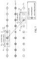
- FIG. 7 illustrates first and second sub-luminance vectors of first and second sub-weighting regions of FIG. 3 ;
- FIG. 8 illustrates arrangement of a weighting value
- FIG. 9 illustrates arrangement of a sub-weighting value
- FIG. 10 is a flowchart illustrating acquisition of interpolation luminance of a current interpolated pixel in accordance with a first embodiment of the invention
- FIG. 11 is a flowchart illustrating acquisition of interpolation luminance of a current interpolated pixel in accordance with a second embodiment of the invention.
- FIG. 12 is a flowchart illustrating modification process of a provisional interpolation luminance to the interpolation luminance.
- luminance decreasing/increasing pattern between pixel C, D, E in line L U is similar to that between pixel G, H, I in line L L , both luminance being decreased and then increased from left to right.
- improved de-interlacing is provided in several embodiments to prevent erroneous judgment as shown in FIGS. 2A and 2B by considering not only the directional differences associated with different candidate pixels on the upper and lower lines L U and L L but also similarity of luminance decreasing/increasing patterns near the candidate pixels.
- FIG. 3 is a flowchart of an image de-interlacing method in accordance with an embodiment of the invention.
- Step 310 is described with reference to FIG. 4 as follows.
- pixels are here referred to also by p(x,y), where x and y respectively denote positions relative to the current interpolated pixel F on the X and Y axes.
- the first candidate pixels A, B, C, D, E are also referred to by p( ⁇ 2,1), p( ⁇ 1,1), p(0,1), p(1,1) and p(2,1), respectively
- the current interpolated pixel F is referred to by p(0,0)
- the second candidate pixels G, H, I, J, K are referred to by p( ⁇ 2, ⁇ 1), p( ⁇ 1, ⁇ 1), p(0, ⁇ 1), p(1, ⁇ 1) and p(2, ⁇ 1), respectively.
- Step 320 is described with reference to FIG. 5 as follows.
- N 3 (such as 19, or 25 in the figure) directional differences diff(l,m), N 3 weighting values W(l, m), and N 3 weighted directional differences DIFF(l,m), are calculated, each associated with one of directions to extending between one pixel p(l,1) among the first candidate pixels A to E and one pixel p(m, ⁇ 1) of the second candidate pixels G to K ( ⁇ 2 ⁇ l,m ⁇ 2 in FIG. 4 ).
- a first weighting region 61 includes three pixels P( ⁇ 2,1), P( ⁇ 1,1), and P(0,1) (i.e. pixels A, B, and C), and a second weighting region 62 includes three pixels P(1, ⁇ 1), P(2, ⁇ 1), and P(3, ⁇ 1) (i.e. pixels J, K, and L).
- Each element of the first luminance difference vector ⁇ tilde over (D) ⁇ U, ⁇ 1 is determined according to luminance difference between two pixels associated with the element in the first weighting region 61 .
- each element of the second luminance difference vector ⁇ tilde over (D) ⁇ L,2 is determined according to luminance difference between two pixels associated with the element in the second weighting region 62 .
- the weighting value W( ⁇ 1,2) is then determined according to similarity in signs of corresponding elements of the first and second luminance difference vectors ⁇ tilde over (D) ⁇ U, ⁇ 1 and ⁇ tilde over (D) ⁇ L,2 .
- the weighting value W( ⁇ 1,2) is determined according to at least one sub-weighting value w j ( ⁇ 1,2), where 1 ⁇ i ⁇ J and J is an integer greater than 1 and each of the sub-weighting value w j ( ⁇ 1,2) is determined according to similarity in signs of corresponding elements of a first sub-luminance difference vector ⁇ tilde over (d) ⁇ U, ⁇ 1,j and a second sub-luminance difference vector ⁇ tilde over (d) ⁇ L,2,j respectively comprising partial elements of the first and second luminance difference vectors ⁇ tilde over (D) ⁇ U, ⁇ 1 and ⁇ tilde over (D) ⁇ L,2 .
- w j sub-weighting value
- W ⁇ ( - 1 , 2 ) ⁇ 1 ⁇ j ⁇ J ⁇ ⁇ w j ⁇ ( - 1 , 2 ) + w off , wherein w off is a predetermined offset value.
- each element of the first sub-luminance difference vectors ⁇ tilde over (d) ⁇ U, ⁇ 1,1 (or ⁇ tilde over (d) ⁇ U, ⁇ 1,2 ) is determined according to luminance difference between two adjacent points in the first sub-weighting region 61 1 ( 61 2 ), and similarly, each element of the second sub-luminance difference vectors ⁇ tilde over (d) ⁇ L,2,1 (or ⁇ tilde over (d) ⁇ L,2,2 ) is determined according to luminance difference between two adjacent points in the first sub-weighting region 61 1 ( 61 2 ).
- the first and second sub-luminance difference vectors ⁇ tilde over (d) ⁇ U, ⁇ 1,j and ⁇ tilde over (d) ⁇ L,2,j comprise partial elements of the first and second luminance difference vectors ⁇ tilde over (D) ⁇ U, ⁇ 1 and ⁇ tilde over (D) ⁇ L,2 .
- the following embodiments illustrate determination of the sub-weighting value w j ( ⁇ 1,2) according to similarity in signs of corresponding elements of the first and second sub-luminance difference vectors ⁇ tilde over (d) ⁇ U, ⁇ 1,j and ⁇ tilde over (d) ⁇ L,2,j.
- the sub-weighting values w j ( ⁇ 1,2) determined according to the first and second sub-luminance difference vectors ⁇ tilde over (d) ⁇ U, ⁇ 1,j and ⁇ tilde over (d) ⁇ L,2 ,j with element values having higher similarity in signs are set lower than the weighting value w j ( ⁇ 1,2) determined according to the first and second sub-luminance difference vectors ⁇ tilde over (d) ⁇ U, ⁇ 1,j and ⁇ tilde over (d) ⁇ L,2,j with element values having lower similarity in signs.
- I ⁇ 1 ⁇ j ⁇ 2 ⁇ I j .
- the weighting value W( ⁇ 1,2) is simply determined according to similarity in signs of corresponding elements of the first and second luminance difference vectors ⁇ tilde over (D) ⁇ U, ⁇ 1 and ⁇ tilde over (D) ⁇ L,2 in this embodiment.
- the weighting value W( ⁇ 1,2) determined according to first and second luminance difference vectors ⁇ tilde over (D) ⁇ U, ⁇ 1 and ⁇ tilde over (D) ⁇ L,2 with element values having higher similarity in signs are set lower than the weighting value W( ⁇ 1,2) determined according to first and second luminance difference vectors ⁇ tilde over (D) ⁇ U, ⁇ 1 and ⁇ tilde over (D) ⁇ L,2 with element values having lower similarity in signs, since the correlation between the first and second candidate pixels p(l,1) and p(m, ⁇ 1) in the former case is stronger than in the latter case, as is indicated by FIGS. 2A and 2B .
- the sub-weighting value w j ( ⁇ 1,2) is determined according to not only similarity in signs of the element values of the first and second sub-luminance difference vectors ⁇ tilde over (d) ⁇ U, ⁇ 1,j and ⁇ tilde over (d) ⁇ L,2,j but also whether absolute values of the elements of the first and second sub-luminance difference vectors ⁇ tilde over (d) ⁇ U, ⁇ 1,j and ⁇ tilde over (d) ⁇ L,2,j exceed a predetermined minimum value vpm.
- the sub-weighting value w j ( ⁇ 1,2) determined according to the first and second sub-luminance difference vectors ⁇ tilde over (d) ⁇ U, ⁇ 1,j and ⁇ tilde over (d) ⁇ L,2,j with more corresponding elements having equal signs and more elements having absolute values greater than a predetermined minimum value vpm are set lower than the sub weighting values w j ( ⁇ 1,2) determined according to the first and second sub-luminance difference vectors ⁇ tilde over (d) ⁇ U, ⁇ 1,j and ⁇ tilde over (d) ⁇ L,2,j with fewer corresponding elements having equal signs and fewer elements having absolute values greater than the predetermined value vpm.
- FIG. 8 illustrates the setting of the sub-weighting value w j ( ⁇ 1,2) according to an embodiment of the invention.
- the sub-weighting value w j ( ⁇ 1,2) is set to one predetermined value vp j (K j ,I j ) belonging to one of a plurality of groups Gj, 0 to Gj, dimj , where dimj is defined as the element number of the first or second sub-luminance difference vector ⁇ tilde over (d) ⁇ U, ⁇ 1,j or ⁇ tilde over (d) ⁇ L,2,j , K j represents the number of k satisfying both
- ⁇ vpm, and I j represents the number of i satisfying sign( ⁇ tilde over (d) ⁇ U, ⁇ 1,j [i]) sign( ⁇ tilde over (d) ⁇ L,2,j [i]),
- the sub-weighting value w j ( ⁇ 1,2) is set to vp j (0,0) no matter ⁇ tilde over (d) ⁇ U, ⁇ 1,j [1] and ⁇ tilde over (d) ⁇ L,2,j [1] are equal in signs.
- FIG. 9 illustrates the resulted setting of the weighting value W( ⁇ 1,2).
- ⁇ vdm, I represents the number of i satisfying sign( ⁇ tilde over (D) ⁇ U, ⁇ 1 [i]) sign( ⁇ tilde over (D) ⁇ L,2 [i]),
- I ⁇ 1 ⁇ j ⁇ 2 ⁇ I j .
- the weighting value W( ⁇ 1,2) in the embodiment is determined according to not only similarity in signs of the element values of the luminance difference vectors ⁇ tilde over (D) ⁇ U, ⁇ 1 and ⁇ tilde over (D) ⁇ L,2 but also whether absolute values of the elements of the first and second luminance difference vectors ⁇ tilde over (D) ⁇ U, ⁇ 1 and ⁇ tilde over (D) ⁇ L,2 exceed a predetermined minimum value vpm.
- the weighting value W( ⁇ 1,2) determined according to luminance difference vectors ⁇ tilde over (D) ⁇ U, ⁇ 1 and ⁇ tilde over (D) ⁇ L,2 with more corresponding elements having equal signs and more elements having absolute values greater than the predetermined minimum value vpm are set lower than the weighting values determined according to luminance difference vectors ⁇ tilde over (D) ⁇ U, ⁇ 1 and ⁇ tilde over (D) ⁇ L,2 with fewer corresponding elements having equal signs and fewer elements having absolute values greater than the predetermined value vpm, since elements with greater absolute values are more reliable.
- weighting effect on the weighted directional difference induced by similarity of luminance decreasing/increasing patterns near the first and second candidate pixels can be controlled by adjusting the predetermined minimum value and quality of the de-interlaced image can thus be adjusted.
- the weighted directional difference DIFF(l,m) is determined according to the calculated directional difference diff(l,m) and the weighting value W(l,m).
- the first candidate pixel P(l s ,1) and the second candidate pixel P(m s , ⁇ 1) associated with a selected direction having the smallest weighted directional difference DIFF(l s ,m s ) are then selected as a first selected pixel P s1 and a second selected pixel P s2 .
- the interpolation luminance of the current interpolated pixel F is obtained according to the first and second selected pixels P s1 and P s2 . Since pixels on the direction along the first selected pixel P s1 to the second selected pixel P s2 are strongly correlated, it is reasonable that the luminance l(F) of the current interpolated pixel F can be approximated by interpolation of adjacent pixels on or near the direction along the first selected pixel P s1 to the second selected pixel P s2 .
- FIG. 10 is a flowchart illustrating the acquisition of the interpolation luminance of the current interpolated pixel F in accordance with a first embodiment of the invention.
- a first predetermined number N 1 of pixels comprising the first selected pixel P s1 on the upper line L U are selected as first interpolation pixels P 1,1 to P 1 1,N1 .
- a second predetermined number N 2 of pixels in a first interpolation region 51 ? comprising the second selected pixel P s2 on the upper line L L are selected as second interpolation pixels P 2,1 to P 1 2,N2 .
- the first interpolation pixels P 1,1 to P 1 1,N1 are not required to be different pixels, nor are the second interpolation pixels P 2,1 to P 1 2,N2 .
- step 1020 averaged luminance
- Table. 1 shows the relations between x1, x2, x3, x4 and (l s ,m s ).
- FIG. 11 is a flowchart illustrating acquisition of the interpolation luminance of the current interpolated pixel F in accordance with a second embodiment of the invention, differing from FIG. 10 only in step 1020 replaced with the step 1020 ′ and addition of step 1110 .
- Step 1020 ′ resembles step 520 , differing only in that the averaged luminance
- step 1110 the provisional interpolation luminance B P is modified to the interpolation luminance l(F) of the current interpolated pixel F.
- FIG. 12 is a flowchart illustrating modification of the provisional interpolation luminance l P to the interpolation luminance.
- a first luminance difference l D1
- the first directional difference l D1 is compared to at least one reference luminance difference.
- the provisional interpolation luminance l P is modified to the interpolation luminance l(F) according to the comparison result.
- the provisional interpolation luminance B P is modified to the reference luminance l R if the first directional difference l D1 exceeds the higher reference luminance l RH , to (B P +B R )/2 if the first directional difference l D1 is between the higher and lower reference luminance l RH and l RL , or is not modified if the first directional difference is less than the lower reference luminance l RL .
- similarity of luminance decreasing/increasing patterns near the first and second candidate pixels can be obtained as a whole by comparing the first and second luminance difference vectors ⁇ tilde over (D) ⁇ U, ⁇ 1 and ⁇ tilde over (D) ⁇ L,2 of the first and second weighting regions 61 and 62 , as described in the first and third embodiments, or can be obtained segmentally by comparing the first and second sub-luminance difference vectors ⁇ tilde over (d) ⁇ U, ⁇ 1,j and ⁇ tilde over (d) ⁇ L,2,j of the first and second sub weighting regions 61 j and 62 j and finally combining the comparison results, as described in the second and fourth embodiments.
- the problem shown in FIGS. 2A and 2B is overcome in the invention.
Abstract
Description
D 1 =|l(A)−l(K)|
D 2 =|l(B)−l(J)|
D 3 =|l(C)−l(I)|,
D 4 =|l(D)−l(H)|
D 5 =|l(E)−l(G)|
where l(pixel name) denotes luminance of a pixel with the pixel name.
D s=min(D 1 ,D 2 ,D 3 ,D 4 ,D 5).
Since pixels on the direction associated with the smallest difference Ds are strongly correlated, the luminance l(F) of the current interpolated pixel F is approximated by interpolation of adjacent pixels on the direction. That is,
where l(A) to l(K) denotes luminance of pixels A to K.
diff(l,m)=|l(l,1)−l(m,−1)|,
where l(x,y) denotes the luminance of a pixel p(x,y).
{tilde over (D)} U,−1 =[{tilde over (D)} U,−1[1],{tilde over (D)} U,−1[2]]=[(l(−1,1)−l(−2,1)),(l(0,1)−l(−1,1))]=[(l(B)−l(A),(l(C)−l(B)))]
and
{tilde over (D)} L,2 =[{tilde over (D)} L,2[1],{tilde over (D)} L,2[2]]=[(l(2,−1)−l(1,1)),(l(3,−1)−l(2,−1))]=[(l(K)−l(J),(l(L)−l(K)))].
wherein woff is a predetermined offset value.
{tilde over (d)} U,−1,1 =└{tilde over (d)} U,−1,1[1]┘=[(l(−1,1)−l(−2,1))]=[(l(B)−l(A))],
{tilde over (d)} U,−1,2 =└{tilde over (d)} U,−1,2[2]┘=[(l(0,1)−l(−1,1))]=[(l(C)−l(B))],
{tilde over (d)} L,2,1 =└{tilde over (d)} L,2,1[1]┘=[(l(2,−1)−l(1,−1))]=[(l(K)−l(J))], and
{tilde over (d)} l,2,2 =└{tilde over (d)} L,2,2[2]┘=[(l(3,−1)−l(2,−1))]=[(l(L)−l(K))].
and I and Ij have the relationship:
DIFF(l,m)=diff(l,m)·W(l,m).
After the weighted directional difference DIFF(l,m) is calculated for each (l,m), where −2≦l,m≦2, step 122 is completed.
DIFF(l s,ms)=min(Diff(l,m),−2≦l,m≦2).
The first candidate pixel P(ls,1) and the second candidate pixel P(ms,−1) associated with a selected direction
of the first and second interpolation pixels P1,1 to P1 1,N1 and P2,1 to P1 2,N2 is calculated as the interpolation luminance of the current interpolated pixel F. Using N1=N2=2 as an example,
Table. 1 shows the relations between x1, x2, x3, x4 and (ls,ms).
| (ls, ms) |
|
x1 | x2 | x3 | x4 | ||
| (−2, 0) |
|
−1 | −1 | 1 | 1 | ||
| (−2, 1) |
|
−2 | −1 | 1 | 2 | ||
| (−2, 2) |
|
−2 | −2 | 2 | 2 | ||
| (−1, −1) |
|
0 | 0 | 0 | 0 | ||
| (−1, 0) |
|
−1 | 0 | 0 | 1 | ||
| (−1, −1) |
|
−1 | −1 | 1 | 1 | ||
| (−1, 2) |
|
−2 | −1 | 1 | 2 | ||
| (0, −2) |
|
1 | 1 | −1 | −1 | ||
| (0, −1) |
|
0 | 1 | −1 | 0 | ||
| (0, 0) |
|
0 | 0 | 0 | 0 | ||
| (0, 1) |
|
−1 | 0 | 0 | 1 | ||
| (0, 2) |
|
−1 | −1 | 1 | 1 | ||
| (1, −2) |
|
1 | 2 | −2 | −1 | ||
| (1, −1) |
|
1 | 1 | −1 | −1 | ||
| (1, 0) |
|
0 | 1 | −1 | 0 | ||
| (1, 1) |
|
0 | 0 | 0 | 0 | ||
| (2, −2) |
|
2 | 2 | −2 | −2 | ||
| (2, −1) |
|
1 | 2 | −2 | −1 | ||
| (2, 0) |
|
1 | 1 | −1 | −1 | ||
of the first and second interpolation pixels P1,1 to P1 1,N1 and P2,1 to P1 2,N2 serves as a provisional interpolation luminance BP rather than the interpolation luminance l(F) of the current interpolated pixel F. Next, in
Claims (24)
Priority Applications (1)
| Application Number | Priority Date | Filing Date | Title |
|---|---|---|---|
| US11/560,022 US7834932B2 (en) | 2006-11-15 | 2006-11-15 | De-interlacing method |
Applications Claiming Priority (1)
| Application Number | Priority Date | Filing Date | Title |
|---|---|---|---|
| US11/560,022 US7834932B2 (en) | 2006-11-15 | 2006-11-15 | De-interlacing method |
Publications (2)
| Publication Number | Publication Date |
|---|---|
| US20080111915A1 US20080111915A1 (en) | 2008-05-15 |
| US7834932B2 true US7834932B2 (en) | 2010-11-16 |
Family
ID=39410146
Family Applications (1)
| Application Number | Title | Priority Date | Filing Date |
|---|---|---|---|
| US11/560,022 Expired - Fee Related US7834932B2 (en) | 2006-11-15 | 2006-11-15 | De-interlacing method |
Country Status (1)
| Country | Link |
|---|---|
| US (1) | US7834932B2 (en) |
Cited By (1)
| Publication number | Priority date | Publication date | Assignee | Title |
|---|---|---|---|---|
| US20100128172A1 (en) * | 2008-11-24 | 2010-05-27 | Novatek Microelectronics Corp. | Apparatus and method for motion adaptive deinterlacing |
Families Citing this family (1)
| Publication number | Priority date | Publication date | Assignee | Title |
|---|---|---|---|---|
| EP2114068A1 (en) * | 2008-04-30 | 2009-11-04 | Sony Corporation | Method for converting an image and image conversion unit |
Citations (6)
| Publication number | Priority date | Publication date | Assignee | Title |
|---|---|---|---|---|
| US5019903A (en) * | 1989-05-04 | 1991-05-28 | Sony Corporation | Spatial interpolation between lines of a supersampled digital video signal in accordance with a gradient vector selected for maximum matching of blocks of samples which are offset in opposite directions |
| US5786862A (en) * | 1995-09-30 | 1998-07-28 | Samsung Electronics Co., Ltd. | Method and apparatus for interpolating pixels based on wide-vector correlations |
| US7116372B2 (en) * | 2000-10-20 | 2006-10-03 | Matsushita Electric Industrial Co., Ltd. | Method and apparatus for deinterlacing |
| US7190406B2 (en) * | 2003-10-02 | 2007-03-13 | Samsung Electronics Co., Ltd. | Image adaptive deinterlacing method and device based on edge |
| US7218354B2 (en) * | 2002-08-19 | 2007-05-15 | Sony Corporation | Image processing device and method, video display device, and recorded information reproduction device |
| US7423692B2 (en) * | 2004-09-01 | 2008-09-09 | Via Technologies, Inc. | De-interlace method and method for generating de-interlace algorithm |
-
2006
- 2006-11-15 US US11/560,022 patent/US7834932B2/en not_active Expired - Fee Related
Patent Citations (6)
| Publication number | Priority date | Publication date | Assignee | Title |
|---|---|---|---|---|
| US5019903A (en) * | 1989-05-04 | 1991-05-28 | Sony Corporation | Spatial interpolation between lines of a supersampled digital video signal in accordance with a gradient vector selected for maximum matching of blocks of samples which are offset in opposite directions |
| US5786862A (en) * | 1995-09-30 | 1998-07-28 | Samsung Electronics Co., Ltd. | Method and apparatus for interpolating pixels based on wide-vector correlations |
| US7116372B2 (en) * | 2000-10-20 | 2006-10-03 | Matsushita Electric Industrial Co., Ltd. | Method and apparatus for deinterlacing |
| US7218354B2 (en) * | 2002-08-19 | 2007-05-15 | Sony Corporation | Image processing device and method, video display device, and recorded information reproduction device |
| US7190406B2 (en) * | 2003-10-02 | 2007-03-13 | Samsung Electronics Co., Ltd. | Image adaptive deinterlacing method and device based on edge |
| US7423692B2 (en) * | 2004-09-01 | 2008-09-09 | Via Technologies, Inc. | De-interlace method and method for generating de-interlace algorithm |
Cited By (1)
| Publication number | Priority date | Publication date | Assignee | Title |
|---|---|---|---|---|
| US20100128172A1 (en) * | 2008-11-24 | 2010-05-27 | Novatek Microelectronics Corp. | Apparatus and method for motion adaptive deinterlacing |
Also Published As
| Publication number | Publication date |
|---|---|
| US20080111915A1 (en) | 2008-05-15 |
Similar Documents
| Publication | Publication Date | Title |
|---|---|---|
| US7190406B2 (en) | Image adaptive deinterlacing method and device based on edge | |
| Park et al. | New edge dependent deinterlacing algorithm based on horizontal edge pattern | |
| US6473460B1 (en) | Method and apparatus for calculating motion vectors | |
| US7042512B2 (en) | Apparatus and method for adaptive motion compensated de-interlacing of video data | |
| KR100505663B1 (en) | Progressive scan method of the display by adaptive edge dependent interpolation | |
| US8644387B2 (en) | Motion estimation method | |
| EP2011342B1 (en) | Motion estimation at image borders | |
| US20060023119A1 (en) | Apparatus and method of motion-compensation adaptive deinterlacing | |
| EP2095630B1 (en) | Advanced deinterlacer for high-definition and standard-definition video | |
| JP3789442B2 (en) | Scanning line interpolation apparatus, image processing apparatus, image display apparatus, and scanning line interpolation method | |
| US6590934B1 (en) | Error concealment method | |
| KR100403364B1 (en) | Apparatus and method for deinterlace of video signal | |
| US6614485B2 (en) | Deinterlacing apparatus | |
| KR100979811B1 (en) | Deinterlacing apparatus and method based on horizontal edge pattern | |
| US20070160145A1 (en) | Frame rate converter | |
| US8743281B2 (en) | Alias avoidance in image processing | |
| US8018530B2 (en) | Adaptive video de-interlacing | |
| US8000534B2 (en) | Alias avoidance in image processing | |
| US7834932B2 (en) | De-interlacing method | |
| EP1782622A1 (en) | Pixel interpolation | |
| US8218896B2 (en) | Image display apparatus and method for correction chroma wrinkle | |
| US8576337B2 (en) | Video image processing apparatus and video image processing method | |
| US8059920B2 (en) | Method and apparatus for pixel interpolation | |
| US20060039631A1 (en) | Intra-field interpolation method and apparatus | |
| US9495728B2 (en) | Method for edge detection, method for motion detection, method for pixel interpolation utilizing up-sampling, and apparatuses thereof |
Legal Events
| Date | Code | Title | Description |
|---|---|---|---|
| AS | Assignment |
Owner name: FARADAY TECHNOLOGY CORP., TAIWAN Free format text: ASSIGNMENT OF ASSIGNORS INTEREST;ASSIGNORS:WANG, YU-CHANG;KE, CHIH-WEI;HSU, KUO-HAN;REEL/FRAME:018521/0699;SIGNING DATES FROM 20060801 TO 20060808 Owner name: FARADAY TECHNOLOGY CORP., TAIWAN Free format text: ASSIGNMENT OF ASSIGNORS INTEREST;ASSIGNORS:WANG, YU-CHANG;KE, CHIH-WEI;HSU, KUO-HAN;SIGNING DATES FROM 20060801 TO 20060808;REEL/FRAME:018521/0699 |
|
| FPAY | Fee payment |
Year of fee payment: 4 |
|
| AS | Assignment |
Owner name: NOVATEK MICROELECTRONICS CORP., TAIWAN Free format text: ASSIGNMENT OF ASSIGNORS INTEREST;ASSIGNOR:FARADAY TECHNOLOGY CORP.;REEL/FRAME:041174/0755 Effective date: 20170117 |
|
| FEPP | Fee payment procedure |
Free format text: MAINTENANCE FEE REMINDER MAILED (ORIGINAL EVENT CODE: REM.) |
|
| LAPS | Lapse for failure to pay maintenance fees |
Free format text: PATENT EXPIRED FOR FAILURE TO PAY MAINTENANCE FEES (ORIGINAL EVENT CODE: EXP.); ENTITY STATUS OF PATENT OWNER: LARGE ENTITY |
|
| STCH | Information on status: patent discontinuation |
Free format text: PATENT EXPIRED DUE TO NONPAYMENT OF MAINTENANCE FEES UNDER 37 CFR 1.362 |
|
| FP | Lapsed due to failure to pay maintenance fee |
Effective date: 20181116 |