US782813A - Ironing-machine. - Google Patents
Ironing-machine. Download PDFInfo
- Publication number
- US782813A US782813A US15681603A US1903156816A US782813A US 782813 A US782813 A US 782813A US 15681603 A US15681603 A US 15681603A US 1903156816 A US1903156816 A US 1903156816A US 782813 A US782813 A US 782813A
- Authority
- US
- United States
- Prior art keywords
- steam
- roll
- apron
- chamber
- aprons
- Prior art date
- Legal status (The legal status is an assumption and is not a legal conclusion. Google has not performed a legal analysis and makes no representation as to the accuracy of the status listed.)
- Expired - Lifetime
Links
Images


Classifications
-
- D—TEXTILES; PAPER
- D06—TREATMENT OF TEXTILES OR THE LIKE; LAUNDERING; FLEXIBLE MATERIALS NOT OTHERWISE PROVIDED FOR
- D06F—LAUNDERING, DRYING, IRONING, PRESSING OR FOLDING TEXTILE ARTICLES
- D06F65/00—Ironing machines with rollers rotating against curved surfaces
- D06F65/10—Ironing machines with rollers rotating against curved surfaces with two or more rollers co-operating with two or more curved surfaces
Definitions
- present invention comprises improvements in the class of laundry machinery used to smoothen or iron clothes, such machines being commonly termed ironing machines or mangles.
- the invention may be embodied in asi-ngle machine adapted to iron one side of the goods or a double machine adapted to iron the goods first on one side and then on the other. Both forms will be described in the following specification.
- a steamchamber which is preferably in the form of a cylindrical drum adapted to rotate on an axis, although in some instances 1 may use a stationary steam chamber having a smooth curved surface about which the goods arecarried by an endless apron.
- the steam-chamber of the first machine is duplicated in the second, the machines being arranged in tandem and the aprons being arranged to carry the goods continuously, first about one steam-chamber and then about the other, delivering them upon a table upon which they may be folded or into a suitable receptacle.
- the parts of the double machine are coupled together and the aprons operated at the same speed.
- My invention also includes improvements in the feeding mechanism for this class of machines and various adjustments which facilitate the operation of the machine and render its parts easy of access for renewal or repairs.
- the machine is simple, practical, durable,
- FIG. 1 is a side elevation of a single machine illustrating the invention.
- Fig. 2 is a side elevation, partly in section, of a double machine illustrating the invention.
- Fig. 3 is an enlargement of part of Fig. 2.
- Fig. 418 a plan View of the parts shown in Fig. 3.
- Fig. 5 is a detail of the doffer-blade.
- Fig 6 is a detail of the device for automatically producing tension in the apron or aprons.
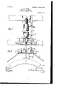
- Fig. 7 is a plan view of the automatic apron-guide.
- Fig. 8 is a side elevation of the automatic guide partly broken away.
- 1 indicates a steam-chamber having a smooth periphery, around which the material to be ironed is carried by an endless band or apron 2.
- the steam-chamber is in the form of a rotating cylinder, being driven by a worm-gear 3 and worm I, the
- the apron 2 passes about the steamchamber inthe direction of the arrow and then successively about the rolls 7, 8, 9, 10, 11, and 12, the rolls 7 and 12 being close together, thereby effecting a maximum amount of contact between the steam-chamber and the apron.
- the material to be ironed is for convenience first placed in a feed-box which, as shown, consists of a stationary back board 13 and a hinged front board 1 1, having pins or bolts 15, which cooperate with a series of holes 16 in the frame A to hold the front board in different positions to suit the requirements of different operators or for different classes of goods.
- the material is fed to the machine over a feed-board 17, at the rear of which is a feed-roll 18, situated above and arranged to draw the goods over the upper surface 19 of a steam chest 22, which is mounted on brackets 22*, secured to the frame of the machine, as shown in Figs. 2 and 3.
- the feed-roll 18 is mounted on arms 20, pivoted at 21, thus producing a uniform pressure of the roll upon the surface 19.
- the freedom of the roll to swing away from said surface protects the operators hands in case they should accidentally come under the roll.
- the roll 18 is driven by suitable gearing at a pcripheral speed slightly less than the speed of the main apron 2, thus producing a slight tension upon the goods between the feed-roll and the point where the goods enter between the apron and the steam-chamber.
- the roll 12 is driven by the apron, and the roll 18 is driven by gears from the roll 12.
- roll 12 is mounted in apair 01 links 23, pivoted at 24 to the main frame, the links inclining to the rear, whereby the roll is drawn naturally toward the steam-chamber by the tension of the apron 2.
- the goods are carried by the apron completely around the steam-chamber to the roll 7.
- they are stripped from the steamchamber by a dofiing-blade 25, carried around the roll 7 between the apron 2 and a series of tapes 26, said tapes passing through openings 27 in the dofling-blade, by which the tapes are guided.
- the dotFer-blade is mounted upon the upper side of a bar 28, which is pivoted at 29 near its lower side, thus permitting the blade to lie by gravity against the surface of the steam-chamber.
- a stop 30 is provided to prevent the tapes 26 from drawing the blade against the apron 2 should the tension of the bands 26 be sufiicient to do so.
- the hands after passing around the roll 7 pass around a padded roll 31, which is mounted upon weighted arms 32, which cause it to bear with some force upon the roll 7 and apron 2, thus insuring the driving of the bands 26, which pass between the roll 31 and the apron.
- To aflord easy access to the dofl'er-blade 25 I arrange the rolls?
- the arms 32 which carry the roll 31,. are provided with pivot-pins 41, which pass through slots 42 in brackets on the main frame. These slots permit the arms 32 to be thrown forward, so as to drop the roll 31 down onto or toward the roll 18 without stretching the bands 26, and it may be dropped still lower if the roll 18 be first removed.
- the roll 7 is mounted on pivoted arms 43, so that it may be drawn away from the blade 25 after the roll 31 is dropped. By means of the adjustment described the rolls 7, 18, and 31 may be displaced so as to expose either the steamchamber 22 or the dofier-blade, and thus these parts may be readily reached for adjustment or repairs.
- the goods operated on is thus stripped from the steam-chamber and made to follow the apron 2, being delivered on top of the return portion of the apron atits point of contact with the roll 31.
- the goods then ride to the rear on the apron over the roll 8 and are delivered upon a folding-table 33, provided a single machine is used, as illustrated in Fig. 1.
- I provide means for taking up any slack in the apron and for adjusting it properly to the rolls and the steam-chamber and also means for automatically producing a constant tension in the apron.
- I mount the roll 11 in sliding blocks 34, which are connected to adjusting-screws 35, provided with suitable cranks 36. By manipulating the screws 35 the apron may be properly adjusted to all of the rolls.
- I provide for a uniform tension on the apron by mounting the roll 10, as shown, in a pair down in unison.
- the roll 8 is mounted at one end in a swiveled bearing 44 and at the other end in a bearing-block 45, adapted to slide in a channel or way 46.
- the bearings 44 and 45 are arms 47 48, which support the sliding rod 49.
- apron On this red are adjustably mounted pads or plates 50, between which the apron travels, the pads being adjusted so that the apron will contact with one or the other should it travel laterally on the roll 8 from its normal position.
- a crank-pin 51 On the end of the spindle of the roll 8 adjacent to the sliding block 45 is a crank-pin 51, and which engages a slot in a sliding bar 52, having at its ends integral pawls 53 54, adapted to cooperate with the ratchets 56, formed in a stationary flange or bracket 57.
- the bar 52 is free to rock slightly on the pin 51; but it is confined on said pin by a head in such manner that but one of the pawls 53 54 can engage at a time with its corresponding ratchet.
- the bar 49 is pivotally connected with the pawl-bar 52, and the pawl-bar is thus controlled by the bar 49. It will be evident that a lateral movement of the apron one way or the other will efi'ect the engagement of the corresponding pawl 53 or 54 with its ratchet.
- the pawls are constantly reciprocated by the crank-pin, and when one or the other is engaged with its ratchet the bearingblock 45 is fed along and the roll 8 given a corresponding angular adjustment. This angular adjustment tends to restore the apron to central position, and should it go beyond central position a reverse movement of the parts will be effected by the other ratchet and pawl. In operation these devices keep the apron closely in central position, returning it automatically if it deviates one way or the other.
- the two series of ratchet-teeth 55 56 are inclined to a line parallel with the bearing-guide 46 for the purpose of arresting the travel of the bearing 45 when the lateral movement of the apron stops. It will be evident that if the series of ratchet-teeth were parallel with the guide 46 a given lateral movement of the apron would throw one of the pawls into engagement with its ratchet and might keep it in engagement with the ratchet sutficiently long to displace the roll 8 more than is necessary to bring the apron back to normal position.
- the pawls 53 and 54 keep moving away from the plane of the ratchetteeththat is, in a plane parallel with guide 46as they move successively from tooth to tooth and become automatically disengaged at or about the time the lateral movement of the apron stops.
- Fig. 2 I have shown a machine comprising two steam-chambers, with the necessary aprons for carrying the goods about them in succession, the aprons being arranged to carry the goods with one side against one of the steam-chambers and the opposite side against the other steam-chamber, thus ironing both sides of the goods.
- 1 and 1 indicate the two steam-chambers, and 2 and 2 the aprons cooperating with them.
- the steam-chamber 1 and its accessories are substantially the same as those shown in Fig. 1 and heretofore described, with the exception that the tension-adjusting device is omitted and the apron 2 is arranged to deliver the goods to the second steam-chamber instead of to the folding-table.
- the second steam-chamber may be of the same construction as the first.
- the arrangement of supporting-rolls for the apron of the second steam-chamber is substantially the reverse of the rolls for the first chamber, being as follows:
- the goods are delivered from the first steam-chamber between rolls 9 9 and between the aprons 2 2, which pass around these rolls, respectively.
- the two aprons then travel together around rolls 10 and 11 and partially around 12.
- the apron 2 separates from the apron 2 at the upper side of the roll 12 and returns to the steam-chamber 1 over a series of rolls 6O 61 and 11 and 12.
- the apron 2 after passing around roll 12 passes almost completely around the steam-chamber 1 to the roll 7 and thence to the roll 9 over the upper roll 8, which is preferably a guide-roll similar in construction and adjustment to the roll 8.
- the goods pass around the steamchamber 1, as heretofore described, and are delivered between rolls 9 9 instead of to the folding-table 33. They are then carried between the aprons 2 2 and delivered to the steam-chamber 1 at the roll 12. They pass thence around the steam-chamber 1 to the roll 7, at which point they are stripped from the steam-chamber by a doffer-blade 62, which delivers them to a folding-table 33, similar to the table 33.
- the tensionroll is brought to its proper position.
- the steam-chamber 1 when in the form of a rotating drum is driven by a worm 4. on the shaft 5.
- the roll 7* is mounted upon a pair of pivoted arms 63 in such manner that the apron 2 tends to draw it constantly against the steam-chamber.
- the roll is mounted upon a pair of arms 64 in such manner that the tension of the apron 2 holds it againstthe roll 12.
- the roll l2 is also mounted on pivoted arms 65 in such manner that the combined tension of the aprons 2 2 hold it against the steam-chamber.
Description
PATENTED FEB. 21, 1905.
'W. J. ASHER. IRONING MACHINE.
APPLICATION FILED MAY 12, 1903.
5 SHEETSBHEET l.
PATENTED FEB. 21, 1905.
W. J. ASHER. IRONING MACHINE.
APPLICATION FILED MAY 12, 1903.
5 SHEETS-SHEET 2 PATENTED FEB. 21, 1905.
W. J. ASHER. IRONING MACHINE.
APPLICATION nun MAY 12, 1902.
5 SHEETS-SHEET 3.
Q m \w wanna,
No. 782,813. PATBNTED FEB. 21, 1905. w. J. ASHER.
momma MACHINE.
APPLIUATION FILED MAY 12, 1903.
5 SHEETS-SHEET 5.
UNITED STATES Patented February 21, 1905.
WVILLIAM JAMES ASHER, OF WILLIMANTIC, CONNECTICUT.
lRONlNG-MACHINE.
SPECIFICATION forming part of Letters Patent No. 782,813, dated February 21, 1905.
Application filed May 12, 1903. Serial No. 156,816.
1'0 (Md w/wm it flea/y concern;
Be it known that I, WILLIAM J AMES ASHER, a citizen of the United States, residing at VVillimantic, in the county of Windham and State of Connecticut, have invented certain new and useful Improvements in Ironing-Machines, of which the following is a specification.
present invention comprises improvements in the class of laundry machinery used to smoothen or iron clothes, such machines being commonly termed ironing machines or mangles.
The invention may be embodied in asi-ngle machine adapted to iron one side of the goods or a double machine adapted to iron the goods first on one side and then on the other. Both forms will be described in the following specification. I use in a single machine a steamchamber which is preferably in the form of a cylindrical drum adapted to rotate on an axis, although in some instances 1 may use a stationary steam chamber having a smooth curved surface about which the goods arecarried by an endless apron. In the double machine the steam-chamber of the first machine is duplicated in the second, the machines being arranged in tandem and the aprons being arranged to carry the goods continuously, first about one steam-chamber and then about the other, delivering them upon a table upon which they may be folded or into a suitable receptacle. The parts of the double machine are coupled together and the aprons operated at the same speed.
My invention also includes improvements in the feeding mechanism for this class of machines and various adjustments which facilitate the operation of the machine and render its parts easy of access for renewal or repairs.
The machine is simple, practical, durable,
and economical and efiicient in operation.
I shall now describe the invention in detail, having reference to the accompanying drawings, in which- Figure 1 is a side elevation of a single machine illustrating the invention. Fig. 2 is a side elevation, partly in section, of a double machine illustrating the invention. Fig. 3 is an enlargement of part of Fig. 2. Fig. 418 a plan View of the parts shown in Fig. 3. Fig. 5 is a detail of the doffer-blade. Fig 6 is a detail of the device for automatically producing tension in the apron or aprons. Fig. 7 is a plan view of the automatic apron-guide. Fig. 8 is a side elevation of the automatic guide partly broken away.
Referring to Figs. 1, 3, and 4 of the drawing, 1 indicates a steam-chamber having a smooth periphery, around which the material to be ironed is carried by an endless band or apron 2. As illustrated, the steam-chamber is in the form of a rotating cylinder, being driven by a worm-gear 3 and worm I, the
latter being on a driving-shaft 5, driven bya pulley 6. The apron 2 passes about the steamchamber inthe direction of the arrow and then successively about the rolls 7, 8, 9, 10, 11, and 12, the rolls 7 and 12 being close together, thereby effecting a maximum amount of contact between the steam-chamber and the apron. The material to be ironed is for convenience first placed in a feed-box which, as shown, consists of a stationary back board 13 and a hinged front board 1 1, having pins or bolts 15, which cooperate with a series of holes 16 in the frame A to hold the front board in different positions to suit the requirements of different operators or for different classes of goods. The material is fed to the machine over a feed-board 17, at the rear of which is a feed-roll 18, situated above and arranged to draw the goods over the upper surface 19 of a steam chest 22, which is mounted on brackets 22*, secured to the frame of the machine, as shown in Figs. 2 and 3. The feed-roll 18 is mounted on arms 20, pivoted at 21, thus producing a uniform pressure of the roll upon the surface 19. The freedom of the roll to swing away from said surface protects the operators hands in case they should accidentally come under the roll. The roll 18 is driven by suitable gearing at a pcripheral speed slightly less than the speed of the main apron 2, thus producing a slight tension upon the goods between the feed-roll and the point where the goods enter between the apron and the steam-chamber. As shown, the roll 12 is driven by the apron, and the roll 18 is driven by gears from the roll 12. The
roll 12 is mounted in apair 01 links 23, pivoted at 24 to the main frame, the links inclining to the rear, whereby the roll is drawn naturally toward the steam-chamber by the tension of the apron 2. From the roll 12 the goods are carried by the apron completely around the steam-chamber to the roll 7. At this point. they are stripped from the steamchamber by a dofiing-blade 25, carried around the roll 7 between the apron 2 and a series of tapes 26, said tapes passing through openings 27 in the dofling-blade, by which the tapes are guided. The dotFer-blade is mounted upon the upper side of a bar 28, which is pivoted at 29 near its lower side, thus permitting the blade to lie by gravity against the surface of the steam-chamber. A stop 30 is provided to prevent the tapes 26 from drawing the blade against the apron 2 should the tension of the bands 26 be sufiicient to do so. The hands after passing around the roll 7 pass around a padded roll 31, which is mounted upon weighted arms 32, which cause it to bear with some force upon the roll 7 and apron 2, thus insuring the driving of the bands 26, which pass between the roll 31 and the apron. To aflord easy access to the dofl'er-blade 25, I arrange the rolls? and 31 so that they can be thrown back to expose the blade. As shown, the arms 32, which carry the roll 31,. are provided with pivot-pins 41, which pass through slots 42 in brackets on the main frame. These slots permit the arms 32 to be thrown forward, so as to drop the roll 31 down onto or toward the roll 18 without stretching the bands 26, and it may be dropped still lower if the roll 18 be first removed. The roll 7 is mounted on pivoted arms 43, so that it may be drawn away from the blade 25 after the roll 31 is dropped. By means of the adjustment described the rolls 7, 18, and 31 may be displaced so as to expose either the steamchamber 22 or the dofier-blade, and thus these parts may be readily reached for adjustment or repairs. The goods operated on is thus stripped from the steam-chamber and made to follow the apron 2, being delivered on top of the return portion of the apron atits point of contact with the roll 31. The goods then ride to the rear on the apron over the roll 8 and are delivered upon a folding-table 33, provided a single machine is used, as illustrated in Fig. 1.
I provide means for taking up any slack in the apron and for adjusting it properly to the rolls and the steam-chamber and also means for automatically producing a constant tension in the apron. For the former purpose I mount the roll 11 in sliding blocks 34, which are connected to adjusting-screws 35, provided with suitable cranks 36. By manipulating the screws 35 the apron may be properly adjusted to all of the rolls.
I provide for a uniform tension on the apron by mounting the roll 10, as shown, in a pair down in unison.
of weighted arms 37, which are fixed to a rockshat't 38, thus insuring that they move up and I prefer to mount the roll 10 in bushings 39.
In order to keep the apron 2 properly centered on the steam-chamber and its supporting-rolls, I provide an automatic angular adjustment of the roll 8, which is governed by the position of the apron itself, such angular adjustment being designed to return the apron to central position should it travel to one side or the other. The adjusting means are illustrated in Figs. 7 and 8. Referring to these figures, the roll 8 is mounted at one end in a swiveled bearing 44 and at the other end in a bearing-block 45, adapted to slide in a channel or way 46. On the bearings 44 and 45 are arms 47 48, which support the sliding rod 49. On this red are adjustably mounted pads or plates 50, between which the apron travels, the pads being adjusted so that the apron will contact with one or the other should it travel laterally on the roll 8 from its normal position. On the end of the spindle of the roll 8 adjacent to the sliding block 45 is a crank-pin 51, and which engages a slot in a sliding bar 52, having at its ends integral pawls 53 54, adapted to cooperate with the ratchets 56, formed in a stationary flange or bracket 57. The bar 52 is free to rock slightly on the pin 51; but it is confined on said pin by a head in such manner that but one of the pawls 53 54 can engage at a time with its corresponding ratchet. The bar 49 is pivotally connected with the pawl-bar 52, and the pawl-bar is thus controlled by the bar 49. It will be evident that a lateral movement of the apron one way or the other will efi'ect the engagement of the corresponding pawl 53 or 54 with its ratchet. The pawls are constantly reciprocated by the crank-pin, and when one or the other is engaged with its ratchet the bearingblock 45 is fed along and the roll 8 given a corresponding angular adjustment. This angular adjustment tends to restore the apron to central position, and should it go beyond central position a reverse movement of the parts will be effected by the other ratchet and pawl. In operation these devices keep the apron closely in central position, returning it automatically if it deviates one way or the other.
The two series of ratchet-teeth 55 56 are inclined to a line parallel with the bearing-guide 46 for the purpose of arresting the travel of the bearing 45 when the lateral movement of the apron stops. It will be evident that if the series of ratchet-teeth were parallel with the guide 46 a given lateral movement of the apron would throw one of the pawls into engagement with its ratchet and might keep it in engagement with the ratchet sutficiently long to displace the roll 8 more than is necessary to bring the apron back to normal position. By inclining the planes of the ratchetteeth, as shown, the pawls 53 and 54: keep moving away from the plane of the ratchetteeththat is, in a plane parallel with guide 46as they move successively from tooth to tooth and become automatically disengaged at or about the time the lateral movement of the apron stops.
In Fig. 2 I have shown a machine comprising two steam-chambers, with the necessary aprons for carrying the goods about them in succession, the aprons being arranged to carry the goods with one side against one of the steam-chambers and the opposite side against the other steam-chamber, thus ironing both sides of the goods. Referring to this figure, 1 and 1 indicate the two steam-chambers, and 2 and 2 the aprons cooperating with them. The steam-chamber 1 and its accessories are substantially the same as those shown in Fig. 1 and heretofore described, with the exception that the tension-adjusting device is omitted and the apron 2 is arranged to deliver the goods to the second steam-chamber instead of to the folding-table. The second steam-chamber may be of the same construction as the first. The arrangement of supporting-rolls for the apron of the second steam-chamber is substantially the reverse of the rolls for the first chamber, being as follows: The goods are delivered from the first steam-chamber between rolls 9 9 and between the aprons 2 2, which pass around these rolls, respectively. The two aprons then travel together around rolls 10 and 11 and partially around 12. The apron 2 separates from the apron 2 at the upper side of the roll 12 and returns to the steam-chamber 1 over a series of rolls 6O 61 and 11 and 12. The apron 2 after passing around roll 12 passes almost completely around the steam-chamber 1 to the roll 7 and thence to the roll 9 over the upper roll 8, which is preferably a guide-roll similar in construction and adjustment to the roll 8. The goods pass around the steamchamber 1, as heretofore described, and are delivered between rolls 9 9 instead of to the folding-table 33. They are then carried between the aprons 2 2 and delivered to the steam-chamber 1 at the roll 12. They pass thence around the steam-chamber 1 to the roll 7, at which point they are stripped from the steam-chamber by a doffer-blade 62, which delivers them to a folding-table 33, similar to the table 33. I apply tension to both bands 2 2 by mounting the rolllO on weighted arms 37 exactly as the roll 10 is shown mounted in the arms 37 The roll 11* is mounted in adjustable bearings 34, adapted to be adjusted to tighten the aprons by means of a screw 35 and crank 36*, the construction being similar to that previously described for adjusting the apron 2. The apron 2 is provided with a similar adjustment, as shown in Figs. 1 and 2. By adjusting the bearing-blocks 34, there being one on each side of the machine, the apron 2 may be adjusted to run accurately with the apron 2*, so that the tension produced by the roll 1O will be the samein both aprons. If it is desired to tighten or loosen both aprons simultaneously, this may be done by means of the adjustable bearing-blocks 34, there being one of said blocks on each side of the machine. By adjusting the bearing-blocks 34 the tensionroll is brought to its proper position. The steam-chamber 1 when in the form of a rotating drum is driven by a worm 4. on the shaft 5. The roll 7* is mounted upon a pair of pivoted arms 63 in such manner that the apron 2 tends to draw it constantly against the steam-chamber. Likewise the roll is mounted upon a pair of arms 64 in such manner that the tension of the apron 2 holds it againstthe roll 12. The roll l2 is also mounted on pivoted arms 65 in such manner that the combined tension of the aprons 2 2 hold it against the steam-chamber.
. Having thus described the invention, what I claim, and desire to secure by Letters Patent, is
1. In a machine of the class described, the combination of two steam-chambers arranged in tandem, two aprons and suitable guide-rolls therefor, said aprons being arranged and operated to carry the goods from the front of the primary steam-chamber around the same and back to the front thereof, then to deliver the goods between the said aprons at a point intermediate the steam-chambers, then to convey the goods to the rear of the secondary steam-chamber and thence around and in contact with said chamber to a point in the rear thereof.
2. In a machine of the class described, the combination of two steam-chambers arranged in tandem, two aprons and suitable guide-rolls therefor, said aprons being arranged and operated to carry the goods from the front of the primary steam-chamber around the same and back to the front thereof, then to deliver the goods between the said aprons at a point intermediate the steam-chambers, then to convey the goods to the rear of the secondary steam-chamber and thence around and in contact with said chamber to a point in the rear thereof, the said aprons and guide-rolls being so arranged that one side of the goods travels in contact with the primary steam-chamber and the other side in contact with the secondary steam-chamber, whereby the goods are ironed on both sides.
3. In a machine of the class described, the combination with a rotatable steam-drum, and an apron arranged to run in contact with said steam-drum, of a feed-roll arranged to run slightly slower than the apron, and a steamchamber upon which said feed-roll rests yieldingly, for the purpose described.
4:. In a machine of the class described, the combination with the rotating steam-drum, an endless apron arranged to run in contact with said steam-drum and a series of guide-rolls for the apron, of a pair of pivoted arms carrying one of said guide-rolls, said arms and roll being so arranged that the tension of the apron causes the roll to constantly bear upon the steam-drum, for the purpose set forth.
5. In a machine of the class described, the combination with a steam-chamber and an end less apron passing about said steam-chamber in one direction in contact therewith and in the opposite direction out of contact therewith, of guide-rolls about which the apron passes, a dotfer-blade having a series of openings and cooperating with the steam-chamber adjacent to one of said guide-rolls and a series of bands arranged to run through the openings in said dofi'er-blade and to cooperate with the apron, whereby the goods are stripped from the steam-chamber and delivered upon the return portion of the apron.
6. In a machine of the class described, the combination with the steam-chamber, and the endless apron, of the roll 7 about which the apron passes, thedofi'er-blade having openings therein, a series of bands passing through said openings and cooperating with the doiferblade to remove the goods from the steamchamber, the roll 31 about which said bands pass and the weighted pivotally-mounted arms carrying said roll, for the purpose set forth.
7. In a machine of the class described, the combination with the steam-chamber, and the endless apron, of the roll 7 about which the apron passes, the pivotally-mounted arms in which said roll is journaled, the dofl'er-blade, the tapes cooperating with said blade, the roll 31 and the pivotally-mounted arms in which said roll 31 is journaled, for the purpose set forth.
8. In a machine of the class described, the combination of two rotatable cylindrical steam chambers, means for rotating said chambers, two endless aprons and guide-rolls for causing said aprons to travel in contact with said steam-chambers respectively, the said aprons being driven by their respective steam chambers, said steam chambers and aprons being arranged to iron the goods first on one side and then on the other.
9. In a machine of the class described, the combination of two rotatable, cylindrical steam chambers, means for rotating said chambers, two endless aprons and guide-rolls for causing said aprons to travel in contact with said steam-chambers respectively, said steam-chambers being rotated in opposite directions and the said aprons being driven by their respective steam-chambers.
10. In a machine of the class described, the combination with two rotatable steam-chambers and two endless aprons arranged to co operate with said chambers to carry the goods first about one of said chambers and then about the other, of means for adjusting said aprons relatively to the same tension, and a weighted tension-roll operating on both aprons to maintain a common tension therein.
11. In a machine of the class described, the combination of two rotatable steam-drums arranged in tandem, two aprons and suitable guide-rolls therefor, said aprons being arranged and operated to carry the goods from the front of the primary steam-drum around the same and back to the front thereof, then to deliver the goods between the said aprons at a point intermediate the steam-drums, then to convey the goods to the rear of the secondary steam-drum, and thence around and in contact with said drum to a point in the rear thereof.
12. In a machine of the class described, the combination of two rotatable steam-drums arranged in tandem, two aprons and suitable guide-rolls therefor, said aprons being arranged and operated to carry the goods from the front of the primary steam-drum around the same and back to the front thereof, then to deliver the goods between the said aprons at a point intermediate the said steam-drums, then to convey the goods to the rear of the secondary steam-drum, and thence around and in contact with said drum to a point in the rear thereof, the said aprons and guide-rolls being so arranged that one side of the goods travels in contact with the primary steamdrum and the other side in contact with the secondary steam-drum,whereby the goods are ironed on both sides.
In testimony whereof I have signed my name to this specification in the presence of two subscribing witnesses.
WILLIAM J AMES ASHER.
Witnesses:
O. R. HIBBERD, SAMUEL J. MILLER.
Priority Applications (2)
| Application Number | Priority Date | Filing Date | Title |
|---|---|---|---|
| US15681603A US782813A (en) | 1903-05-12 | 1903-05-12 | Ironing-machine. |
| US286419A US813995A (en) | 1903-05-12 | 1905-11-08 | Automatic apron or belt guide. |
Applications Claiming Priority (1)
| Application Number | Priority Date | Filing Date | Title |
|---|---|---|---|
| US15681603A US782813A (en) | 1903-05-12 | 1903-05-12 | Ironing-machine. |
Publications (1)
| Publication Number | Publication Date |
|---|---|
| US782813A true US782813A (en) | 1905-02-21 |
Family
ID=2851299
Family Applications (1)
| Application Number | Title | Priority Date | Filing Date |
|---|---|---|---|
| US15681603A Expired - Lifetime US782813A (en) | 1903-05-12 | 1903-05-12 | Ironing-machine. |
Country Status (1)
| Country | Link |
|---|---|
| US (1) | US782813A (en) |
-
1903
- 1903-05-12 US US15681603A patent/US782813A/en not_active Expired - Lifetime
Similar Documents
| Publication | Publication Date | Title |
|---|---|---|
| US3198516A (en) | Laundry flatwork feeder | |
| US782813A (en) | Ironing-machine. | |
| US440292A (en) | wiles | |
| US1186504A (en) | Fabric-trimming machine. | |
| US413260A (en) | Island | |
| US1385746A (en) | Cloth-guiding device for cloth-finishing machines | |
| US308081A (en) | lodge | |
| US1139513A (en) | Cloth-winding machine. | |
| US416343A (en) | Machine for tentering | |
| US568508A (en) | Island | |
| US478236A (en) | Machine for waxing velvets | |
| US1232653A (en) | Dye-beck. | |
| US1064644A (en) | Automatic edge-ironer for collars and cuffs. | |
| US1304630A (en) | Web-feeding mechanism for printing-machines | |
| US156947A (en) | Improvement in machines for rubbing oil-cloth | |
| US1550380A (en) | Machine for cutting pile fabrics | |
| US793000A (en) | Ball-winding machine. | |
| US762415A (en) | Hide-working machine. | |
| US790360A (en) | Mangle. | |
| US762605A (en) | Mangle. | |
| US139201A (en) | Improvement in machines for pressing clothes | |
| US534649A (en) | Cloth-stretching machine | |
| US745353A (en) | Hide-working machine. | |
| US417199A (en) | paine | |
| US570866A (en) | Burnish ing-machine |