US7826749B2 - Method and system for quantum key distribution over multi-user WDM network with wavelength routing - Google Patents
Method and system for quantum key distribution over multi-user WDM network with wavelength routing Download PDFInfo
- Publication number
- US7826749B2 US7826749B2 US11/231,042 US23104205A US7826749B2 US 7826749 B2 US7826749 B2 US 7826749B2 US 23104205 A US23104205 A US 23104205A US 7826749 B2 US7826749 B2 US 7826749B2
- Authority
- US
- United States
- Prior art keywords
- wavelength
- transmitter
- receivers
- receiver
- light
- Prior art date
- Legal status (The legal status is an assumption and is not a legal conclusion. Google has not performed a legal analysis and makes no representation as to the accuracy of the status listed.)
- Active, expires
Links
Images


Classifications
-
- H—ELECTRICITY
- H04—ELECTRIC COMMUNICATION TECHNIQUE
- H04J—MULTIPLEX COMMUNICATION
- H04J14/00—Optical multiplex systems
- H04J14/02—Wavelength-division multiplex systems
- H04J14/0227—Operation, administration, maintenance or provisioning [OAMP] of WDM networks, e.g. media access, routing or wavelength allocation
- H04J14/0241—Wavelength allocation for communications one-to-one, e.g. unicasting wavelengths
- H04J14/0242—Wavelength allocation for communications one-to-one, e.g. unicasting wavelengths in WDM-PON
- H04J14/0245—Wavelength allocation for communications one-to-one, e.g. unicasting wavelengths in WDM-PON for downstream transmission, e.g. optical line terminal [OLT] to ONU
- H04J14/0246—Wavelength allocation for communications one-to-one, e.g. unicasting wavelengths in WDM-PON for downstream transmission, e.g. optical line terminal [OLT] to ONU using one wavelength per ONU
-
- H—ELECTRICITY
- H04—ELECTRIC COMMUNICATION TECHNIQUE
- H04B—TRANSMISSION
- H04B10/00—Transmission systems employing electromagnetic waves other than radio-waves, e.g. infrared, visible or ultraviolet light, or employing corpuscular radiation, e.g. quantum communication
- H04B10/50—Transmitters
- H04B10/501—Structural aspects
- H04B10/503—Laser transmitters
-
- H—ELECTRICITY
- H04—ELECTRIC COMMUNICATION TECHNIQUE
- H04B—TRANSMISSION
- H04B10/00—Transmission systems employing electromagnetic waves other than radio-waves, e.g. infrared, visible or ultraviolet light, or employing corpuscular radiation, e.g. quantum communication
- H04B10/50—Transmitters
- H04B10/516—Details of coding or modulation
- H04B10/548—Phase or frequency modulation
-
- H—ELECTRICITY
- H04—ELECTRIC COMMUNICATION TECHNIQUE
- H04B—TRANSMISSION
- H04B10/00—Transmission systems employing electromagnetic waves other than radio-waves, e.g. infrared, visible or ultraviolet light, or employing corpuscular radiation, e.g. quantum communication
- H04B10/70—Photonic quantum communication
-
- H—ELECTRICITY
- H04—ELECTRIC COMMUNICATION TECHNIQUE
- H04J—MULTIPLEX COMMUNICATION
- H04J14/00—Optical multiplex systems
- H04J14/02—Wavelength-division multiplex systems
- H04J14/0278—WDM optical network architectures
- H04J14/0282—WDM tree architectures
-
- H—ELECTRICITY
- H04—ELECTRIC COMMUNICATION TECHNIQUE
- H04J—MULTIPLEX COMMUNICATION
- H04J14/00—Optical multiplex systems
- H04J14/02—Wavelength-division multiplex systems
- H04J14/03—WDM arrangements
- H04J14/0307—Multiplexers; Demultiplexers
-
- H—ELECTRICITY
- H04—ELECTRIC COMMUNICATION TECHNIQUE
- H04L—TRANSMISSION OF DIGITAL INFORMATION, e.g. TELEGRAPHIC COMMUNICATION
- H04L9/00—Cryptographic mechanisms or cryptographic arrangements for secret or secure communications; Network security protocols
- H04L9/08—Key distribution or management, e.g. generation, sharing or updating, of cryptographic keys or passwords
- H04L9/0816—Key establishment, i.e. cryptographic processes or cryptographic protocols whereby a shared secret becomes available to two or more parties, for subsequent use
- H04L9/0852—Quantum cryptography
-
- G—PHYSICS
- G02—OPTICS
- G02B—OPTICAL ELEMENTS, SYSTEMS OR APPARATUS
- G02B6/00—Light guides; Structural details of arrangements comprising light guides and other optical elements, e.g. couplings
- G02B6/10—Light guides; Structural details of arrangements comprising light guides and other optical elements, e.g. couplings of the optical waveguide type
- G02B6/12—Light guides; Structural details of arrangements comprising light guides and other optical elements, e.g. couplings of the optical waveguide type of the integrated circuit kind
- G02B6/12007—Light guides; Structural details of arrangements comprising light guides and other optical elements, e.g. couplings of the optical waveguide type of the integrated circuit kind forming wavelength selective elements, e.g. multiplexer, demultiplexer
- G02B6/12009—Light guides; Structural details of arrangements comprising light guides and other optical elements, e.g. couplings of the optical waveguide type of the integrated circuit kind forming wavelength selective elements, e.g. multiplexer, demultiplexer comprising arrayed waveguide grating [AWG] devices, i.e. with a phased array of waveguides
-
- G—PHYSICS
- G02—OPTICS
- G02B—OPTICAL ELEMENTS, SYSTEMS OR APPARATUS
- G02B6/00—Light guides; Structural details of arrangements comprising light guides and other optical elements, e.g. couplings
- G02B6/24—Coupling light guides
- G02B6/26—Optical coupling means
- G02B6/28—Optical coupling means having data bus means, i.e. plural waveguides interconnected and providing an inherently bidirectional system by mixing and splitting signals
- G02B6/293—Optical coupling means having data bus means, i.e. plural waveguides interconnected and providing an inherently bidirectional system by mixing and splitting signals with wavelength selective means
- G02B6/29346—Optical coupling means having data bus means, i.e. plural waveguides interconnected and providing an inherently bidirectional system by mixing and splitting signals with wavelength selective means operating by wave or beam interference
- G02B6/2935—Mach-Zehnder configuration, i.e. comprising separate splitting and combining means
-
- H—ELECTRICITY
- H04—ELECTRIC COMMUNICATION TECHNIQUE
- H04J—MULTIPLEX COMMUNICATION
- H04J14/00—Optical multiplex systems
- H04J14/02—Wavelength-division multiplex systems
- H04J14/0227—Operation, administration, maintenance or provisioning [OAMP] of WDM networks, e.g. media access, routing or wavelength allocation
Definitions
- the present invention relates to a system for communicating encrypted data.
- the present invention relates to the technique known as quantum key distribution over multi-user wavelength division multiplexing (WDM) network with wavelength routing.
- WDM wavelength division multiplexing
- Quantum cryptography is believed to be a natural candidate to enhance conventional cryptographies because it can provide ultimate security by the laws of quantum theory. Most of research in this field is centered on point-to-point transmission between two users. At present, quantum cryptography has been successfully achieved in a point-to-point link in optical fiber and free space. However, there are limited achievements on quantum key distribution over network to date. There exist more problems for quantum key distribution over network than that over point-to-point transmission. In fact, it has been thought that it is a difficult problem to distribute quantum keys over network.
- FIG. 1 shows a conventional configuration of quantum key distribution over a star network, which exploits four phase shifts of weak pulse strings based on BB84 protocol at transmitter and receiver.
- a transmitter (Tx) and receivers (Rx 1 -Rx 3 ) use a phase modulator to encode and decode the phase shifts, and the transmitter launches a 3-photon pulse with a phase shift randomly chosen from four phases, (e.g. 0, ⁇ /2, ⁇ and 3 ⁇ /2) into the fiber.
- the pulse is then equally split among the 3 receivers. For measurement, each receiver needs synchronization with the sent pulse.
- the setup cannot identify which user should receive the signal because all users in the depicted network can simultaneously receive signals from the sender even if she or he is not the intended receiver. That is to say, this system cannot establish a link just between two specific users to implement quantum key distribution.
- the present invention provides a communication system for quantum key distribution, in which a transmitter can communicate over a conventional optical communications network with a plurality of receivers by using a different secret key sent at a different wavelength for each different receiver.
- the present invention also provides a communication system for quantum key distribution with a relatively simple structure and high communication efficiency.
- the present invention provides a method of quantum key distribution between a transmitter and a plurality of receivers over a multi-user wavelength division multiplexing (WDM) network with wavelength routing which comprises: 1) assigning a different receiving-wavelength to each of the receivers, respectively; 2) selecting a receiver among the receivers to be communicated with the transmitter; and 3) transmitting quantum key signals from the transmitter to the selected receiver over the WDM network, wherein the quantum key signals are at a wavelength identical to the receiving-wavelength of the receiver.
- WDM wavelength division multiplexing
- the present invention further provides a communication system for quantum key distribution comprising a transmitter; a plurality of receivers, each having a distinct receiving-wavelength; and a multi-user WDM network linking the transmitter to the receivers, wherein the transmitter selects a receiver among the receivers to be communicated therewith and transmits quantum signals to the selected receiver over the WDM network.
- the quantum signals transmitted are at a wavelength equal to the receiving-wavelength of the receiver.
- a wavelength routing technology is employed to implement quantum key distribution for a plurality of receivers.
- the wavelength routing can be realized by a wavelength division demultiplexer, which may be in the form of an array waveguide grating (AWG).
- AWG array waveguide grating
- the system can use all-fiber connections, which is suitable for optical fiber network.
- continuous wave light is employed in the system, which can improve the security of the system.
- differential phase detection is also employed in the present invention, in order to overcome the influence of a temperature shift and phase shift in the system, which can further make the system simple and stable.
- the present invention employs a randomly phase-modulated light of weak coherent states, e.g. two non-orthogonal states with phase shifts 0 and ⁇ , which can improve the communication efficiency of the system.
- FIG. 1 is a schematic view showing the principle of quantum key distribution over star network in the prior art
- FIG. 2 is a schematic view showing principles of a wavelength routing technology employed in a communication system for quantum key distribution over a multi-user WDM network according to the present invention
- FIG. 3 is a schematic view of a communication system according to the present invention, which illustrates a structure of a channel between a transmitter and a receiver;
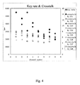
- FIG. 4 shows an experimental result of the key rate and crosstalk of the communication between the transmitter and 8 different receivers over an 8-user WDM network according to the invention.
- FIG. 2 shows an embodiment of the communication system for quantum key distribution over a multi-user WDM network according to the present invention.
- Wavelength routing technology is used to implement quantum key distribution among specific users in the invention.
- the wavelength routing can be realized by a wavelength division demultiplexer 400 , such as an array waveguide grating (AWG). Therefore, the transmitter 100 can choose a wavelength to establish a channel (e.g. from channel 1 to channel n) with each receiver so that the transmitter 100 does not need to send signals to all the receivers. For example, if a receiver 210 having a receiving-wavelength, ⁇ 1 , is selected to communicate with the transmitter 100 , the transmitter will transmit quantum signals with a wavelength equal to ⁇ 1 . The signals, after passing through an optical fiber 300 , reach the array waveguide grating 400 , which can route the quantum signals to the receiver 210 only.
- AMG array waveguide grating
- the transmitter 100 can communicate the quantum signals with only one selected receiver.
- tuning the transmitter wavelength or selecting an appropriate wavelength of a multi-wavelength transmitter one single transmitter can transmit quantum signals to each of the receivers 200 by using WDM technology.
- Receiving-wavelengths that can be assigned to each of the receivers in this embodiment are listed in Table 1.
- FIG. 3 a configuration for transmitting quantum signals between a transmitter and an intended (selected) receiver over a multi-user WDM network according to the present invention is described.
- a tunable laser 101 at the transmitter 100 emits a continuous wave (CW) light whose wavelength corresponds to the receiving-wavelength of the receiver 210 , into a phase modulator 102 .
- a random phase shift of 0 or ⁇ generated by a random data signal generator 104 is added to the CW light.
- the CW light with a random phase shift is attenuated to single photons, with an average photon number less than one within a measured gate period, at the exit of a variable optical attenuator 103 , which is coupled into a 8.5 km standard single mode optical fiber 300 .
- the attenuated light signal is sent to the AWG 400 , to determine which user is selected via wavelength routing.
- the AWG 400 provides a plurality of output ports 401 - 40 n , each having a distinct central wavelength and a bandwidth that corresponds to the receiving-wavelength of each of the receivers. And then, through the AWG 400 , the attenuated signals arrive at the selected receiver 210 corresponding to the receiving-wavelength.
- the receiver 210 provides an asymmetric Mach-Zehnder interferometer 218 to reconstruct a phase shift introduced by the transmitter 100 .
- the asymmetric Mach-Zehnder interferometer 218 comprises a first 50/50 beam splitter 211 , a long arm 212 , a short arm 213 , and a second 50/50 beam splitter 214 .
- the beam splitter 211 is employed for splitting the incoming signals into two portions respectively entering the long arm 212 and the short arm 213 .
- the two split light signals are recombined by the beam splitter 214 , in which the time difference between the two arms 212 and 213 is set equal to a time interval of a phase modulation period.
- the random data signal generator 104 of the transmitter 100 can synchronize the phase modulator 102 to modulate the light with the time interval of the phase modulation period equal to the time difference experienced by the light while traveling across the two arms.
- the Mach-Zehnder interferometer 218 an interference between the photons of the two arms occurs.
- the receiver 210 can detect single photons created by the constructively interfered signal by a single photon detector module 219 comprising two single photon detectors 215 and 216 respectively connected to two outputs of the beam splitter 214 .
- the detector module works in gated mode with 2.5 ns and 100 KHz.
- the data can be stored in a computer via data capture software.
- a time slot measurement device 217 can be provided in the single photon detector module 219 for measuring the time slots at which a photon is detected at the detectors.
- the receiver 210 tells the transmitter 100 the time slots measured. From this time message and the modulation state of the photons, the transmitter knows which detector clicked in the receiver. Under an agreement that the click by the detector 215 denotes “0” and the click by the detector 216 denotes “1”, for example, the transmitter 100 and the receiver 210 will obtain an identical quantum key.
- the transmitter 100 can choose a wavelength to establish a channel, channel 1, with the receiver 210 so that the transmitter 100 does not need to send the signal to the other receivers.
- the transmitter 100 can communicate with any of the single receivers in a similar way described above.
- the laser of the present invention is a narrow band laser source, so that the light emitted from the laser has a bandwidth narrower than the bandwidth of each of the output ports (from output port 401 to 40 n ) of the array waveguide grating.
- the laser 101 can be tuned from 1,475 nm to 1,600 nm.
- the receiving-wavelengths used in the embodiment are listed in Table 1.
- the single photon signals have been measured in each channel and crosstalks due to other channels are also detected.
- the count rate of the experiment is less than 1 ⁇ 10 4 counts/s, which corresponds to less than 0.1 count in a measured slot at the transmitter, in order to guarantee a single photon in the modulation time slot. After about 12 dB transmission loss, there are about 6% single photons to arrive at a receiver.
- the percentage of the used gates in the receivers 200 is shown in Table 1, and the count rates of single photons arriving at the receivers 200 from the transmitter 100 are also shown in Table 1.
- the error rte in each channel of the 8-user network is listed in Table 2.
- This system can use all-fiber connections, which is suitable to optical fiber networks.
- the quantum key signal of the system is carried by the phase difference between two sequential phases.
- An advantage to adopt differential phase detection is to overcome the influence of the temperature shift and phase shift in the system, which also makes the system simple.
- Another advantage is of high communication efficiency.
- at least two measurement bases are necessary when detection is done at receivers. In principle, there are only 50 percent of outcomes that are correct. Therefore, it will make a 3 dB loss, i.e. BB84 protocol has been used. However, one can use all of the measured outcomes in the present system.
- Continuous wave light is employed in the system of the invention, which can improve the security of the system.
- an eavesdropper, Eve cannot measure the period of the phase modulation. Therefore, Eve cannot know the detailed information of the interferometer. In fact, single pulses will lead to leaking more information (interferometer structure parameter, which is very important to form quantum keys) to eavesdropper. If continuous light is adopted, then eavesdropper cannot know the difference between the two arms of the interferometer, which further improves the security of this system.
- the construct according to the invention has lower noise because there is no return signals (which can cause interference) in the current structure. That is also another advantage.
- FIG. 4 shows that experimental key rates for the 8 channels vary from about 2 kb/s to more than 5 kb/s, which are shown in black diamond. Other dots in FIG. 4 show the crosstalks caused by the referred channels.
- the crosstalk due to channel 1 is the largest because of its highest single photon rate.
- there is an upper bound for the loss in the system which includes fiber transmission loss, component insertion loss, loss from wavelength routing and some loss caused by imperfect alignment.
- the total loss of about 12 dB is much less than the secure upper bound of 31 dB for the mean photon number per bit of 0.1.
- the crosstalk is mainly caused by the wavelength demultiplexing device, AWG, and laser source.
- quantum key distribution over multi-user network using wavelength routing is achieved experimentally, which overcomes the broadcasting problem of the tree network. Furthermore, a differential phase modulation is applied to continuous wave light, which can eliminate the variations caused by temperature and polarization fluctuations in the system. Moreover, the higher key generation efficiency with a simple configuration demonstrated in this disclosure is suitable to practical applications.
Landscapes
- Engineering & Computer Science (AREA)
- Computer Networks & Wireless Communication (AREA)
- Signal Processing (AREA)
- Physics & Mathematics (AREA)
- Electromagnetism (AREA)
- Optics & Photonics (AREA)
- Theoretical Computer Science (AREA)
- Computer Security & Cryptography (AREA)
- Optical Communication System (AREA)
- Data Exchanges In Wide-Area Networks (AREA)
Abstract
Description
| TABLE 1 | |||
| Receiving-Wavelength | Percentage of | Arrival Counts | |
| Receivers | FWHM(nm) | Used Gates | (s−1) |
| 1 | 1549.32 (0.018) | 8-9% | 558.305 |
| 2 | 1551.12 (0.016) | 7-8% | 477.7992 |
| 3 | 1552.4 (0.017) | 4-5% | 316.36 |
| 4 | 1554.145 (0.017) | 6-7% | 422.407 |
| 5 | 1555.689 (0.017) | 4-5% | 303.2212 |
| 6 | 1557.375 (0.017) | 3-4% | 245.2329 |
| 7 | 1558.996 (0.018) | 4-5% | 332.095 |
| 8 | 1560.615 (0.016) | 2-3% | 207.4174 |
| TABLE 2 | ||
| |
||
| 1 | 2 | 3 | 4 | 5 | 6 | 7 | 8 | ||
| Error Rates (%) | 1.93 | 2.15 | 2.75 | 3.19 | 2.76 | 2.73 | 2.24 | 6.26 |
Claims (20)
Priority Applications (7)
| Application Number | Priority Date | Filing Date | Title |
|---|---|---|---|
| US11/231,042 US7826749B2 (en) | 2005-09-19 | 2005-09-19 | Method and system for quantum key distribution over multi-user WDM network with wavelength routing |
| JP2008530301A JP2009509366A (en) | 2005-09-19 | 2006-07-24 | Quantum key distribution method and system on multi-user WDM network using wavelength routing |
| PCT/CN2006/001815 WO2007033560A1 (en) | 2005-09-19 | 2006-07-24 | Method and system for quantum key distribution over multi-user wdm network with wavelength routing |
| HK08108887.1A HK1117967B (en) | 2005-09-19 | 2006-07-24 | Methods and system for quantum key distribution over multi-user wdm network with wavelength routing |
| EP06761549.2A EP1927208B1 (en) | 2005-09-19 | 2006-07-24 | Method and system for quantum key distribution over multi-user wdm network with wavelength routing |
| CN2006800227733A CN101208890B (en) | 2005-09-19 | 2006-07-24 | Method and system for quantum key distribution over multi-user WDM network using wavelength routing |
| KR1020087006610A KR101031978B1 (en) | 2005-09-19 | 2006-07-24 | Quantum key distribution method and system through multi-user WDM network using wavelength routing |
Applications Claiming Priority (1)
| Application Number | Priority Date | Filing Date | Title |
|---|---|---|---|
| US11/231,042 US7826749B2 (en) | 2005-09-19 | 2005-09-19 | Method and system for quantum key distribution over multi-user WDM network with wavelength routing |
Publications (2)
| Publication Number | Publication Date |
|---|---|
| US20070065154A1 US20070065154A1 (en) | 2007-03-22 |
| US7826749B2 true US7826749B2 (en) | 2010-11-02 |
Family
ID=37884252
Family Applications (1)
| Application Number | Title | Priority Date | Filing Date |
|---|---|---|---|
| US11/231,042 Active 2028-09-01 US7826749B2 (en) | 2005-09-19 | 2005-09-19 | Method and system for quantum key distribution over multi-user WDM network with wavelength routing |
Country Status (6)
| Country | Link |
|---|---|
| US (1) | US7826749B2 (en) |
| EP (1) | EP1927208B1 (en) |
| JP (1) | JP2009509366A (en) |
| KR (1) | KR101031978B1 (en) |
| CN (1) | CN101208890B (en) |
| WO (1) | WO2007033560A1 (en) |
Cited By (4)
| Publication number | Priority date | Publication date | Assignee | Title |
|---|---|---|---|---|
| US20220173895A1 (en) * | 2019-03-22 | 2022-06-02 | British Telecommunications Public Limited Company | Improvements to qkd network architectures |
| US20230393335A1 (en) * | 2020-09-25 | 2023-12-07 | General Electric Company | Photonic integrated circuit design for plug-and-play measurement device independent-quantum key distribution (mdi-qkd) |
| US12250298B2 (en) | 2019-03-22 | 2025-03-11 | British Telecommunications Public Limited Company | To QKD network architectures |
| US12556379B2 (en) * | 2022-07-22 | 2026-02-17 | Kabushiki Kaisha Toshiba | QKD system, electronic apparatus, multiplexing apparatus, and computer program product |
Families Citing this family (87)
| Publication number | Priority date | Publication date | Assignee | Title |
|---|---|---|---|---|
| US7639947B2 (en) * | 2005-09-19 | 2009-12-29 | The Chinese University Of Hong Kong | System and methods for quantum key distribution over WDM links |
| GB2441790A (en) * | 2006-09-12 | 2008-03-19 | Qinetiq Ltd | Electro-optic waveguide polarisation modulator |
| US8855316B2 (en) * | 2008-01-25 | 2014-10-07 | Qinetiq Limited | Quantum cryptography apparatus |
| GB0801395D0 (en) * | 2008-01-25 | 2008-03-05 | Qinetiq Ltd | Network having quantum key distribution |
| GB0801408D0 (en) * | 2008-01-25 | 2008-03-05 | Qinetiq Ltd | Multi-community network with quantum key distribution |
| GB0801492D0 (en) | 2008-01-28 | 2008-03-05 | Qinetiq Ltd | Optical transmitters and receivers for quantum key distribution |
| GB0809045D0 (en) * | 2008-05-19 | 2008-06-25 | Qinetiq Ltd | Quantum key distribution involving moveable key device |
| GB0809044D0 (en) * | 2008-05-19 | 2008-06-25 | Qinetiq Ltd | Multiplexed QKD |
| GB0809038D0 (en) * | 2008-05-19 | 2008-06-25 | Qinetiq Ltd | Quantum key device |
| GB0819665D0 (en) * | 2008-10-27 | 2008-12-03 | Qinetiq Ltd | Quantum key dsitribution |
| GB0822253D0 (en) * | 2008-12-05 | 2009-01-14 | Qinetiq Ltd | Method of establishing a quantum key for use between network nodes |
| GB0822254D0 (en) * | 2008-12-05 | 2009-01-14 | Qinetiq Ltd | Method of performing authentication between network nodes |
| GB0822356D0 (en) * | 2008-12-08 | 2009-01-14 | Qinetiq Ltd | Non-linear optical device |
| US8483525B2 (en) | 2009-01-09 | 2013-07-09 | Nippon Telegraph And Telephone Corporation | Optical wavelength multiplexing/demultiplexing circuit, optical module using optical wavelength multiplexing/demultiplexing circuit, and communication system |
| GB0917060D0 (en) | 2009-09-29 | 2009-11-11 | Qinetiq Ltd | Methods and apparatus for use in quantum key distribution |
| GB201020424D0 (en) | 2010-12-02 | 2011-01-19 | Qinetiq Ltd | Quantum key distribution |
| GB2529101B (en) * | 2011-06-17 | 2016-03-23 | Toshiba Res Europ Ltd | A quantum communication system |
| ITBO20120713A1 (en) * | 2011-12-30 | 2013-07-01 | Selex Sistemi Integrati Spa | METHOD AND SYSTEM OF ESTIMATION OF THE NOISE OF AN ENTANGLED STATE WITH TWO PHOTOS |
| CN102624365A (en) * | 2012-02-24 | 2012-08-01 | 西南交通大学 | A high-speed binary true random code generator based on nonlinear photoelectric delay oscillator |
| WO2014060793A1 (en) | 2012-10-15 | 2014-04-24 | Nokia Corporation | Quantum key distribution |
| WO2014068959A1 (en) * | 2012-11-01 | 2014-05-08 | 日本電気株式会社 | Light-receiving device in optical communication system, photon-detector control method and device, and photon-detector dark-count-rate evaluation method |
| CN103824487B (en) * | 2014-02-27 | 2016-01-13 | 安徽问天量子科技股份有限公司 | Based on eavesdropping apparatus for demonstrating and the method thereof of quantum key communication |
| CN104092538B (en) * | 2014-07-15 | 2017-04-12 | 华南师范大学 | Multi-user wavelength division multiplexing QKD network system and secret key distributing and sharing method thereof |
| KR101610747B1 (en) * | 2014-08-19 | 2016-04-08 | 한국과학기술연구원 | Method and apparatus for quantum cryptographic communication |
| CN104486317B (en) * | 2014-12-08 | 2017-12-01 | 国家电网公司 | A kind of common fine transmission method of multi-user quantum encryption key distribution for power system |
| CN107204812B (en) * | 2016-03-18 | 2019-07-16 | 国科量子通信网络有限公司 | The method and device of quantum key distribution and passive optical access network fusion |
| CN107465502A (en) | 2016-06-02 | 2017-12-12 | 华为技术有限公司 | A kind of quantum communications method and relevant apparatus |
| CN106789030B (en) * | 2017-01-13 | 2019-10-22 | 华南师范大学 | A local active phase compensation system and method |
| CN106685655B (en) * | 2017-01-16 | 2019-08-16 | 华南师范大学 | A kind of phase polarization multiple degrees of freedom modulation QKD network system and method |
| JP6885467B2 (en) * | 2017-08-22 | 2021-06-16 | 日本電信電話株式会社 | Share generation device, share conversion device, secret calculation system, share generation method, share conversion method, program, and recording medium |
| CN109510701B (en) * | 2017-09-15 | 2021-10-01 | 华为技术有限公司 | Continuous variable quantum key distribution device and method |
| US11411720B2 (en) * | 2018-04-11 | 2022-08-09 | Nippon Telegraph And Telephone Corporation | Key distribution system, terminal device, key distribution method, and program |
| CN108540286B (en) * | 2018-06-11 | 2023-12-05 | 广东尤科泊得科技发展有限公司 | Switchable multi-type quantum terminal network communication system and key distribution method |
| KR20200022594A (en) | 2018-08-23 | 2020-03-04 | 인천대학교 산학협력단 | System and method for quantum key distribution based on single link |
| US11343084B2 (en) * | 2019-03-01 | 2022-05-24 | John A. Nix | Public key exchange with authenticated ECDHE and security against quantum computers |
| GB2582900A (en) | 2019-03-18 | 2020-10-14 | Pqshield Ltd | Cryptography using a cryptographic state |
| CN110175018B (en) * | 2019-03-28 | 2024-09-17 | 华中科技大学 | A multi-wavelength parallel photon random number generator |
| US11258601B1 (en) * | 2019-06-04 | 2022-02-22 | Trend Micro Incorporated | Systems and methods for distributed digital rights management with decentralized key management |
| JP7173328B2 (en) * | 2019-06-10 | 2022-11-16 | 日本電信電話株式会社 | Secure division system, secure computing device, secure division method, and program |
| CN110336720B (en) * | 2019-06-29 | 2021-08-20 | 华为技术有限公司 | Device control method and device |
| US11477016B1 (en) | 2019-09-10 | 2022-10-18 | Wells Fargo Bank, N.A. | Systems and methods for post-quantum cryptography optimization |
| US11626983B1 (en) | 2019-09-10 | 2023-04-11 | Wells Fargo Bank, N.A. | Systems and methods for post-quantum cryptography optimization |
| US11343270B1 (en) | 2019-09-10 | 2022-05-24 | Wells Fargo Bank, N.A. | Systems and methods for post-quantum cryptography optimization |
| US11240014B1 (en) | 2019-09-10 | 2022-02-01 | Wells Fargo Bank, N.A. | Systems and methods for post-quantum cryptography optimization |
| US11451383B2 (en) * | 2019-09-12 | 2022-09-20 | General Electric Company | Communication systems and methods |
| US11322050B1 (en) * | 2020-01-30 | 2022-05-03 | Wells Fargo Bank, N.A. | Systems and methods for post-quantum cryptography optimization |
| US11838410B1 (en) | 2020-01-30 | 2023-12-05 | Wells Fargo Bank, N.A. | Systems and methods for post-quantum cryptography optimization |
| US11449799B1 (en) | 2020-01-30 | 2022-09-20 | Wells Fargo Bank, N.A. | Systems and methods for post-quantum cryptography optimization |
| US11533175B1 (en) | 2020-01-30 | 2022-12-20 | Wells Fargo Bank, N.A. | Systems and methods for post-quantum cryptography on a smartcard |
| KR102222080B1 (en) * | 2020-02-24 | 2021-03-04 | 한국전자통신연구원 | Apparatus and method for authenticating quantum entity |
| US12088702B2 (en) * | 2020-04-10 | 2024-09-10 | Cyborn Limited | Systems and methods for adaptive recursive descent data redundancy |
| US11329806B1 (en) * | 2020-12-04 | 2022-05-10 | The Florida International University Board Of Trustees | Systems and methods for authentication and key agreement in a smart grid |
| CN112702164B (en) * | 2020-12-29 | 2024-04-26 | 广东尤科泊得科技发展有限公司 | A multi-user dual-field QKD network system and method based on orbital angular momentum |
| GB2603113B (en) * | 2021-01-13 | 2023-12-20 | Arqit Ltd | System and method for key establishment |
| US12483396B2 (en) * | 2021-01-29 | 2025-11-25 | Arqit Limited | Key exchange protocol for satellite based quantum network |
| WO2022179677A1 (en) * | 2021-02-23 | 2022-09-01 | Telefonaktiebolaget Lm Ericsson (Publ) | Method and apparatus for a software defined network |
| WO2022187369A1 (en) * | 2021-03-02 | 2022-09-09 | Sri International | Attribute based encryption with bounded collusion resistance |
| US12192318B2 (en) * | 2021-03-10 | 2025-01-07 | Quantropi Inc. | Quantum-safe cryptographic method and system |
| US11558186B2 (en) | 2021-04-22 | 2023-01-17 | Verizon Patent And Licensing Inc. | Systems and methods for machine learning based optimization of pulse sequences for quantum key distribution |
| US12301710B2 (en) * | 2021-05-10 | 2025-05-13 | Electronics And Telecommunications Research Institute | Method and apparatus for key relay control based on software defined networking in quantum key distribution network |
| CN117397184A (en) * | 2021-05-31 | 2024-01-12 | 华为技术加拿大有限公司 | Methods and systems for 2-qubit multi-user quantum key distribution protocols |
| US12052350B2 (en) * | 2021-07-08 | 2024-07-30 | Cisco Technology, Inc. | Quantum resistant secure key distribution in various protocols and technologies |
| GB2608999A (en) * | 2021-07-15 | 2023-01-25 | Pqshield Ltd | Cryptographic system for post-quantum cryptographic operations |
| US20250007700A1 (en) * | 2021-07-20 | 2025-01-02 | The Research Foundation For The State University Of New York | System and method for quantum-secure microgrids |
| US11743037B2 (en) * | 2021-07-29 | 2023-08-29 | QuNu Labs Private Ltd | Quantum key distribution system and method for performing differential phase shift in a quantum network |
| EP4160976B1 (en) * | 2021-09-30 | 2025-03-26 | Fraunhofer-Gesellschaft zur Förderung der angewandten Forschung e.V. | Low loss routing for quantum communication |
| US12267421B2 (en) * | 2021-10-18 | 2025-04-01 | International Business Machines Corporation | Post quantum secure ingress/egress network communication |
| JP7612557B2 (en) * | 2021-11-11 | 2025-01-14 | 株式会社東芝 | Quantum cryptography storage system, distributed control device and program |
| US12069166B2 (en) * | 2022-01-07 | 2024-08-20 | Oracle International Corporation | Quorum-based authorization |
| US12050678B2 (en) | 2022-01-07 | 2024-07-30 | Oracle International Corporation | Authorization brokering |
| US12452305B2 (en) * | 2022-02-15 | 2025-10-21 | Hewlett Packard Enterprise Development Lp | Adaptive enforcement of security within a network |
| US12413391B2 (en) * | 2022-02-23 | 2025-09-09 | Mellanox Technologies, Ltd. | Devices, systems, and methods for integrating encryption service channels with a data path |
| US12212668B2 (en) * | 2022-03-29 | 2025-01-28 | Verizon Patent And Licensing Inc. | Mobile edge network cryptographic key delivery using quantum cryptography |
| US20230353349A1 (en) * | 2022-04-27 | 2023-11-02 | Qusecure, Inc | Forward secrecy qsl |
| US12549536B2 (en) * | 2022-05-30 | 2026-02-10 | Omnissa, Llc | Bypassing a user passcode when accessing a gateway of a virtual disktop infrastructure system |
| US12200116B1 (en) | 2022-11-18 | 2025-01-14 | Wells Fargo Bank, N.A. | Systems and methods for measuring one or more metrics of a cryptographic algorithm in a post-quantum cryptography system |
| JP2024118747A (en) * | 2023-02-21 | 2024-09-02 | 日本電気株式会社 | Receiver, shared information generation method, communication control method, and program in continuous quantum key distribution system |
| JP7753277B2 (en) * | 2023-03-17 | 2025-10-14 | 株式会社東芝 | Key management device, quantum cryptography communication system, QKDN control device, information processing device, key management method, QKDN control method, information processing method, and program |
| US12543039B2 (en) | 2023-06-16 | 2026-02-03 | T-Mobile Innovations Llc | Authentication management method for non-3GPP access of a UE device to a 5G network |
| KR20240176875A (en) * | 2023-06-16 | 2024-12-26 | 한국전자통신연구원 | Apparatus for Quantum Key Distribution |
| US20250106012A1 (en) * | 2023-09-26 | 2025-03-27 | Ciena Corporation | Quantum key distribution in an optical network and quantum-secured optical channels |
| US20250119734A1 (en) * | 2023-10-06 | 2025-04-10 | T-Mobile Innovations Llc | Method for Device Security Gateway Function |
| US20250132904A1 (en) * | 2023-10-18 | 2025-04-24 | Google Llc | Reusing Resumption Secrets Obtained from Post-Quantum Ciphers |
| US20250175329A1 (en) * | 2023-11-27 | 2025-05-29 | T-Mobile Innovations Llc | Data communication with network slices that deliver quantum capabilities |
| US12574226B2 (en) * | 2023-11-30 | 2026-03-10 | Cisco Technology, Inc. | Native continuous-variable quantum repeater |
| US20250286706A1 (en) * | 2024-03-05 | 2025-09-11 | Transportation Ip Holdings, Llc | Communication system and method |
| US20250350450A1 (en) * | 2024-05-10 | 2025-11-13 | Bank Of America Corporation | Decision Engine Consistency Verification System |
Citations (12)
| Publication number | Priority date | Publication date | Assignee | Title |
|---|---|---|---|---|
| US5515438A (en) | 1993-11-24 | 1996-05-07 | International Business Machines Corporation | Quantum key distribution using non-orthogonal macroscopic signals |
| CN1614918A (en) | 2004-12-02 | 2005-05-11 | 中国科学院上海光学精密机械研究所 | Quantum key distributed free space multi-channel transmitting and receiving system |
| US20050100351A1 (en) * | 2003-08-18 | 2005-05-12 | Kabushiki Kaisha Toshiba | Quantum communication system and a receiver for a quantum communication system |
| US20050135627A1 (en) | 2003-12-22 | 2005-06-23 | Anton Zavriyev | Two-way QKD system with active compensation |
| US20050180575A1 (en) | 2004-02-13 | 2005-08-18 | Nec Corporation | Communication system and synchronization method thereof |
| US20060018475A1 (en) | 2003-02-07 | 2006-01-26 | Magiq Technologies, Inc. | Kd systems with robust timing |
| US20060045527A1 (en) | 2004-09-02 | 2006-03-02 | Nec Corporation | Multiplexing communication system and crosstalk elimination method |
| US20060187537A1 (en) * | 2005-01-20 | 2006-08-24 | Robert Huber | Mode locking methods and apparatus |
| US20060210083A1 (en) * | 2005-02-17 | 2006-09-21 | Fujitsu Limited | Private key delivery system and a private key delivery method |
| US7113598B2 (en) * | 2003-05-14 | 2006-09-26 | Science Research Laboratory, Inc. | Methods and systems for high-data-rate quantum cryptography |
| US7130045B2 (en) | 2001-02-23 | 2006-10-31 | Telefonaktiebolaget Lm Ericsson (Publ) | Monochromator and method of use |
| US20060263096A1 (en) * | 2005-05-17 | 2006-11-23 | Mihaela Dinu | Multi-channel transmission of quantum information |
Family Cites Families (11)
| Publication number | Priority date | Publication date | Assignee | Title |
|---|---|---|---|---|
| JPH09219680A (en) * | 1996-02-14 | 1997-08-19 | Nippon Telegr & Teleph Corp <Ntt> | Optical transmission system |
| JP2000286841A (en) * | 1999-03-30 | 2000-10-13 | Nec Corp | Key delivery means using quantum encryption |
| JP2002281029A (en) * | 2001-03-21 | 2002-09-27 | Japan Science & Technology Corp | Quantum cryptography communication system |
| JP4462806B2 (en) * | 2002-02-22 | 2010-05-12 | 日本電気株式会社 | Quantum cryptographic key distribution system |
| GB2392063B (en) * | 2002-05-31 | 2005-06-22 | Corning Inc | Method and apparatus for use in encrypted communications |
| EP1445890B1 (en) * | 2002-09-26 | 2007-05-09 | Mitsubishi Denki Kabushiki Kaisha | Cryptographic communication apparatus |
| US7406173B2 (en) * | 2002-10-02 | 2008-07-29 | Kabushiki Kaisha Toshiba | Quantum communication apparatus and quantum communication method |
| AT412932B (en) * | 2002-11-22 | 2005-08-25 | Arc Seibersdorf Res Gmbh | COMMUNICATION SYSTEM WITH QUANTUM CRYPTOGRAPHY |
| GB2397452B (en) * | 2003-01-16 | 2005-07-13 | Toshiba Res Europ Ltd | A quantum communication system |
| WO2004102254A1 (en) * | 2003-05-15 | 2004-11-25 | Fujitsu Limited | Optical device |
| JP2005045541A (en) * | 2003-07-22 | 2005-02-17 | Fujitsu Ltd | Optical subscriber transmission system |
-
2005
- 2005-09-19 US US11/231,042 patent/US7826749B2/en active Active
-
2006
- 2006-07-24 JP JP2008530301A patent/JP2009509366A/en active Pending
- 2006-07-24 KR KR1020087006610A patent/KR101031978B1/en not_active Expired - Fee Related
- 2006-07-24 WO PCT/CN2006/001815 patent/WO2007033560A1/en not_active Ceased
- 2006-07-24 EP EP06761549.2A patent/EP1927208B1/en active Active
- 2006-07-24 CN CN2006800227733A patent/CN101208890B/en active Active
Patent Citations (12)
| Publication number | Priority date | Publication date | Assignee | Title |
|---|---|---|---|---|
| US5515438A (en) | 1993-11-24 | 1996-05-07 | International Business Machines Corporation | Quantum key distribution using non-orthogonal macroscopic signals |
| US7130045B2 (en) | 2001-02-23 | 2006-10-31 | Telefonaktiebolaget Lm Ericsson (Publ) | Monochromator and method of use |
| US20060018475A1 (en) | 2003-02-07 | 2006-01-26 | Magiq Technologies, Inc. | Kd systems with robust timing |
| US7113598B2 (en) * | 2003-05-14 | 2006-09-26 | Science Research Laboratory, Inc. | Methods and systems for high-data-rate quantum cryptography |
| US20050100351A1 (en) * | 2003-08-18 | 2005-05-12 | Kabushiki Kaisha Toshiba | Quantum communication system and a receiver for a quantum communication system |
| US20050135627A1 (en) | 2003-12-22 | 2005-06-23 | Anton Zavriyev | Two-way QKD system with active compensation |
| US20050180575A1 (en) | 2004-02-13 | 2005-08-18 | Nec Corporation | Communication system and synchronization method thereof |
| US20060045527A1 (en) | 2004-09-02 | 2006-03-02 | Nec Corporation | Multiplexing communication system and crosstalk elimination method |
| CN1614918A (en) | 2004-12-02 | 2005-05-11 | 中国科学院上海光学精密机械研究所 | Quantum key distributed free space multi-channel transmitting and receiving system |
| US20060187537A1 (en) * | 2005-01-20 | 2006-08-24 | Robert Huber | Mode locking methods and apparatus |
| US20060210083A1 (en) * | 2005-02-17 | 2006-09-21 | Fujitsu Limited | Private key delivery system and a private key delivery method |
| US20060263096A1 (en) * | 2005-05-17 | 2006-11-23 | Mihaela Dinu | Multi-channel transmission of quantum information |
Non-Patent Citations (5)
| Title |
|---|
| Chapuran et al., "Compatibility of Quantum Key Distribution with Optical Networking," Proc. SPIE, 5815:164-175, Mar. 29, 2005. |
| International Search Report dated Nov. 23, 2006 issued for corresponding International Patent Application No. PCT/CN2006/001815. |
| Miller et al., "Optical Fiber Bandpasses," Optical Communications Rules of Thumb, New York, McGraw-Hill, p. 235-236, 2002. |
| Nweke et al., Experimental Characterization of Wavelength Separation for "QKD+WDM" Co-Existence; Lasers and Electro-Optics, 2005 (CLEO), Conference on; vol. 2, May 22-27, 2005, pp. 1503-1505. * |
| Silva et al., "A Dense WDM Source Using Optical Frequency Comb Generation and Widely Tunable Injection-Locked Laser Filtering Techniques," IEE PREP 2000 Conference on Postgraduate Research in Electronics, Photonics and Related Fields, pp. 497-500, Nottingham, UK, Apr. 2000. * |
Cited By (5)
| Publication number | Priority date | Publication date | Assignee | Title |
|---|---|---|---|---|
| US20220173895A1 (en) * | 2019-03-22 | 2022-06-02 | British Telecommunications Public Limited Company | Improvements to qkd network architectures |
| US12200115B2 (en) * | 2019-03-22 | 2025-01-14 | British Telecommunications Public Limited Company | QKD network architectures |
| US12250298B2 (en) | 2019-03-22 | 2025-03-11 | British Telecommunications Public Limited Company | To QKD network architectures |
| US20230393335A1 (en) * | 2020-09-25 | 2023-12-07 | General Electric Company | Photonic integrated circuit design for plug-and-play measurement device independent-quantum key distribution (mdi-qkd) |
| US12556379B2 (en) * | 2022-07-22 | 2026-02-17 | Kabushiki Kaisha Toshiba | QKD system, electronic apparatus, multiplexing apparatus, and computer program product |
Also Published As
| Publication number | Publication date |
|---|---|
| CN101208890B (en) | 2012-03-28 |
| US20070065154A1 (en) | 2007-03-22 |
| EP1927208B1 (en) | 2013-07-17 |
| KR101031978B1 (en) | 2011-04-29 |
| EP1927208A1 (en) | 2008-06-04 |
| EP1927208A4 (en) | 2010-11-10 |
| HK1117967A1 (en) | 2009-01-23 |
| WO2007033560A1 (en) | 2007-03-29 |
| CN101208890A (en) | 2008-06-25 |
| KR20080045220A (en) | 2008-05-22 |
| JP2009509366A (en) | 2009-03-05 |
Similar Documents
| Publication | Publication Date | Title |
|---|---|---|
| US7826749B2 (en) | Method and system for quantum key distribution over multi-user WDM network with wavelength routing | |
| US7639947B2 (en) | System and methods for quantum key distribution over WDM links | |
| US10313113B2 (en) | Quantum communication system and a quantum communication method | |
| US7613396B2 (en) | Multiplexing communication system and crosstalk elimination method | |
| US8582769B2 (en) | Secure communication over passive optical network (PON) with quantum encryption | |
| CN106685655B (en) | A kind of phase polarization multiple degrees of freedom modulation QKD network system and method | |
| CA2265553C (en) | Quantum cryptography device and method | |
| US9800352B2 (en) | Quantum communication system and a quantum communication method | |
| GB2492083A (en) | TDMA is applied to a quantum communication system, allowing multiple transmitters to share a single receiver | |
| CN112769554B (en) | Noise processing system and noise processing method for quantum classical fusion transmission | |
| Šprem et al. | Wavelength reuse WDM-PON using RSOA and modulation averaging | |
| JP5347644B2 (en) | Optical communication system and method, transmitter and receiver, quantum cryptography key distribution system and method | |
| Tang | Optically switched quantum key distribution network | |
| HK1117967B (en) | Methods and system for quantum key distribution over multi-user wdm network with wavelength routing | |
| US20240421985A1 (en) | Multi-user quantum key distribution apparatus | |
| HK1118652B (en) | System and method for quantum key distribution over wdm links |
Legal Events
| Date | Code | Title | Description |
|---|---|---|---|
| AS | Assignment |
Owner name: CHINESE UNIVERSITY OF HONG KONG, THE, CHINA Free format text: ASSIGNMENT OF ASSIGNORS INTEREST;ASSIGNORS:LUO, YUHUI;CHAN, KAM TAI;REEL/FRAME:017027/0831 Effective date: 20050909 |
|
| AS | Assignment |
Owner name: THE CHINESE UNIVERSITY OF HONG KONG, HONG KONG Free format text: ASSIGNMENT OF ASSIGNORS INTEREST;ASSIGNORS:CHAN, KAM TAI;LUO, YUHUI;REEL/FRAME:020274/0402 Effective date: 20050909 |
|
| AS | Assignment |
Owner name: THE CHINESE UNIVERSITY OF HONG KONG, HONG KONG Free format text: CORRECTIVE ASSIGNMENT TO CORRECT THE EXECUTION DATE PREVIOUSLY RECORDED ON REEL 020274 FRAME 0402;ASSIGNORS:CHAN, KAM TAI;LUO, YUHUI;REEL/FRAME:022784/0826 Effective date: 20071211 Owner name: THE CHINESE UNIVERSITY OF HONG KONG, HONG KONG Free format text: CORRECTIVE ASSIGNMENT TO CORRECT THE EXECUTION DATE PREVIOUSLY RECORDED ON REEL 020274 FRAME 0402. ASSIGNOR(S) HEREBY CONFIRMS THE EXECUTION DATE SHOULD BE 12/11/2007;ASSIGNORS:CHAN, KAM TAI;LUO, YUHUI;REEL/FRAME:022784/0826 Effective date: 20071211 |
|
| FEPP | Fee payment procedure |
Free format text: PAYOR NUMBER ASSIGNED (ORIGINAL EVENT CODE: ASPN); ENTITY STATUS OF PATENT OWNER: LARGE ENTITY |
|
| STCF | Information on status: patent grant |
Free format text: PATENTED CASE |
|
| AS | Assignment |
Owner name: INTELLECTUAL VENTURES I LLC, DELAWARE Free format text: MERGER;ASSIGNOR:INTELLECTUAL VENTURES HOLDING 29 LLC;REEL/FRAME:030744/0390 Effective date: 20130705 |
|
| FPAY | Fee payment |
Year of fee payment: 4 |
|
| MAFP | Maintenance fee payment |
Free format text: PAYMENT OF MAINTENANCE FEE, 8TH YEAR, LARGE ENTITY (ORIGINAL EVENT CODE: M1552) Year of fee payment: 8 |
|
| MAFP | Maintenance fee payment |
Free format text: PAYMENT OF MAINTENANCE FEE, 12TH YEAR, LARGE ENTITY (ORIGINAL EVENT CODE: M1553); ENTITY STATUS OF PATENT OWNER: LARGE ENTITY Year of fee payment: 12 |