US7824283B2 - Pre-stressed hockey shaft - Google Patents
Pre-stressed hockey shaft Download PDFInfo
- Publication number
- US7824283B2 US7824283B2 US11/915,517 US91551706A US7824283B2 US 7824283 B2 US7824283 B2 US 7824283B2 US 91551706 A US91551706 A US 91551706A US 7824283 B2 US7824283 B2 US 7824283B2
- Authority
- US
- United States
- Prior art keywords
- shaft
- hockey
- stressed
- stresses
- curved
- Prior art date
- Legal status (The legal status is an assumption and is not a legal conclusion. Google has not performed a legal analysis and makes no representation as to the accuracy of the status listed.)
- Expired - Fee Related
Links
Images


Classifications
-
- A—HUMAN NECESSITIES
- A63—SPORTS; GAMES; AMUSEMENTS
- A63B—APPARATUS FOR PHYSICAL TRAINING, GYMNASTICS, SWIMMING, CLIMBING, OR FENCING; BALL GAMES; TRAINING EQUIPMENT
- A63B59/00—Bats, rackets, or the like, not covered by groups A63B49/00 - A63B57/00
- A63B59/70—Bats, rackets, or the like, not covered by groups A63B49/00 - A63B57/00 with bent or angled lower parts for hitting a ball on the ground, on an ice-covered surface, or in the air, e.g. for hockey or hurling
-
- A—HUMAN NECESSITIES
- A63—SPORTS; GAMES; AMUSEMENTS
- A63B—APPARATUS FOR PHYSICAL TRAINING, GYMNASTICS, SWIMMING, CLIMBING, OR FENCING; BALL GAMES; TRAINING EQUIPMENT
- A63B60/00—Details or accessories of golf clubs, bats, rackets or the like
- A63B60/0081—Substantially flexible shafts; Hinged shafts
-
- A—HUMAN NECESSITIES
- A63—SPORTS; GAMES; AMUSEMENTS
- A63B—APPARATUS FOR PHYSICAL TRAINING, GYMNASTICS, SWIMMING, CLIMBING, OR FENCING; BALL GAMES; TRAINING EQUIPMENT
- A63B60/00—Details or accessories of golf clubs, bats, rackets or the like
- A63B60/06—Handles
- A63B60/08—Handles characterised by the material
-
- A—HUMAN NECESSITIES
- A63—SPORTS; GAMES; AMUSEMENTS
- A63B—APPARATUS FOR PHYSICAL TRAINING, GYMNASTICS, SWIMMING, CLIMBING, OR FENCING; BALL GAMES; TRAINING EQUIPMENT
- A63B2102/00—Application of clubs, bats, rackets or the like to the sporting activity ; particular sports involving the use of balls and clubs, bats, rackets, or the like
- A63B2102/24—Ice hockey
Definitions
- the present invention relates to a hockey stick, which consists of a handle portion, or shaft, and a blade portion, or blade.
- Composite hockey stick shafts depending on their method and materials of construction, exhibit superior characteristics to hockey stick shafts of wood with respect to tensional resistance, bending moment resistance and shear resistance.
- composite hockey stick shafts have an inherent relative flexibility when submitted to direct impact at the blade, on particular under slap shot condition.
- a hollow rectangular beam structure such as a hockey stick shaft, will, under a sudden cantilever type of loading (slap shot), exhibit a non-negligible deflection at mid span between the hockey player's hands localization.
- Such bending moment forces are transmitted inside the thin wall composite fiber-resin matrix construction and generate compression tension and shear stresses in the fiber-resin laminate.
- the resulting level or amplitude of deflection between the player's hands (known as the buckling phenomenon) will be directly related to the area moment of inertia (dependent on the wall thickness) and the flexural elastic modulus of the fiber-resin laminate. Higher are the wall thickness and the laminate elastic modulus, higher is the overall stiffness and lower is the buckling phenomenon between the player's hands, but higher wall thickness involves higher weight of the shaft.
- FIGS. 1-6 show various elements illustrating a first embodiment of the present invention
- FIGS. 7 and 8 show elements of a second embodiment of the present invention
- FIGS. 9 , 10 a and 10 b show various arrangements of a third embodiment of the present invention.
- FIG. 11 is a perspective view showing a fourth embodiment of the present invention.
- FIGS. 12 and 13 show a fifth embodiment of the present invention.
- FIGS. 14 and 15 show a sixth embodiment of the present invention.
- the force element may consist of a composite mono or bi-leaf spring that stores potential energy when pre-deformed before installation.
- the composite spring will induce a preferential flexural resistance in the form of a multi point preloading stresses inside the tubular hockey shaft.
- the bending moment induced in the hockey shaft When submitted to an impact load, such as in slap shot, the bending moment induced in the hockey shaft must, first counterbalance the pre-induced flexural stresses by the spring insert localized inside the rectangular shaft before generating a deflection at mid span of the hockey shaft (when referring to the hockey player's hands position).
- a composite mono-leaf bow spring has a central upwardly curved region introduced between two downwardly curved regions that are introduced between two more upwardly curved regions.
- the rate of displacement along each portion of the multi linear deflection response curve may be controlled.
- the mono-leaf bow spring can achieve a multi linear deflection response when compressed under load. Also, it can be symmetrically or asymmetrically designed, depending upon the application requirement.
- the composite spring could have a sinusoidal profile with variable cross-section, always depending of the specific function requirements.
- the stiffness of the spring is directly related to the area moment of inertia of the section.
- the material in the central area of the solid cross-section of the leaf spring does not significantly contribute to the bending stiffness.
- the embodiment consists in the prefabrication and installation of a linear spring having the geometry of a sinusoidal wave or a mono-leaf bow contacting in four different points inside the rectangular tubular hockey shaft, wherein two of the contact points are at the player's hand localization or slightly eccentric or displaced and the two other points at each end of the hockey shaft.
- the linear leaf spring Before installation, the linear leaf spring is pre-deformed to be subsequently slid inside the tubular shaft and released. After releasing, the linear spring still has a deformation resulting (by reaction) in a flexural pre-stressed hockey shaft.
- the induced flexural stresses resulting from the pre-deformed linear spring inside the hockey shaft will be oriented in a way as to resist to the shaft deformation when submitted to impact such as in slap shot conditions.
- the stresses induced by the flexural moment will have first to neutralize the one induced by the pre-stressed spring before to act directly on the shaft itself, resulting in a stiffer and more rigid hockey shaft.
- the rectangular shaft may be molded with a curved shape and following its straightening, a rectangular profile called ⁇ single blade>>, “D” (shown in FIG. 4 ) may be slid inside the shaft ( FIG. 6 ) to keep it permanently straight and pre-stressed.
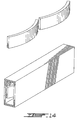
- the hockey shaft is fabricated in two longitudinal halves, each one having a rectangular or trapezoidal profile. When moulded, these two halves are curved (more as a bow) and secured into a permanent assembly side-by-side with the particularity to be back to back in a concave condition.
- the two halves After being compressed transversely, the two halves are permanently assembled by bonding, over wrapping or any other way.
- the final hockey shaft assembly will have the same visual aspect as a standard shaft but with the added property to be a pre-stressed hockey shaft (in flexural condition).
- the level of energy storage is directly related to the curvature amplitude, which is particular to each hockey shaft halves, combined to their inherent stiffness and strength.
- the rectangular shaft has uneven wall thicknesses and to counterbalance and pre-stress the shaft, wires are embedded inside the thinnest wall after being pre-stressed in tension.
- the internal profile of the cross section is not rectangular, but more in a parallelogram or trapezoidal shape with the result that the circumferential wall thicknesses is not uniform.
- wires would be pre-tensioned before being embedded in the thinnest wall section.
- the basic hockey shaft having a rectangular profile may be molded and curved (with linear recess) to be straightened and locked in place permanently with the use of two straight grooved molded planks.
- the result is a pre-stressed shaft permanently assembled with adhesive.
- this embodiment is a variation of the first embodiment with the difference that two spring inserts are used inside the rectangular shaft; these spring inserts are immersed and superposed to generate a counterbalancing pre-stress effect (asymmetric).
- this embodiment is a variation of the first embodiment with the difference that two springs inserts are used end-to-end allowing pre-stressing at asymmetric location and with asymmetric pre-stressing loads. Springs may be inserted in the vertical or in the horizontal plane.
- a first concept consists of a straight molded hockey shaft in which the secondary component (one or two spring-type pieces) is slid therein to generate more stiffness. This concept may be found in the above-described first, fifth and sixth embodiments.
- a second concept consists of a straight molded shaft having a variable wall thickness in cross-section and in which continuous wire reinforcements are admitted in one of the sides. This concept may be found in the third above-described embodiment.
- a third concept consists in a curved molded shaft in one or two molded pieces that are straightened and locked in place. This concept is found in the above first, second and fourth embodiment.
- the hockey stick consists in a single molded shaft that is locked in place (after straightening) with a secondary component installed inside or outside the tubular shaft and mounted in place.
- the hockey stick consists in two-molded half-size curved molded shaft that are bound back to back after straightening.
- a straight tubular hockey shaft When a straight tubular hockey shaft is molded, it possesses a particular rigidity resulting from its construction (fiber—polymer resin—fiber orientation—fiber/resin ratio—relative thicknesses of each layer of reinforcement—total thickness of shaft wall).
- the rigidity or stiffness factor being directly dependent of the elastic modulus (E) and surface inertia moment (I), its value may be raised without changing any of the variables list mentioned previously.
- a device is incorporated inside the shaft with the result that, under impact (slap shot), the shaft will deflect less and return the accumulated energy under deformation faster and quicker. The net result will be that the puck (with a constant energy input) leaves the blades quicker and travels faster.
- the device is basically a leaf spring, which, after a specific deformation, is slid and fixed inside the tubular shaft. Different spring rate can be obtained by varying, in a fixed geometry, the content of fiber and resin.
- a steel leaf spring has a very high modulus of elasticity; but, with carbon fiber embedded in a thermoset resin, it is possible to obtain superior value.
- the concept of using an asymmetric wall thickness has for objective to generate a hockey shaft having a different stiffness when used frontward and backward.
- composite material is used to keep weight at a minimum and stiffness at a maximum.
- High modulus carbon fibres are part of the solution.
- rigidity and stiffness of the hockey shaft is upgraded generating a quicker and faster puck release from the hockey blade, when compared to a conventional composite hockey shaft with pre-stressing in its tubular walls.
Landscapes
- Health & Medical Sciences (AREA)
- General Health & Medical Sciences (AREA)
- Physical Education & Sports Medicine (AREA)
- Laminated Bodies (AREA)
- Springs (AREA)
Abstract
Description
Claims (4)
Applications Claiming Priority (4)
| Application Number | Priority Date | Filing Date | Title |
|---|---|---|---|
| CA2,508,313 | 2005-05-25 | ||
| CA 2508313 CA2508313A1 (en) | 2005-05-25 | 2005-05-25 | Pre-stressed hockey shaft |
| CA2508313 | 2005-05-25 | ||
| PCT/CA2006/000848 WO2006125312A1 (en) | 2005-05-25 | 2006-05-24 | Pre-stressed hockey shaft |
Publications (2)
| Publication Number | Publication Date |
|---|---|
| US20080312012A1 US20080312012A1 (en) | 2008-12-18 |
| US7824283B2 true US7824283B2 (en) | 2010-11-02 |
Family
ID=37451444
Family Applications (1)
| Application Number | Title | Priority Date | Filing Date |
|---|---|---|---|
| US11/915,517 Expired - Fee Related US7824283B2 (en) | 2005-05-25 | 2006-05-24 | Pre-stressed hockey shaft |
Country Status (3)
| Country | Link |
|---|---|
| US (1) | US7824283B2 (en) |
| CA (2) | CA2508313A1 (en) |
| WO (1) | WO2006125312A1 (en) |
Families Citing this family (1)
| Publication number | Priority date | Publication date | Assignee | Title |
|---|---|---|---|---|
| US9511268B1 (en) * | 2015-06-02 | 2016-12-06 | Michael Levy | Stick assembly |
Citations (32)
| Publication number | Priority date | Publication date | Assignee | Title |
|---|---|---|---|---|
| US3813098A (en) | 1970-06-22 | 1974-05-28 | H Fischer | Prestressed elements |
| CA1061669A (en) | 1976-04-14 | 1979-09-04 | Yao T. Li | Archery bow |
| US4410183A (en) | 1982-09-13 | 1983-10-18 | Miller Jack V | Prestressed arrow shaft |
| CA1170287A (en) | 1981-04-03 | 1984-07-03 | T. Paul Jansen | Hockey stick shaft |
| US4629190A (en) * | 1984-04-17 | 1986-12-16 | Borgen Michael S | Hockey stick having arcuately bent shaft |
| US4685253A (en) * | 1981-03-06 | 1987-08-11 | Bitterly Jack G | Structural member |
| US5217221A (en) * | 1990-05-04 | 1993-06-08 | The Baum Research & Development Company, Inc. | Hockey stick formed of composite materials |
| US5259614A (en) | 1992-08-06 | 1993-11-09 | Greer Julian A | Composite seamless filament-wound golf club shaft and method |
| CA2166699A1 (en) | 1993-07-08 | 1995-01-19 | Leo Pesonen | Ice-hockey stick |
| CA2139556A1 (en) | 1994-01-07 | 1995-07-08 | Johannes Ossege | Crossbow for the shooting of arrows, bolts, harpoons or for narcoticizing purposes |
| EP0761419A1 (en) | 1995-08-28 | 1997-03-12 | Tsai Chen Soong | Shaft |
| WO1999020357A1 (en) | 1997-10-20 | 1999-04-29 | Schneider Terry L | Sports implement with enhanced energy transfer, control of flexion and vibration dampening |
| CA2266981A1 (en) | 1999-03-26 | 1999-09-16 | George Lorint | Arcuate shaft for sporting equipment |
| US6033327A (en) | 1998-07-16 | 2000-03-07 | Bird; Timothy E. | Variable rigidity hockey stick |
| US6113508A (en) | 1998-08-18 | 2000-09-05 | Alliance Design And Development Group | Adjusting stiffness and flexibility in sports equipment |
| WO2001043835A2 (en) | 1999-12-15 | 2001-06-21 | Charnnarong Laibangyang | Golf club with pre-tensioned shaft |
| US6257997B1 (en) | 1999-08-18 | 2001-07-10 | Alliance Design And Development Group | Adjusting stiffness and flexibility in sports equipment |
| US6361451B1 (en) * | 1998-09-21 | 2002-03-26 | Mide Technology Corporation | Variable stiffness shaft |
| US20020128093A1 (en) | 2001-01-23 | 2002-09-12 | Whayne James G. | Athletic equipment with improved force respones |
| US20020128087A1 (en) | 1997-02-19 | 2002-09-12 | Gordon Tilley | Golf club |
| US20030008734A1 (en) * | 2001-06-28 | 2003-01-09 | Montreal Sports Oy | Method for manufacturing shaft of stick, and shaft |
| US20030017884A1 (en) | 2001-03-30 | 2003-01-23 | Masters Brett P. | Golf club shaft with superelastic tensioning device |
| US20030100390A1 (en) | 2001-11-26 | 2003-05-29 | Alain Bellefleur | Shaft for a hockey stick |
| US20030144071A1 (en) | 2002-01-28 | 2003-07-31 | Dodge David J. | Sports equipment having a tubular structural member |
| US20030216197A1 (en) * | 2002-02-19 | 2003-11-20 | Lemire Laura E. | Vibration damping field hockey stick |
| US20030224870A1 (en) | 2002-05-28 | 2003-12-04 | Soong Tsai C. | Shaft having axial pre-stress |
| US20030224869A1 (en) | 2002-05-28 | 2003-12-04 | Soong Tsai C. | Shaft stiffened by axial pre-stress |
| CA2435340A1 (en) | 2002-11-05 | 2004-05-05 | Ray Blotteaux | Impact layer technology shaft |
| US20040214007A1 (en) * | 2003-04-23 | 2004-10-28 | Toray Composites (America), Inc. | Epoxy resin for fiber reinforced composite materials |
| US20050187046A1 (en) * | 2004-01-26 | 2005-08-25 | Kavanaugh Gerald W. | Hockey stick handle |
| US20060089215A1 (en) * | 2004-10-21 | 2006-04-27 | 2946-6380 Quebec Inc. | Hockey stick blade and a method of making thereof |
| US20060122013A1 (en) * | 2003-01-27 | 2006-06-08 | Dodge David J | Outer tubular reinforcement member |
-
2005
- 2005-05-25 CA CA 2508313 patent/CA2508313A1/en not_active Abandoned
-
2006
- 2006-05-24 WO PCT/CA2006/000848 patent/WO2006125312A1/en not_active Ceased
- 2006-05-24 CA CA2610023A patent/CA2610023C/en active Active
- 2006-05-24 US US11/915,517 patent/US7824283B2/en not_active Expired - Fee Related
Patent Citations (34)
| Publication number | Priority date | Publication date | Assignee | Title |
|---|---|---|---|---|
| US3813098A (en) | 1970-06-22 | 1974-05-28 | H Fischer | Prestressed elements |
| CA1061669A (en) | 1976-04-14 | 1979-09-04 | Yao T. Li | Archery bow |
| US4685253A (en) * | 1981-03-06 | 1987-08-11 | Bitterly Jack G | Structural member |
| CA1170287A (en) | 1981-04-03 | 1984-07-03 | T. Paul Jansen | Hockey stick shaft |
| US4410183A (en) | 1982-09-13 | 1983-10-18 | Miller Jack V | Prestressed arrow shaft |
| US4629190A (en) * | 1984-04-17 | 1986-12-16 | Borgen Michael S | Hockey stick having arcuately bent shaft |
| US5217221A (en) * | 1990-05-04 | 1993-06-08 | The Baum Research & Development Company, Inc. | Hockey stick formed of composite materials |
| US5259614A (en) | 1992-08-06 | 1993-11-09 | Greer Julian A | Composite seamless filament-wound golf club shaft and method |
| CA2166699A1 (en) | 1993-07-08 | 1995-01-19 | Leo Pesonen | Ice-hockey stick |
| CA2139556A1 (en) | 1994-01-07 | 1995-07-08 | Johannes Ossege | Crossbow for the shooting of arrows, bolts, harpoons or for narcoticizing purposes |
| EP0761419A1 (en) | 1995-08-28 | 1997-03-12 | Tsai Chen Soong | Shaft |
| US20020128087A1 (en) | 1997-02-19 | 2002-09-12 | Gordon Tilley | Golf club |
| WO1999020357A1 (en) | 1997-10-20 | 1999-04-29 | Schneider Terry L | Sports implement with enhanced energy transfer, control of flexion and vibration dampening |
| US6033327A (en) | 1998-07-16 | 2000-03-07 | Bird; Timothy E. | Variable rigidity hockey stick |
| US6113508A (en) | 1998-08-18 | 2000-09-05 | Alliance Design And Development Group | Adjusting stiffness and flexibility in sports equipment |
| US6361451B1 (en) * | 1998-09-21 | 2002-03-26 | Mide Technology Corporation | Variable stiffness shaft |
| CA2266981A1 (en) | 1999-03-26 | 1999-09-16 | George Lorint | Arcuate shaft for sporting equipment |
| US6257997B1 (en) | 1999-08-18 | 2001-07-10 | Alliance Design And Development Group | Adjusting stiffness and flexibility in sports equipment |
| WO2001043835A2 (en) | 1999-12-15 | 2001-06-21 | Charnnarong Laibangyang | Golf club with pre-tensioned shaft |
| US20020128093A1 (en) | 2001-01-23 | 2002-09-12 | Whayne James G. | Athletic equipment with improved force respones |
| US20030017884A1 (en) | 2001-03-30 | 2003-01-23 | Masters Brett P. | Golf club shaft with superelastic tensioning device |
| US20030008734A1 (en) * | 2001-06-28 | 2003-01-09 | Montreal Sports Oy | Method for manufacturing shaft of stick, and shaft |
| US20030100390A1 (en) | 2001-11-26 | 2003-05-29 | Alain Bellefleur | Shaft for a hockey stick |
| US20030144071A1 (en) | 2002-01-28 | 2003-07-31 | Dodge David J. | Sports equipment having a tubular structural member |
| US7140398B2 (en) * | 2002-01-28 | 2006-11-28 | Alliance Design And Development Group, Inc. | Sports equipment having a tubular structural member |
| US20030216197A1 (en) * | 2002-02-19 | 2003-11-20 | Lemire Laura E. | Vibration damping field hockey stick |
| US20030224869A1 (en) | 2002-05-28 | 2003-12-04 | Soong Tsai C. | Shaft stiffened by axial pre-stress |
| US20030224870A1 (en) | 2002-05-28 | 2003-12-04 | Soong Tsai C. | Shaft having axial pre-stress |
| CA2435340A1 (en) | 2002-11-05 | 2004-05-05 | Ray Blotteaux | Impact layer technology shaft |
| US20040102263A1 (en) * | 2002-11-05 | 2004-05-27 | Ray Blotteaux | Impact layer technology shaft |
| US20060122013A1 (en) * | 2003-01-27 | 2006-06-08 | Dodge David J | Outer tubular reinforcement member |
| US20040214007A1 (en) * | 2003-04-23 | 2004-10-28 | Toray Composites (America), Inc. | Epoxy resin for fiber reinforced composite materials |
| US20050187046A1 (en) * | 2004-01-26 | 2005-08-25 | Kavanaugh Gerald W. | Hockey stick handle |
| US20060089215A1 (en) * | 2004-10-21 | 2006-04-27 | 2946-6380 Quebec Inc. | Hockey stick blade and a method of making thereof |
Also Published As
| Publication number | Publication date |
|---|---|
| CA2610023C (en) | 2013-12-03 |
| CA2508313A1 (en) | 2006-11-25 |
| CA2610023A1 (en) | 2006-11-30 |
| WO2006125312A1 (en) | 2006-11-30 |
| US20080312012A1 (en) | 2008-12-18 |
Similar Documents
| Publication | Publication Date | Title |
|---|---|---|
| US7128669B2 (en) | Impact layer technology shaft | |
| US20050215364A1 (en) | Irregular hockey stick shaft and a method of fabrication thereof | |
| US10603556B2 (en) | Hockey-stick blade with tailored performance regions | |
| CN117379763A (en) | Pickleball racket and method capable of controlling ball retention | |
| US8448974B2 (en) | Board-like sliding device in the form of a ski or snowboard | |
| US4706985A (en) | Alpine ski with selective reinforcement | |
| IT9047802A1 (en) | STEM OF A GOLF BALL WITH SELECTIVE REINFORCEMENT POINTS. | |
| US5948472A (en) | Method for making a pultruded product | |
| RU2403940C2 (en) | Construction of hockey stick with multiple tubular structure | |
| KR101557615B1 (en) | Golf club shaft | |
| JP2022527035A (en) | Flexion spring element made of fiber plastic composite material | |
| US7824283B2 (en) | Pre-stressed hockey shaft | |
| US4556237A (en) | Alpine ski with selective reinforcement | |
| US4068861A (en) | Lightweight, flexible ski | |
| US4061106A (en) | Racing paddle and method of making the same | |
| US7185908B2 (en) | Downhill ski | |
| US20110206895A1 (en) | Carbon fiber laminate ski or snowboard with metal rib core dampening system | |
| WO2008155684A1 (en) | Billiard cue having a multiple tube structure | |
| JP6913711B2 (en) | Baseball or softball bat | |
| CA1145371A (en) | Hockey stick construction | |
| US20120178556A1 (en) | Hockey stick | |
| JPH057261U (en) | Golf club head | |
| Scott | A penetration mechanics study of compliant laminates | |
| CA2502642A1 (en) | Shaft for a hockey stick and method of fabrication therefor | |
| JPH0412152B2 (en) |
Legal Events
| Date | Code | Title | Description |
|---|---|---|---|
| AS | Assignment |
Owner name: 2946-6380 QUEBEC INC. A/S PRODUCTION P.H. ENR., CA Free format text: ASSIGNMENT OF ASSIGNORS INTEREST;ASSIGNORS:LUSSIER, REMI;JEAN, MARCEL;GATIEN, DANIEL;AND OTHERS;REEL/FRAME:021284/0751 Effective date: 20080222 |
|
| STCF | Information on status: patent grant |
Free format text: PATENTED CASE |
|
| FEPP | Fee payment procedure |
Free format text: PAYOR NUMBER ASSIGNED (ORIGINAL EVENT CODE: ASPN); ENTITY STATUS OF PATENT OWNER: LARGE ENTITY |
|
| FPAY | Fee payment |
Year of fee payment: 4 |
|
| AS | Assignment |
Owner name: SPORT MASKA INC., CANADA Free format text: ASSIGNMENT OF ASSIGNORS INTEREST;ASSIGNOR:INDUSTRIES ACM CANADA INC.;REEL/FRAME:041504/0928 Effective date: 20170116 Owner name: INDUSTRIES ACM CANADA INC., CANADA Free format text: MERGER;ASSIGNORS:A.C.M. COMPOSITES (1993) INC.;COMPOSANTES B.H.M INC.;2946-6380 QUEBEC INC.;REEL/FRAME:041909/0781 Effective date: 20140101 |
|
| AS | Assignment |
Owner name: CANADIAN IMPERIAL BANK OF COMMERCE, CANADA Free format text: SECURITY INTEREST;ASSIGNOR:SPORT MASKA INC.;REEL/FRAME:044050/0799 Effective date: 20170927 |
|
| FEPP | Fee payment procedure |
Free format text: ENTITY STATUS SET TO UNDISCOUNTED (ORIGINAL EVENT CODE: BIG.) |
|
| MAFP | Maintenance fee payment |
Free format text: PAYMENT OF MAINTENANCE FEE, 8TH YEAR, LARGE ENTITY (ORIGINAL EVENT CODE: M1552) Year of fee payment: 8 |
|
| AS | Assignment |
Owner name: CANADIAN IMPERIAL BANK OF COMMERCE, AS AGENT AND GRANTEE, CANADA Free format text: SECURITY INTEREST;ASSIGNOR:SPORT MASKA INC.;REEL/FRAME:058597/0573 Effective date: 20211223 |
|
| FEPP | Fee payment procedure |
Free format text: MAINTENANCE FEE REMINDER MAILED (ORIGINAL EVENT CODE: REM.); ENTITY STATUS OF PATENT OWNER: LARGE ENTITY |
|
| LAPS | Lapse for failure to pay maintenance fees |
Free format text: PATENT EXPIRED FOR FAILURE TO PAY MAINTENANCE FEES (ORIGINAL EVENT CODE: EXP.); ENTITY STATUS OF PATENT OWNER: LARGE ENTITY |
|
| STCH | Information on status: patent discontinuation |
Free format text: PATENT EXPIRED DUE TO NONPAYMENT OF MAINTENANCE FEES UNDER 37 CFR 1.362 |
|
| FP | Lapsed due to failure to pay maintenance fee |
Effective date: 20221102 |
|
| AS | Assignment |
Owner name: SPORT MASKA INC., CANADA Free format text: RELEASE BY SECURED PARTY;ASSIGNOR:CANADIAN IMPERIAL BANK OF COMMERCE;REEL/FRAME:069816/0766 Effective date: 20241231 Owner name: SPORT MASKA INC., CANADA Free format text: RELEASE OF SECURITY INTEREST;ASSIGNOR:CANADIAN IMPERIAL BANK OF COMMERCE;REEL/FRAME:069816/0766 Effective date: 20241231 |