US7823478B2 - Infinitely adjustable steering column assembly - Google Patents
Infinitely adjustable steering column assembly Download PDFInfo
- Publication number
- US7823478B2 US7823478B2 US11/527,039 US52703906A US7823478B2 US 7823478 B2 US7823478 B2 US 7823478B2 US 52703906 A US52703906 A US 52703906A US 7823478 B2 US7823478 B2 US 7823478B2
- Authority
- US
- United States
- Prior art keywords
- locking device
- outer jacket
- jacket
- inner jacket
- chamfer
- Prior art date
- Legal status (The legal status is an assumption and is not a legal conclusion. Google has not performed a legal analysis and makes no representation as to the accuracy of the status listed.)
- Expired - Fee Related, expires
Links
Images


Classifications
-
- B—PERFORMING OPERATIONS; TRANSPORTING
- B62—LAND VEHICLES FOR TRAVELLING OTHERWISE THAN ON RAILS
- B62D—MOTOR VEHICLES; TRAILERS
- B62D1/00—Steering controls, i.e. means for initiating a change of direction of the vehicle
- B62D1/02—Steering controls, i.e. means for initiating a change of direction of the vehicle vehicle-mounted
- B62D1/16—Steering columns
- B62D1/18—Steering columns yieldable or adjustable, e.g. tiltable
- B62D1/184—Mechanisms for locking columns at selected positions
Definitions
- the subject invention relates to adjustable steering column assemblies for vehicles.
- Steering column assemblies having a steering wheel that is adjustable telescopingly or tilting or both are well known in the automotive industry. Adjustable steering wheels provide both optimal and ergonomically correct positions of the steering wheel relative to a driver. Many conventional adjustable steering columns assemblies require separate locking mechanisms for the telescoping and tilting movement of the steering wheel, which is inconvenient for the driver.
- the subject invention provides an adjustable steering column assembly for a vehicle.
- the assembly comprises an outer jacket adapted to be mounted to the vehicle with the outer jacket defining a longitudinal axis.
- An inner jacket is coupled to the outer jacket and moves relative to the outer jacket along the axis between a plurality of longitudinal adjustment positions with the inner jacket having an abutment surface.
- a longitudinal locking device is supported by the outer jacket and moves between a released position allowing longitudinal movement of the inner jacket relative to the outer jacket along the axis and an engaged position preventing the longitudinal movement of the inner jacket relative to the outer jacket.
- a tilt housing is pivotally coupled to the inner jacket and moves relative to the inner jacket between a plurality of tilting adjustment positions.
- a tilt locking device is disposed between the inner jacket and the tilt housing and moves between a released position allowing tilting movement of the tilt housing relative to the inner jacket and an engaged position preventing the tilting movement of the tilt housing relative to the inner jacket.
- a control lever is movably mounted to the tilt housing and is coupled to both of the longitudinal locking device and the tilt locking device for moving the devices between the released and engaged positions.
- the longitudinal locking device has first and second members each having interengaging chamfers for facilitating movement of the first member into the engaged position.
- the first member has an engagement surface abutting the abutment surface of the inner jacket when in the engaged position to prevent the longitudinal movement of the inner jacket relative to the outer jacket.
- the subject invention also provides an adjustable steering column assembly having a uniquely configured longitudinal locking device.
- the longitudinal locking device has the first and second members with each having interengaging chamfers for facilitating movement of the first member into the engaged position.
- the first member has an engagement surface abutting the abutment surface of the inner jacket when in the engaged position with the engagement and abutment surfaces being uninterrupted along the longitudinal axis to provide an infinite number of adjustment positions for the inner jacket.
- the subject invention provides for an eloquent and simplified design of an adjustable steering column assembly having both longitudinal (telescoping) and tilting locking devices that are controlled by a single control lever. Also, the subject invention provides for an improved longitudinal locking device design which does not require the use of a rack and pinion arrangement.
- FIG. 1 is a perspective view of an adjustable steering column assembly in accordance with a first embodiment of the subject invention
- FIG. 2 is a cross-sectional view of the adjustable steering column assembly of FIG. 1 with a longitudinal locking device in an engaged position;
- FIG. 3 is a cross-sectional view of the adjustable steering column assembly of FIG. 1 with the longitudinal locking device in a released position;
- FIG. 4 is a perspective view of the adjustable steering column assembly of FIG. 1 with an outer jacket shown in phantom;
- FIG. 5 is a perspective view of an adjustable steering column assembly in accordance with a second embodiment of the subject invention.
- FIG. 6 is a partial cross-sectional view of the steering column assembly of FIG. 5 taken along line 6 - 6 of FIG. 5 ;
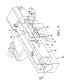
- FIG. 7 is an underside view of the adjustable steering column assembly in accordance with a third embodiment of the subject invention with an outer jacket shown in phantom and a longitudinal locking device in an engaged position;
- FIG. 8 is another underside view of the adjustable steering column of FIG. 7 with the outer jacket in phantom and the longitudinal locking device in a released position;
- FIG. 9 is a perspective view of an adjustable steering column assembly in accordance with a fourth embodiment of the subject invention with an outer jacket shown in phantom;
- FIG. 10 is a cross-sectional view of the adjustable steering column assembly of FIG. 9 taken along line 10 - 10 of FIG. 9 ;
- FIG. 11 is a cross-sectional view of the adjustable steering column assembly of FIG. 9 taken along line 11 - 11 of FIG. 9 .
- an adjustable steering column assembly for a vehicle in accordance with a first embodiment of the invention is shown at 20 in FIG. 1 .
- the adjustable steering column assembly 20 comprises an outer jacket 22 adapted to be mounted to the vehicle in any suitable manner.
- a steering shaft 24 which supports a steering wheel 26 , is coupled to the outer jacket 22 .
- the outer jacket 22 , steering shaft 24 , and steering wheel 26 may be of any suitable configuration as known in the art.
- a tilt housing 28 is pivotally coupled to the outer jacket 22 and moves relative to the outer jacket 22 between a plurality of tilting adjustment positions as is known in the art.
- the steering shaft 24 is also mounted to the tilt housing 28 and is also movable with the tilt housing 28 .
- the tilt housing 28 may be of any suitable configuration and is coupled to the outer jacket 22 through a tilting mechanism.
- a tilt locking device 30 is disposed between the outer jacket 22 and the tilt housing 28 and moves between a released position allowing tilting movement of the tilt housing 28 and an engaged position preventing the tilting movement of the tilt housing 28 . Tilting mechanisms and tilt locking devices are well known in the industry such that this mechanism and device will not be discussed in any greater detail.
- a control lever 32 is movably mounted to the tilt housing 28 .
- a cable 34 is interconnected between the control lever 32 and a longitudinal locking device 36 , which is discussed in greater detail below.
- the control lever 32 includes a first section 38 and a second section 40 with the cable 34 mounted to the first section 38 and the tilt locking device 30 coupled to the second section 40 .
- the coupling of the tilt locking device 30 to the control lever 32 is also known to those in the industry and will therefore not be discussed in any greater detail.
- the outer jacket 22 includes a bore 42 defining a longitudinal axis A.
- the outer jacket 22 also includes a vertical chamber 44 and a horizontal chamber 46 with the horizontal chamber 46 being open to the bore 42 of the outer jacket 22 .
- the vertical chamber 44 extends a majority of the height of the outer jacket 22 and the horizontal chamber 46 extends from the vertical chamber 44 to the bore 42 .
- An inner jacket 48 is coupled to the outer jacket 22 and moves relative to the outer jacket 22 along the axis A between a plurality of longitudinal adjustment positions.
- the inner jacket 48 may be of any suitable configuration and cooperates with the bore 42 to move in a telescoping fashion along the longitudinal axis A.
- the steering shaft 24 is mounted to the inner jacket 48 and is movable with the inner jacket 48 along the axis A.
- the inner jacket 48 has an abutment surface 50 , which is preferably inclined.
- the longitudinal locking device 36 is supported by the outer jacket 22 and moves between a released position allowing longitudinal movement of the inner jacket 48 relative to the outer jacket 22 along the axis A and an engaged position preventing the longitudinal movement of the inner jacket 48 relative to the outer jacket 22 .
- the longitudinal locking device 36 is disposed within the chambers 44 , 46 of the outer jacket 22 and partially extends into the bore 42 of the outer jacket 22 . The longitudinal locking device 36 will be discussed in greater detail below.
- the tilt housing 28 is also pivotally coupled to the inner jacket 48 and moves relative to the inner jacket 48 between the plurality of tilting adjustment positions.
- the tilt housing 28 is also coupled to the inner jacket 48 through the tilting mechanism.
- the tilt locking device 30 is disposed between the inner jacket 48 and the tilt housing 28 and moves between the released position allowing tilting movement of the tilt housing 28 relative to the inner jacket 48 and the engaged position preventing the tilting movement of the tilt housing 28 relative to the inner jacket 48 .
- the control lever 32 is coupled to both of the longitudinal locking device 36 and the tilt locking device 30 for simultaneously moving the devices 36 , 30 between the released and engaged positions.
- the cable 34 is interconnected between the control lever 32 and the longitudinal locking device 36 .
- the longitudinal locking device 36 includes a first member 52 that engages the inner jacket 48 and a second member 54 that is coupled to the control lever 32 .
- the first member 52 is disposed within the horizontal chamber 46 of the outer jacket 22 and at least partially extends into the bore 42 of the outer jacket 22 for movement within the horizontal chamber 46 and the bore 42 .
- the second member 54 is disposed within the vertical chamber 44 of the outer jacket 22 for movement within the vertical chamber 44 .
- Each of the first 52 and second 54 members have interengaging chamfers 56 , 58 for facilitating movement of the first member 52 into the engaged position with the inner jacket 48 .
- a length of the first 52 and second 54 members, as measured along the axis A, is substantially equal such that the chamfer 58 of the second member 54 engages a majority of the chamfer 56 of the first member 52 when in the engaged position.
- the first member 52 also has an engagement surface 60 abutting the abutment surface 50 of the inner jacket 48 when in the engaged position to prevent the longitudinal movement of the inner jacket 48 relative to the outer jacket 22 .
- the engagement surface 60 of the first member 52 is complementary in configuration with the abutment surface 50 of the inner jacket 48 .
- the engagement 60 and abutment 50 surfaces are inclined and are substantially parallel to each other when the first member 52 is in the engaged position. Hence, the engagement 60 and abutment 50 surfaces create a frictional effect between the first member 52 of the longitudinal locking device 36 and the inner jacket 48 for preventing the movement of the inner jacket 48 within the outer jacket 22 .
- the engagement 60 and abutment 50 surfaces are uninterrupted along the longitudinal axis A to provide an infinite number of adjustment positions for the inner jacket 48 .
- the engagement 60 and abutment 50 surfaces are substantially smooth relative to each other and are devoid of any teeth or interlocking configurations along the length of the longitudinal axis A. Therefore, friction is the primary force preventing movement of the inner jacket 48 relative to the outer jacket 22 when the longitudinal locking device 36 is in the engaged position.
- the chamfer 56 of the first member 52 is disposed on an opposing side of the first member 52 from the engagement surface 60 .
- the first member 52 also includes a top and a bottom with the chamfer 56 and the engagement surface 60 of the first member 52 each angled inwardly toward the top such that a width of the top is smaller than a width of the bottom.
- An angle between the bottom and the chamfer 56 of the first member 52 is different than an angle between the bottom and the engagement surface 60 of the first member 52 .
- the top and the bottom of the first member 52 have substantially flat parallel surfaces for defining a trapezoidal shaped first member 52 when viewed in cross-section.
- the second member 54 includes a ramp 62 disposed on an opposing side of the second member 54 from the chamfer 58 of the second member 54 with the ramp 62 engaging the outer jacket 22 .
- the second member 54 also includes a top and a bottom with the ramp 62 and the chamfer 58 of the second member 54 each angled inwardly toward the bottom such that a width of the bottom is smaller than a width of the top.
- An angle between the top and the ramp 62 of the second member 54 is substantially equal to an angle between the top and the chamfer 58 of the second member 54 .
- the top and the bottom of the second member 54 have substantially flat parallel surfaces for defining a trapezoidal shaped second member 54 when viewed in cross-section.
- a biasing device 64 reacts against the second member 54 to continuously bias the ramp 62 into engagement with the outer jacket 22 .
- the biasing device 64 also continuously biases the chamfer 58 of the second member 54 into engagement with the chamfer 56 of the first member 52 for continuously biasing the first member 52 into the engaged position with the inner jacket 48 .
- the biasing device 64 is further defined as a coil spring.
- the biasing device 64 is disposed within the vertical chamber 44 of the outer jacket 22 .
- a cap 66 is mounted to the outer jacket 22 over the vertical chamber 44 and the biasing device 64 such that the biasing device 64 reacts between the cap 66 and the second member 54 .
- the cable 34 is interconnected between the control lever 32 and the second member 54 for facilitating the movement of the second member 54 into the released position against the continuous bias of the biasing device 64 .
- the cable 34 extends through the cap 66 and the biasing device 64 and is connected to the top of the second member 54 .
- the control lever 32 is therefore coupled to the second member 54 through the cable 34 for moving the second member 54 into the released position against the continuous bias of the biasing device 64 .
- the biasing force of the biasing device 64 is selected to provide adequate biasing pressure to secure the inner jacket 48 to the outer jacket 22 while also being soft enough to allow actuation of cable 34 and movement of the second member 54 .
- a user actuates the control lever 32 to an unlocked position for simultaneously moving the longitudinal 36 and tilt 30 locking devices to the released positions.
- the cable 34 is pulled which in turn pulls the second member 54 upwardly against the bias of the biasing device 64 .
- the chamfer 58 of the second member 54 is now spaced from the chamfer 56 of the first member 52 .
- the first member 52 can therefore move to the released position in a linear fashion relative to the inner jacket 48 and transverse to the axis A, which reduces the frictional effect against the inner jacket 48 .
- the inner jacket 48 can now be moved telescopingly along the longitudinal axis A relative to the outer jacket 22 .
- the user actuates the control lever 32 to a locked position, which releases the pulling tension on the cable 34 .
- the biasing device 64 automatically biases the second member 54 downwardly into the vertical chamber 44 .
- the biasing of the second member 54 causes the ramp 62 to engage the outer jacket 22 simultaneously with the chamfer 58 of the second member 54 engaging the chamfer 56 of the first member 52 .
- the first member 52 is then biased to move to the engaged position with the inner jacket 48 in a linear fashion relative to the inner jacket 48 and transverse to the axis A.
- the biasing force or pressure of the biasing device 64 is amplified, which results in an adequate frictional effect being applied to the inner jacket 48 to secure the inner jacket 48 to the outer jacket 22 .
- the amplification of the biasing force or pressure also allows for the biasing device 64 to be selected such that the cable 34 can pull the second member 54 upward against the biasing force.
- FIGS. 5 and 6 a second embodiment of the adjustable steering column assembly 20 is shown wherein like numerals indicate like or corresponding parts.
- the primary difference between this embodiment and the embodiment of FIGS. 1-4 is the orientation of the longitudinal locking device 36 .
- the vertical chamber 44 within the outer jacket 22 is now orientated in a sideways substantially parallel relationship to the longitudinal axis A.
- the second member 54 and biasing device 64 are now sideways and substantially parallel with the longitudinal axis A. This orientation allows the cable 34 to be routed in a different direction (sideways) from the embodiment of FIGS. 1-4 .
- the change in orientation of the second member 54 in FIGS. 5 and 6 also changes the orientation of the ramp 62 and the chamfer 58 of the second member 54 . Accordingly, the chamfer 56 of the first member 52 must also change orientation in order to properly mesh with the chamfer 58 of the second member 54 .
- the chamfer 56 of the first member 52 remains disposed on an opposing side of the first member 52 from the engagement surface 60 , but the chamfer 56 and the engagement surface 60 of the first member 52 are angled in transverse directions. Specifically, the engagement surface 60 of the first member 52 is angled inwardly toward a top of the first member 52 with the chamfer 56 of the first member 52 being angled inwardly toward a side of the first member 52 .
- a height of the first 52 and second 54 members, as measured transverse to the axis A, is substantially equal such that the chamfer 58 of the second member 54 engages a majority of the chamfer 56 of the first member 52 when in the engaged position.
- the first member 52 also includes a notch 68 for providing adequate clearance for the biasing device 64 .
- FIGS. 7 and 8 a third embodiment of the adjustable steering column assembly 20 is shown wherein like numerals indicate like or corresponding parts.
- This embodiment orients the longitudinal locking device 36 in a similar manner as shown in the embodiment of FIGS. 5 and 6 .
- the primary difference with the embodiment of FIGS. 7 and 8 relates to the incorporation of a pivot pin 70 for pivotally connecting the first member 52 to the outer jacket 22 .
- the first member 52 can move between the released and engaged positions pivotally relative to the inner jacket 48 and the axis A.
- the incorporation of the pivot pin 70 reduces the likelihood of the first member 52 binding against the second member 54 when extreme loads are applied to the inner jacket 48 .
- FIGS. 9-11 a fourth embodiment of the adjustable steering Column assembly 20 is shown wherein like numerals indicate like or corresponding parts.
- the first 52 and second 54 members of the longitudinal locking device 36 are orientated in a manner similar to the longitudinal locking device 36 of FIGS. 1-4 .
- this embodiment incorporates an alternative biasing device 64 , which is in the form of a leaf spring.
- the biasing device 64 engages notches formed in the vertical chamber 44 of the outer jacket 22 and is continuously biased against the second member 54 .
- the cable 34 wraps around a post 72 that is mounted within the outer jacket 22 across the vertical chamber 44 .
- the cable 34 is turned and exits the vertical chamber 44 in a sideways orientation. Pulling of the cable 34 pulls the biasing device 64 upward and releases the biasing force against the second member 54 in a similar manner as described above.
Landscapes
- Engineering & Computer Science (AREA)
- Chemical & Material Sciences (AREA)
- Combustion & Propulsion (AREA)
- Transportation (AREA)
- Mechanical Engineering (AREA)
- Steering Controls (AREA)
Abstract
Description
Claims (9)
Priority Applications (4)
| Application Number | Priority Date | Filing Date | Title |
|---|---|---|---|
| US11/527,039 US7823478B2 (en) | 2006-09-26 | 2006-09-26 | Infinitely adjustable steering column assembly |
| EP07116562A EP1905665B1 (en) | 2006-09-26 | 2007-09-17 | Infinitely adjustable steering column assembly |
| AT07116562T ATE503672T1 (en) | 2006-09-26 | 2007-09-17 | INDEPENDENTLY ADJUSTABLE STEERING COLUMN ARRANGEMENT |
| DE602007013508T DE602007013508D1 (en) | 2006-09-26 | 2007-09-17 | Continuously adjustable steering column arrangement |
Applications Claiming Priority (1)
| Application Number | Priority Date | Filing Date | Title |
|---|---|---|---|
| US11/527,039 US7823478B2 (en) | 2006-09-26 | 2006-09-26 | Infinitely adjustable steering column assembly |
Publications (2)
| Publication Number | Publication Date |
|---|---|
| US20080072700A1 US20080072700A1 (en) | 2008-03-27 |
| US7823478B2 true US7823478B2 (en) | 2010-11-02 |
Family
ID=38779697
Family Applications (1)
| Application Number | Title | Priority Date | Filing Date |
|---|---|---|---|
| US11/527,039 Expired - Fee Related US7823478B2 (en) | 2006-09-26 | 2006-09-26 | Infinitely adjustable steering column assembly |
Country Status (4)
| Country | Link |
|---|---|
| US (1) | US7823478B2 (en) |
| EP (1) | EP1905665B1 (en) |
| AT (1) | ATE503672T1 (en) |
| DE (1) | DE602007013508D1 (en) |
Cited By (1)
| Publication number | Priority date | Publication date | Assignee | Title |
|---|---|---|---|---|
| US20250222973A1 (en) * | 2022-04-26 | 2025-07-10 | Nsk Steering Systems America, Inc. | Single radial wedge for steering column tube to housing de-lash |
Families Citing this family (3)
| Publication number | Priority date | Publication date | Assignee | Title |
|---|---|---|---|---|
| US7823479B2 (en) * | 2007-03-30 | 2010-11-02 | Nissan Technical Center North America, Inc. | Vehicle steering column structure |
| DE102007053672A1 (en) * | 2007-11-10 | 2009-05-20 | Daimler Ag | Steering column assembly for motor vehicles |
| DE102010037312B3 (en) | 2010-09-03 | 2012-01-12 | Thyssenkrupp Presta Ag | Steering column for a motor vehicle |
Citations (21)
| Publication number | Priority date | Publication date | Assignee | Title |
|---|---|---|---|---|
| US3491614A (en) * | 1968-07-18 | 1970-01-27 | Bendix Corp | Collapsible steering column |
| US3570322A (en) * | 1969-04-18 | 1971-03-16 | Robert A Krouse | Axially adjustable and collapsible steering column |
| US3962931A (en) | 1975-03-21 | 1976-06-15 | International Harvester Company | Telescopic steering column |
| US4195535A (en) | 1978-01-23 | 1980-04-01 | Eaton Corporation | Positioning device for a vehicle steering column |
| US4481838A (en) | 1982-04-19 | 1984-11-13 | Douglas Components Corporation | Adjustable steering shaft |
| US4554843A (en) | 1983-02-23 | 1985-11-26 | Affarsverket Ffv | Adjustable steering column support |
| US4607540A (en) | 1983-10-19 | 1986-08-26 | Fuji Kiko Company, Limited | Adjustable automotive steering column with adjustable tilt and top-position lock |
| US5029489A (en) | 1989-05-03 | 1991-07-09 | Lemforder Metallwaren Ag | Steering column with vertically adjustable steering wheel for motor vehicles |
| US5199319A (en) | 1991-02-15 | 1993-04-06 | Kabushiki Kaisha Yamada Seisakusho | Tilt telescopic steering device |
| US5492430A (en) * | 1994-10-14 | 1996-02-20 | Carl A. Hammoms | Telescopic tubes locking device |
| US5570610A (en) | 1995-06-30 | 1996-11-05 | General Motors Corporation | Adjustable steering column |
| US5626363A (en) | 1994-03-14 | 1997-05-06 | Dr. Ing. H.C.F. Porsche Ag | Adjustable steering device |
| US5823062A (en) | 1996-12-12 | 1998-10-20 | Chrysler Corporation | Tilt steering column lock |
| US5979265A (en) | 1997-09-11 | 1999-11-09 | Mando Machinery Corporation | Tilting and telescopic structure for steering columns |
| US6237439B1 (en) | 1999-09-09 | 2001-05-29 | Visteon Global Technologies, Inc. | Single release lever for steering column tilt and telescope |
| US6282977B1 (en) | 1997-10-28 | 2001-09-04 | Nsk Ltd. | Tilt adjusting-type steering apparatus |
| EP1211155A2 (en) | 2000-12-01 | 2002-06-05 | Mando Corporation | Position setting device for vehicle steering columns |
| US6460427B1 (en) | 2002-01-28 | 2002-10-08 | Ford Global Technologies, Inc. | Adjustment linkage for tilting and telescoping a steering column assembly |
| US20050183534A1 (en) | 2004-02-19 | 2005-08-25 | Maida Robert D. | Steering column assembly having single lever tilt and telescope adjustment |
| US20050269811A1 (en) | 2004-06-02 | 2005-12-08 | Schneider Douglas M | Telescope wedge locking mechanism |
| US7021660B2 (en) | 2002-09-30 | 2006-04-04 | Nsk Steering Systems America, Inc. | Adjustable steering column for motor vehicles |
Family Cites Families (1)
| Publication number | Priority date | Publication date | Assignee | Title |
|---|---|---|---|---|
| US6823062B2 (en) * | 2002-06-19 | 2004-11-23 | Avaya Technology Corp | Arrangement for predicting call-center status in a network call-routing system |
-
2006
- 2006-09-26 US US11/527,039 patent/US7823478B2/en not_active Expired - Fee Related
-
2007
- 2007-09-17 DE DE602007013508T patent/DE602007013508D1/en active Active
- 2007-09-17 EP EP07116562A patent/EP1905665B1/en not_active Not-in-force
- 2007-09-17 AT AT07116562T patent/ATE503672T1/en not_active IP Right Cessation
Patent Citations (22)
| Publication number | Priority date | Publication date | Assignee | Title |
|---|---|---|---|---|
| US3491614A (en) * | 1968-07-18 | 1970-01-27 | Bendix Corp | Collapsible steering column |
| US3570322A (en) * | 1969-04-18 | 1971-03-16 | Robert A Krouse | Axially adjustable and collapsible steering column |
| US3962931A (en) | 1975-03-21 | 1976-06-15 | International Harvester Company | Telescopic steering column |
| US4195535A (en) | 1978-01-23 | 1980-04-01 | Eaton Corporation | Positioning device for a vehicle steering column |
| US4481838A (en) | 1982-04-19 | 1984-11-13 | Douglas Components Corporation | Adjustable steering shaft |
| US4554843A (en) | 1983-02-23 | 1985-11-26 | Affarsverket Ffv | Adjustable steering column support |
| US4607540A (en) | 1983-10-19 | 1986-08-26 | Fuji Kiko Company, Limited | Adjustable automotive steering column with adjustable tilt and top-position lock |
| US5029489A (en) | 1989-05-03 | 1991-07-09 | Lemforder Metallwaren Ag | Steering column with vertically adjustable steering wheel for motor vehicles |
| US5199319A (en) | 1991-02-15 | 1993-04-06 | Kabushiki Kaisha Yamada Seisakusho | Tilt telescopic steering device |
| US5626363A (en) | 1994-03-14 | 1997-05-06 | Dr. Ing. H.C.F. Porsche Ag | Adjustable steering device |
| US5492430A (en) * | 1994-10-14 | 1996-02-20 | Carl A. Hammoms | Telescopic tubes locking device |
| US5570610A (en) | 1995-06-30 | 1996-11-05 | General Motors Corporation | Adjustable steering column |
| US5823062A (en) | 1996-12-12 | 1998-10-20 | Chrysler Corporation | Tilt steering column lock |
| US5979265A (en) | 1997-09-11 | 1999-11-09 | Mando Machinery Corporation | Tilting and telescopic structure for steering columns |
| US6282977B1 (en) | 1997-10-28 | 2001-09-04 | Nsk Ltd. | Tilt adjusting-type steering apparatus |
| US6237439B1 (en) | 1999-09-09 | 2001-05-29 | Visteon Global Technologies, Inc. | Single release lever for steering column tilt and telescope |
| EP1211155A2 (en) | 2000-12-01 | 2002-06-05 | Mando Corporation | Position setting device for vehicle steering columns |
| US20020066334A1 (en) * | 2000-12-01 | 2002-06-06 | Mando Corporation | Position setting device of steering column for vehicle |
| US6460427B1 (en) | 2002-01-28 | 2002-10-08 | Ford Global Technologies, Inc. | Adjustment linkage for tilting and telescoping a steering column assembly |
| US7021660B2 (en) | 2002-09-30 | 2006-04-04 | Nsk Steering Systems America, Inc. | Adjustable steering column for motor vehicles |
| US20050183534A1 (en) | 2004-02-19 | 2005-08-25 | Maida Robert D. | Steering column assembly having single lever tilt and telescope adjustment |
| US20050269811A1 (en) | 2004-06-02 | 2005-12-08 | Schneider Douglas M | Telescope wedge locking mechanism |
Cited By (2)
| Publication number | Priority date | Publication date | Assignee | Title |
|---|---|---|---|---|
| US20250222973A1 (en) * | 2022-04-26 | 2025-07-10 | Nsk Steering Systems America, Inc. | Single radial wedge for steering column tube to housing de-lash |
| US12491926B2 (en) * | 2022-04-26 | 2025-12-09 | Nsk Steering Systems America, Inc. | Single radial wedge for steering column tube to housing de-lash |
Also Published As
| Publication number | Publication date |
|---|---|
| US20080072700A1 (en) | 2008-03-27 |
| EP1905665B1 (en) | 2011-03-30 |
| DE602007013508D1 (en) | 2011-05-12 |
| EP1905665A2 (en) | 2008-04-02 |
| ATE503672T1 (en) | 2011-04-15 |
| EP1905665A3 (en) | 2009-04-01 |
Similar Documents
| Publication | Publication Date | Title |
|---|---|---|
| US8047096B2 (en) | Lock mechanism for an adjustable steering column assembly | |
| US6325196B1 (en) | Shifter with park lock and neutral lock device | |
| US20080238068A1 (en) | Vehicle steering column structure | |
| US8371188B2 (en) | Transmission control assembly having a locking mechanism | |
| US6390557B1 (en) | Reclining mechanism for vehicle seat | |
| US5452624A (en) | Tilt steering column locking mechanism | |
| EP1905665B1 (en) | Infinitely adjustable steering column assembly | |
| US8727369B2 (en) | Sliding hitch assembly | |
| CN100537325C (en) | Device for fixing an at least height-adjustable steering column | |
| US7069809B2 (en) | Vehicle tilt type steering device | |
| US7090250B2 (en) | Steering system with tilt control | |
| US7303210B2 (en) | Secure crank locking device for trailer landing gear assembly | |
| US7587959B2 (en) | Steering column assembly | |
| US8511703B2 (en) | Sliding hitch assembly | |
| CN100389998C (en) | Tilt steering device for vehicles | |
| EP1580460A2 (en) | A selector apparatus of an automatic transmission of vehicle | |
| JP4181912B2 (en) | Tilt telescopic steering column device | |
| US7823479B2 (en) | Vehicle steering column structure | |
| US7591757B2 (en) | Shift lever device | |
| EP3574737B1 (en) | Adjustment system for a steering assembly | |
| CN100500494C (en) | Tilt steering device for vehicles | |
| JPH0719334A (en) | Shift lock device of automatic transmission for vehicle | |
| CN119058801A (en) | Telescopic unlocking mechanism | |
| JP3636840B2 (en) | Shifting operation input device for automatic transmission | |
| JPH06241302A (en) | Tiltable shift operation lever for vehicle |
Legal Events
| Date | Code | Title | Description |
|---|---|---|---|
| AS | Assignment |
Owner name: DELPHI TECHNOLOGIES, INC., MICHIGAN Free format text: ASSIGNMENT OF ASSIGNORS INTEREST;ASSIGNORS:OHTSU, HITONOBU;NASH, RICHARD P.;RIEFE, RICHARD K.;REEL/FRAME:018348/0939;SIGNING DATES FROM 20060915 TO 20060918 Owner name: DELPHI TECHNOLOGIES, INC., MICHIGAN Free format text: ASSIGNMENT OF ASSIGNORS INTEREST;ASSIGNORS:OHTSU, HITONOBU;NASH, RICHARD P.;RIEFE, RICHARD K.;SIGNING DATES FROM 20060915 TO 20060918;REEL/FRAME:018348/0939 |
|
| AS | Assignment |
Owner name: GM GLOBAL TECHNOLOGY OPERATIONS, INC., MICHIGAN Free format text: ASSIGNMENT OF ASSIGNORS INTEREST;ASSIGNOR:DELPHI TECHNOLOGIES, INC.;REEL/FRAME:023449/0065 Effective date: 20091002 Owner name: GM GLOBAL TECHNOLOGY OPERATIONS, INC.,MICHIGAN Free format text: ASSIGNMENT OF ASSIGNORS INTEREST;ASSIGNOR:DELPHI TECHNOLOGIES, INC.;REEL/FRAME:023449/0065 Effective date: 20091002 |
|
| AS | Assignment |
Owner name: GM GLOBAL TECHNOLOGY OPERATIONS, INC.,MICHIGAN Free format text: ASSIGNMENT OF ASSIGNORS INTEREST;ASSIGNOR:DELPHI TECHNOLOGIES, INC.;REEL/FRAME:023988/0754 Effective date: 20091002 Owner name: UNITED STATES DEPARTMENT OF THE TREASURY,DISTRICT Free format text: SECURITY AGREEMENT;ASSIGNOR:GM GLOBAL TECHNOLOGY OPERATIONS, INC.;REEL/FRAME:023990/0349 Effective date: 20090710 Owner name: UAW RETIREE MEDICAL BENEFITS TRUST,MICHIGAN Free format text: SECURITY AGREEMENT;ASSIGNOR:GM GLOBAL TECHNOLOGY OPERATIONS, INC.;REEL/FRAME:023990/0831 Effective date: 20090710 Owner name: GM GLOBAL TECHNOLOGY OPERATIONS, INC., MICHIGAN Free format text: ASSIGNMENT OF ASSIGNORS INTEREST;ASSIGNOR:DELPHI TECHNOLOGIES, INC.;REEL/FRAME:023988/0754 Effective date: 20091002 Owner name: UNITED STATES DEPARTMENT OF THE TREASURY, DISTRICT Free format text: SECURITY AGREEMENT;ASSIGNOR:GM GLOBAL TECHNOLOGY OPERATIONS, INC.;REEL/FRAME:023990/0349 Effective date: 20090710 Owner name: UAW RETIREE MEDICAL BENEFITS TRUST, MICHIGAN Free format text: SECURITY AGREEMENT;ASSIGNOR:GM GLOBAL TECHNOLOGY OPERATIONS, INC.;REEL/FRAME:023990/0831 Effective date: 20090710 Owner name: UNITED STATES DEPARTMENT OF THE TREASURY, DISTRICT OF COLUMBIA Free format text: SECURITY AGREEMENT;ASSIGNOR:GM GLOBAL TECHNOLOGY OPERATIONS, INC.;REEL/FRAME:023990/0349 Effective date: 20090710 |
|
| AS | Assignment |
Owner name: GM GLOBAL TECHNOLOGY OPERATIONS, INC., MICHIGAN Free format text: RELEASE BY SECURED PARTY;ASSIGNOR:UNITED STATES DEPARTMENT OF THE TREASURY;REEL/FRAME:025386/0591 Effective date: 20100420 Owner name: GM GLOBAL TECHNOLOGY OPERATIONS, INC., MICHIGAN Free format text: RELEASE BY SECURED PARTY;ASSIGNOR:UAW RETIREE MEDICAL BENEFITS TRUST;REEL/FRAME:025386/0503 Effective date: 20101026 |
|
| AS | Assignment |
Owner name: GM GLOBAL TECHNOLOGY OPERATIONS, INC., MICHIGAN Free format text: ASSIGNMENT OF ASSIGNORS INTEREST;ASSIGNOR:GM GLOBAL TECHNOLOGY OPERATIONS, INC.;REEL/FRAME:027842/0918 Effective date: 20101130 Owner name: PACIFIC CENTURY MOTORS, INC., CHINA Free format text: ASSIGNMENT OF ASSIGNORS INTEREST;ASSIGNOR:GM GLOBAL TECHNOLOGY OPERATIONS, INC.;REEL/FRAME:027842/0918 Effective date: 20101130 |
|
| AS | Assignment |
Owner name: STEERING SOLUTIONS IP HOLDING CORPORATION, MICHIGA Free format text: ASSIGNMENT OF ASSIGNORS INTEREST;ASSIGNORS:PACIFIC CENTURY MOTORS, INC.;NEXTEER (BEIJING) TECHNOLOGY CO., LTD.;REEL/FRAME:027870/0666 Effective date: 20120126 |
|
| REMI | Maintenance fee reminder mailed | ||
| LAPS | Lapse for failure to pay maintenance fees | ||
| STCH | Information on status: patent discontinuation |
Free format text: PATENT EXPIRED DUE TO NONPAYMENT OF MAINTENANCE FEES UNDER 37 CFR 1.362 |
|
| STCH | Information on status: patent discontinuation |
Free format text: PATENT EXPIRED DUE TO NONPAYMENT OF MAINTENANCE FEES UNDER 37 CFR 1.362 |
|
| FP | Lapsed due to failure to pay maintenance fee |
Effective date: 20141102 |