US7817185B2 - Image processing device, image processing method, image pickup device, and image pickup method for superimposing a plurality of pictures on each other - Google Patents
Image processing device, image processing method, image pickup device, and image pickup method for superimposing a plurality of pictures on each other Download PDFInfo
- Publication number
- US7817185B2 US7817185B2 US11/757,134 US75713407A US7817185B2 US 7817185 B2 US7817185 B2 US 7817185B2 US 75713407 A US75713407 A US 75713407A US 7817185 B2 US7817185 B2 US 7817185B2
- Authority
- US
- United States
- Prior art keywords
- per
- motion vector
- calculating
- pictures
- translation
- Prior art date
- Legal status (The legal status is an assumption and is not a legal conclusion. Google has not performed a legal analysis and makes no representation as to the accuracy of the status listed.)
- Expired - Fee Related, expires
Links
Images


Classifications
-
- H—ELECTRICITY
- H04—ELECTRIC COMMUNICATION TECHNIQUE
- H04N—PICTORIAL COMMUNICATION, e.g. TELEVISION
- H04N23/00—Cameras or camera modules comprising electronic image sensors; Control thereof
- H04N23/60—Control of cameras or camera modules
- H04N23/68—Control of cameras or camera modules for stable pick-up of the scene, e.g. compensating for camera body vibrations
-
- H—ELECTRICITY
- H04—ELECTRIC COMMUNICATION TECHNIQUE
- H04N—PICTORIAL COMMUNICATION, e.g. TELEVISION
- H04N19/00—Methods or arrangements for coding, decoding, compressing or decompressing digital video signals
- H04N19/50—Methods or arrangements for coding, decoding, compressing or decompressing digital video signals using predictive coding
- H04N19/503—Methods or arrangements for coding, decoding, compressing or decompressing digital video signals using predictive coding involving temporal prediction
- H04N19/51—Motion estimation or motion compensation
- H04N19/513—Processing of motion vectors
-
- G—PHYSICS
- G06—COMPUTING; CALCULATING OR COUNTING
- G06T—IMAGE DATA PROCESSING OR GENERATION, IN GENERAL
- G06T7/00—Image analysis
- G06T7/20—Analysis of motion
- G06T7/223—Analysis of motion using block-matching
-
- H—ELECTRICITY
- H04—ELECTRIC COMMUNICATION TECHNIQUE
- H04N—PICTORIAL COMMUNICATION, e.g. TELEVISION
- H04N19/00—Methods or arrangements for coding, decoding, compressing or decompressing digital video signals
- H04N19/42—Methods or arrangements for coding, decoding, compressing or decompressing digital video signals characterised by implementation details or hardware specially adapted for video compression or decompression, e.g. dedicated software implementation
- H04N19/43—Hardware specially adapted for motion estimation or compensation
-
- H—ELECTRICITY
- H04—ELECTRIC COMMUNICATION TECHNIQUE
- H04N—PICTORIAL COMMUNICATION, e.g. TELEVISION
- H04N19/00—Methods or arrangements for coding, decoding, compressing or decompressing digital video signals
- H04N19/50—Methods or arrangements for coding, decoding, compressing or decompressing digital video signals using predictive coding
- H04N19/503—Methods or arrangements for coding, decoding, compressing or decompressing digital video signals using predictive coding involving temporal prediction
- H04N19/51—Motion estimation or motion compensation
- H04N19/527—Global motion vector estimation
-
- H—ELECTRICITY
- H04—ELECTRIC COMMUNICATION TECHNIQUE
- H04N—PICTORIAL COMMUNICATION, e.g. TELEVISION
- H04N19/00—Methods or arrangements for coding, decoding, compressing or decompressing digital video signals
- H04N19/50—Methods or arrangements for coding, decoding, compressing or decompressing digital video signals using predictive coding
- H04N19/503—Methods or arrangements for coding, decoding, compressing or decompressing digital video signals using predictive coding involving temporal prediction
- H04N19/51—Motion estimation or motion compensation
- H04N19/533—Motion estimation using multistep search, e.g. 2D-log search or one-at-a-time search [OTS]
-
- H—ELECTRICITY
- H04—ELECTRIC COMMUNICATION TECHNIQUE
- H04N—PICTORIAL COMMUNICATION, e.g. TELEVISION
- H04N19/00—Methods or arrangements for coding, decoding, compressing or decompressing digital video signals
- H04N19/50—Methods or arrangements for coding, decoding, compressing or decompressing digital video signals using predictive coding
- H04N19/503—Methods or arrangements for coding, decoding, compressing or decompressing digital video signals using predictive coding involving temporal prediction
- H04N19/51—Motion estimation or motion compensation
- H04N19/537—Motion estimation other than block-based
-
- H—ELECTRICITY
- H04—ELECTRIC COMMUNICATION TECHNIQUE
- H04N—PICTORIAL COMMUNICATION, e.g. TELEVISION
- H04N19/00—Methods or arrangements for coding, decoding, compressing or decompressing digital video signals
- H04N19/50—Methods or arrangements for coding, decoding, compressing or decompressing digital video signals using predictive coding
- H04N19/59—Methods or arrangements for coding, decoding, compressing or decompressing digital video signals using predictive coding involving spatial sub-sampling or interpolation, e.g. alteration of picture size or resolution
-
- H—ELECTRICITY
- H04—ELECTRIC COMMUNICATION TECHNIQUE
- H04N—PICTORIAL COMMUNICATION, e.g. TELEVISION
- H04N19/00—Methods or arrangements for coding, decoding, compressing or decompressing digital video signals
- H04N19/80—Details of filtering operations specially adapted for video compression, e.g. for pixel interpolation
-
- H—ELECTRICITY
- H04—ELECTRIC COMMUNICATION TECHNIQUE
- H04N—PICTORIAL COMMUNICATION, e.g. TELEVISION
- H04N23/00—Cameras or camera modules comprising electronic image sensors; Control thereof
- H04N23/60—Control of cameras or camera modules
- H04N23/68—Control of cameras or camera modules for stable pick-up of the scene, e.g. compensating for camera body vibrations
- H04N23/681—Motion detection
- H04N23/6811—Motion detection based on the image signal
Definitions
- the present disclosure relates to an image processing device, an image processing method, an image pickup device, and an image pickup method that can correct a so-called hand movement component included in image information obtained by image pickup in an image pickup device such as a digital still camera or a video camera, for example, and thereby obtain an image free from the hand movement component.
- vibration of the image pickup device due to hand movement at the time of the photographing appears as a vibration in a picture unit of a picked-up image.
- optical hand movement correction systems using a gyro (angular velocity) sensor have been dominant in the recent market with a reduction in cost, an improvement in performance, and a reduction in size of the gyro sensor.
- Hand movement corrections used for still images in devices for consumer use currently available on the market all measure a hand movement vector using a gyro sensor or an acceleration sensor, and feed back the hand movement vector to a mechanism system to perform high-speed control so as to prevent blurring of an image projected on an image sensor such as a CCD (Charge Coupled Device) imager, a CMOS (Complementary Metal Oxide Semiconductor) imager or the like.
- CCD Charge Coupled Device
- CMOS Complementary Metal Oxide Semiconductor
- a lens Proposed as the mechanism system referred to here is a lens, a prism, or an imager (or a module integral with the imager), and control of the lens, the prism, or the imager is referred to as a lens shift, a prism shift, or an imager shift, respectively.
- the hand movement corrections using sensors in the present situation have a serious problem of being unable to increase precision in principle, the hand movement corrections are valued highly in the market because the hand movement corrections are short of correcting hand movement but are able to reduce hand movement.
- a sensorless hand movement correction method which calculates a motion vector of a picture unit of the picked-up image, and shifts reading positions of picked-up image data stored in an image memory on the basis of the motion vector, thereby making hand movement correction.
- a sensorless hand movement correction method using this block matching also has advantages of being able to detect a hand movement vector with a pixel precision including a rotation component in a roll-axis direction in principle and making it possible to reduce size and weight of an image pickup device because a need for mechanical parts such as a gyro sensor and the like is eliminated.
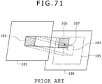
- FIG. 71 and FIG. 72 show a schematic representation of an outline of block matching.
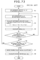
- FIG. 73 is a typical example of a flowchart of a block matching process.
- Block matching is a method that calculates a motion vector in a unit of one picture between a reference picture of picked-up images from an image pickup device unit as a picture of interest and an original picture as a picked-up image picture preceding the reference picture by one picture, for example, by calculating correlation between the reference picture and the original picture in blocks as rectangular regions of predetermined size.
- a picture in this case refers to an image formed by image data of one frame or one field
- a picture is formed by one frame, and a picture is referred to as a frame.
- a reference picture is referred to as a reference frame
- an original picture will be referred to as an original frame (target frame).
- the image data of the reference frame is the image data of a present frame from the image pickup device unit, or image data obtained by storing the image data of a present frame in a frame memory and delaying the image data by one frame.
- the image data of the original frame is image data obtained by further storing the image data of the reference frame in a frame memory and delaying the image data by one frame.
- a target block 103 formed by a rectangular region of a predetermined size including a plurality of pixels in a horizontal direction and a plurality of lines in a vertical direction is set at an arbitrary predetermined position in the original frame 101 .
- a projected image block 104 (see a dotted line in FIG. 71 ) of the target block is assumed at the same position as the position of the target block 103 in the original frame
- a search range 105 (see alternate long and short dash lines in FIG. 71 ) is set with the projected image block 104 of the target block as a center
- a reference block 106 having the same size as the target block 103 is considered.
- the reference block 106 is moved to positions within the search range 105 in the reference frame 102 . Correlation between image contents included in the reference block 106 at each of the positions and image contents of the target block 103 is determined. The position of the reference block 106 at which position the correlation is strongest is detected as a position to which the target block 103 in the original frame is moved in the reference frame 102 . Then, an amount of positional displacement between the detected position of the reference block 106 and the position of the target block is detected as a motion vector as a quantity including a direction component.
- the reference block 106 is moved in the search range 105 by a unit of one pixel or a plurality of pixels in the horizontal direction and the vertical direction, for example. Hence, a plurality of reference blocks are set within the search range 105 .
- the correlation between the target block 103 and the reference block 106 moved within the search range 105 is detected by obtaining a sum total of absolute values of differences between the luminance values of all pixels within the target block 103 and the luminance values of corresponding pixels within the reference block 106 (the sum total of the absolute values of the differences will be referred to as a difference absolute value sum, and the difference absolute value sum will hereinafter be described as a SAD (Sum of Absolute Difference) value). That is, the reference block 106 at a position of a minimum SAD value is detected as a reference block having the strongest correlation, and an amount of positional displacement of the detected reference block 106 with respect to the position of the target block 103 is detected as a motion vector.
- SAD Sud of Absolute Difference
- an amount of positional displacement of each of a plurality of reference blocks 106 set within the search range 105 with respect to the position of the target block 103 is represented by a reference vector 107 (see FIG. 71 ) as a quantity including a direction component.
- the reference vector 107 of each reference block 106 has a value corresponding to the position of the reference block 106 in the reference frame 102 .
- the reference vector of the reference block 106 from which a minimum SAD value is obtained is detected as a motion vector corresponding to the target block 103 .
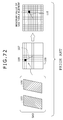
- SAD values between a plurality of respective reference blocks 106 set within the search range 105 and the target block 103 are stored in a memory in correspondence with respective reference vectors 107 corresponding to the positions of the respective reference blocks 106 within the search range 105 .
- a reference block 106 having a minimum SAD value among the SAD values of all the reference blocks 106 which SAD values are stored in the memory is detected. Thereby the motion vector 110 corresponding to the target block 103 is detected.
- a table in which the SAD values of the respective reference blocks 106 are stored in correspondence with the respective reference vectors 107 corresponding to the positions of the plurality of reference blocks 106 set within the search range 105 is referred to as a difference absolute value sum table (hereinafter referred to as a SAD table).
- a SAD table 108 in FIG. 72 illustrates this table.
- the SAD values of the respective reference blocks 106 in the SAD table 108 are referred to as SAD table elements 109 .
- the positions of the target block 103 and the reference blocks 106 refer to arbitrary specific positions, for example central positions of the blocks.
- a reference vector 107 indicates an amount of displacement (including a direction) between the position of the projected image block 104 of the target block 103 and the position of the reference block 106 in the reference frame 102 .
- the target block 103 is situated at the central position of the frame.
- the reference vectors 107 corresponding to the respective reference blocks 106 represent displacements of the positions of the respective reference blocks 106 with respect to the position corresponding to the target block 103 in the reference frame 102 . Therefore, when the position of a reference block 106 is specified, the value of the reference vector corresponding to the position is also specified. Hence, when the address of the SAD table element of a reference block in the memory of the SAD table 108 is specified, the corresponding reference vector is specified.
- one reference block Ii within the search range 105 is specified. This is equivalent to specifying the reference vector corresponding to the reference block Ii (step S 1 ).
- (vx, vy) denotes a position indicated by the specified reference vector when the position of the target block in the frame is set as a reference position (0, 0).
- vx is a component of an amount of displacement by the specified reference vector from the reference position in the horizontal direction.
- vy is a component of an amount of displacement by the specified reference vector from the reference position in the vertical direction.
- the amounts of displacement vx and vy are values in units of pixels.
- (vx, vy) denotes the position indicated by a reference vector with respect to the reference position (hereinafter referred to as the position indicated by the reference vector for simplicity), and corresponds to each reference vector. That is, supposing that vx and vy are integers, (vx, vy) represents each reference vector.
- a reference vector indicating the position (vx, vy) may be described as a reference vector (vx, vy).
- the search range is expressed as ⁇ Rx ⁇ vx ⁇ +Rx, ⁇ Ry ⁇ vy ⁇ +Ry
- step S 2 coordinates (x, y) of one pixel within the target block Io are specified (step S 2 ).
- the SAD value is then written to the address indicated by the reference vector (vx, vy).
- step S 5 whether the above-described operation has been performed for pixels at all coordinates (x, y) within the target block Io is determined.
- the process returns to step S 2 to specify a pixel position at next coordinates (x, y) within the target block Io and repeat the process from step S 2 on down.
- step S 6 When it is determined in step S 6 that there is a reference vector (vx, vy) for which the above-described operation process has not yet been completed, the process returns to step S 1 to set the next reference vector (vx, vy) for which the above-described operation process has not been completed, and the process repeats from step S 1 on down.
- step S 6 when it is determined in step S 6 that there is no reference vector (vx, vy) for which the above-described operation process has not been completed within the search range, it is determined that a SAD table is completed.
- a minimum SAD value is detected in the completed SAD table (step S 7 ).
- a reference vector corresponding to an address of the minimum SAD value is detected as a motion vector corresponding to the target block Io (step S 8 ).
- the minimum SAD value is written as SAD (mx, my)
- the intended motion vector is calculated as a vector (mx, my) indicating a position (mx, my).
- search ranges 105 , 105 , . . . are set for projected images 104 , 104 , . . . of the plurality of target blocks, respectively, and motion vectors 110 , 110 , . . . corresponding to the target blocks are detected in the respective search ranges.
- the hand movement vector (global motion vector) of the reference frame with respect to the original frame is detected from the plurality of detected motion vectors 110 , 110 , . . . .
- a method for detecting the hand movement vector (global motion vector) from the plurality of motion vectors 110 As a main method for detecting the hand movement vector (global motion vector) from the plurality of motion vectors 110 , a method has been proposed which makes a majority decision based on the plurality of motion vectors, that is, which sets a maximum number of motion vectors that are equal to each other in direction and magnitude among the plurality of motion vectors 110 as global motion vector.
- a method combining the method of majority decision with reliability evaluation based on an amount of change (frequency) of the motion vector in a direction of a time axis has been proposed.
- Patent Document 1 Japanese Patent Laid-Open No. 2003-78807
- Patent Document 2 Japanese Patent Laid-Open No. Hei 7-283999
- This Patent Document 2 is an algorithm of consecutively taking still images in short exposure times such that a hand movement component is not produced, obtaining hand movement vectors between the still images, adding together the plurality of still images taken consecutively while moving the still images according to the hand movement vectors, and finally obtaining a high picture quality (high resolution) still image free from hand movement components and low illuminance noise.
- Patent Document 3 Japanese Patent Laid-Open No. 2005-38396 can be recited as a practical proposal on a feasible level.
- a device disclosed in Patent Document 3 includes means for obtaining a motion vector in a size resulting from reducing conversion of an image and means for sharing an identical SAD table between a plurality of blocks.
- the reducing conversion of an image and the sharing of a SAD table between a plurality of blocks are a very good method for realizing reduction of SAD table size, and are used in other fields for motion vector detection and scene change detection in an MPEG (Moving Picture Experts Group) image compression system, for example.
- MPEG Motion Picture Experts Group
- Patent Document 3 has problems in that the reducing conversion of an image and memory (DRAM (Dynamic RAM (Random Access Memory))) access at the time of the reducing conversion consume time and memory space, and because the plurality of blocks make time-division access to the SAD table, memory access is greatly increased and this process also takes time. Real-time performance and reduction of a system delay time are both required in hand movement correction for moving images, and therefore the process time becomes a problem.
- DRAM Dynamic RAM (Random Access Memory)
- the reducing conversion of an original image requires that a low-pass filter for removing aliasing (folding distortion) and low illuminance noise be implemented as preprocessing for the reduction process.
- characteristics of the low-pass filter are changed according to a reduction scaling factor, and especially when a low-pass filter in a vertical direction is a multiple-tap digital filter, many line memories and operation logics are required, thus presenting a problem of an increase in circuit scale.
- an image processing device including: per-block motion vector calculating means for calculating a motion vector between two pictures of an image input in picture units sequentially, performing block matching in each of divided regions obtained by dividing one picture into a plurality of regions, and calculating per-block motion vectors for the respective divided regions; translation amount calculating means for calculating an amount of translation of the other of the two pictures with respect to one of the two pictures from a plurality of the per-block motion vectors calculated by the per-block motion vector calculating means; rotation angle calculating means for calculating a rotation angle of the other of the two pictures with respect to one of the two pictures from the plurality of the per-block motion vectors calculated by the per-block motion vector calculating means; and rotation and translation adding means for superimposing a plurality of pictures on each other using the amount of translation calculated by the translation amount calculating means and the rotation angle calculated by the rotation angle calculating means.
- the amount of translation and the rotation angle of the reference picture with respect to the original picture are calculated from the plurality of per-block motion vectors calculated by the per-block motion vector calculating means. Then, using the calculated amount of translation and the calculated rotation angle, the plurality of pictures are superimposed sequentially.
- An image as a result of the superimposition is an image of high picture quality from which a hand movement component is removed when the image is a picked-up image, for example.
- the image processing device further includes: global motion vector calculating means for calculating a global motion vector of a whole of the other of the two pictures with respect to one of the two pictures; and evaluating means for evaluating each of the plurality of per-block motion vectors obtained by the per-block motion vector calculating means, using the global motion vector; wherein the other of the two pictures in which picture a number of per-block motion vectors given a high evaluation value by the evaluating means is smaller than a predetermined threshold value is excluded from the pictures superimposed on each other by the rotation and translation adding means.
- each of the plurality of per-block motion vectors is evaluated using the global motion vector of the whole of the reference picture with respect to the original picture, and the reference picture of low reliability in which the number of per-block motion vectors given a high evaluation value is smaller than a predetermined threshold value is excluded from the pictures superimposed on each other by the rotation and translation adding means.
- the image processing device further includes: global motion vector calculating means for calculating a global motion vector of a whole of the other of the two pictures with respect to one of the two pictures; and evaluating means for evaluating each of the plurality of per-block motion vectors obtained by the per-block motion vector calculating means, using the global motion vector; wherein the translation amount calculating means and the rotation angle calculating means calculate the amount of translation and the rotation angle from only a plurality of per-block motion vectors given a high evaluation value by the evaluating means.
- the amount of translation and the rotation angle are calculated using only per-block motion vectors of high reliability among the per-block motion vectors calculated by the per-block motion vector calculating means, so that an accurate amount of translation and an accurate rotation angle are calculated.
- the rotation and translation adding means superimposes reference pictures on each other using the accurate amount of translation and the accurate rotation angle. It can be expected that an image of higher picture quality free from a hand movement component will be obtained.
- the amount of translation and the rotation angle of the reference picture with respect to the original picture are calculated from the plurality of per-block motion vectors of the reference picture, the per-block motion vectors being calculated by the per-block motion vector calculating means.
- the plurality of pictures are superimposed sequentially.
- An image as a result of the superimposition is an image of high picture quality from which a hand movement component is removed when the image is a picked-up image, for example.
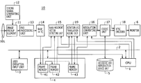
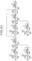
- FIG. 1 is a block diagram showing an example of configuration of a first embodiment of an image processing device
- FIG. 2 is a diagram of assistance in explaining an outline of an embodiment of an image processing method
- FIG. 3 is a diagram of assistance in explaining the outline of the embodiment of the image processing method
- FIG. 4 is a diagram of assistance in explaining the outline of the embodiment of the image processing method
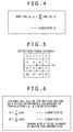
- FIG. 5 is a diagram of assistance in explaining a process of calculating the hand movement translation component of a frame in the embodiment of the image processing method
- FIG. 6 is a diagram of assistance in explaining the process of calculating the hand movement translation component of the frame in the embodiment of the image processing method
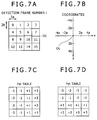
- FIGS. 7A , 7 B, 7 C, and 7 D are diagrams of assistance in explaining a process of calculating the hand movement rotation component of a frame in the embodiment of the image processing method
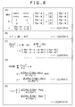
- FIGS. 8(A) , 8 (B), 8 (C), 8 (D), and 8 (E) are diagrams of assistance in explaining the process of calculating the hand movement rotation component of the frame in the embodiment of the image processing method;
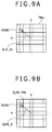
- FIGS. 9A and 9B are diagrams of assistance in explaining an outline of an embodiment of the image processing method
- FIG. 10 is a diagram of assistance in explaining an outline of an embodiment of the image processing method.
- FIG. 11 is a flowchart of assistance in explaining the outline of the embodiment of the image processing method.
- FIGS. 12A and 12B are diagrams of assistance in explaining an example of a process of calculating a per-block motion vector in a plurality of stages in an embodiment of the image processing method according;
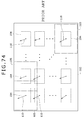
- FIG. 13 is a diagram of assistance in explaining an example of a process of calculating a per-block motion vector in an embodiment of the image processing method
- FIGS. 14A and 14B are diagrams of assistance in explaining an example of a process of calculating a per-block motion vector in an embodiment of the image processing method
- FIG. 15 is a diagram of assistance in explaining an example of a process of calculating a per-block motion vector in an embodiment of the image processing method
- FIGS. 16A and 16B are diagrams of assistance in explaining an example of a process of calculating a per-block motion vector in an embodiment of the image processing method
- FIG. 17 is a diagram of assistance in explaining an example of a process of calculating a per-block motion vector in an embodiment of the image processing method
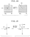
- FIG. 18 is a diagram of assistance in explaining an example of a process of calculating a per-block motion vector in an embodiment of the image processing method
- FIG. 19 is a diagram of assistance in explaining an example of a process of calculating a per-block motion vector in an embodiment of the image processing method
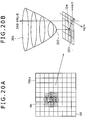
- FIGS. 20A and 20B are diagrams of assistance in explaining an example of a process of calculating a per-block motion vector in an embodiment of the image processing method
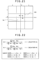
- FIG. 21 is a diagram of assistance in explaining an example of a process of calculating a per-block motion vector in an embodiment of the image processing method
- FIG. 22 is a diagram of assistance in explaining an example of a process of calculating a per-block motion vector in an embodiment of the image processing method
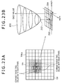
- FIGS. 23A and 23B are diagrams of assistance in explaining an example of a process of calculating a per-block motion vector in an embodiment of the image processing method
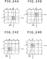
- FIGS. 24A , 24 B, 24 C, and 24 D are diagrams of assistance in explaining an example of a process of calculating a per-block motion vector in an embodiment of the image processing method
- FIG. 25 is a diagram of assistance in explaining an example of a process of calculating a per-block motion vector in an embodiment of the image processing method
- FIG. 26 is a diagram of assistance in explaining an example of a process of calculating a per-block motion vector in an embodiment of the image processing method
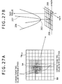
- FIGS. 27A and 27B are diagrams of assistance in explaining an example of a process of calculating a per-block motion vector in an embodiment of the image processing method
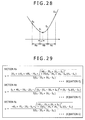
- FIG. 28 is a diagram of assistance in explaining an example of a process of calculating a per-block motion vector in an embodiment of the image processing method
- FIG. 29 is a diagram of assistance in explaining an example of a process of calculating a per-block motion vector in an embodiment of the image processing method
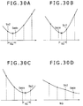
- FIGS. 30A , 30 B, 30 C, and 30 D are diagrams of assistance in explaining an example of a process of calculating a per-block motion vector in an embodiment of the image processing method
- FIG. 31 is a diagram of assistance in explaining processing performance of an example of a process of calculating a per-block motion vector in an embodiment of the image processing method
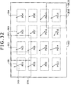
- FIG. 32 is a diagram of assistance in explaining an outline of an embodiment of the image processing method.
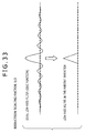
- FIG. 33 is a diagram of assistance in explaining features of the image processing method according to an embodiment by comparison with a existing method
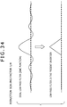
- FIG. 34 is a diagram of assistance in explaining features of the image processing method according to an embodiment by comparison with a existing method
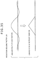
- FIG. 35 is a diagram of assistance in explaining features of the image processing method according to an embodiment by comparison with a existing method
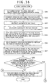
- FIG. 36 is a part of a flowchart of assistance in explaining an example of a process of detecting a translation component and a rotation component of hand movement in a first embodiment of an image processing device;
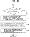
- FIG. 37 is a part of the flowchart of assistance in explaining the example of the process of detecting the translation component and the rotation component of the hand movement in the first embodiment of the image processing device;
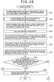
- FIG. 38 is a part of the flowchart of assistance in explaining the example of the process of detecting the translation component and the rotation component of the hand movement in the first embodiment of the image processing device;
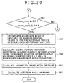
- FIG. 39 is a part of the flowchart of assistance in explaining the example of the process of detecting the translation component and the rotation component of the hand movement in the first embodiment of the image processing device;
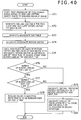
- FIG. 40 is a part of a flowchart of assistance in explaining another example of a process of detecting a translation component and a rotation component of hand movement in the first embodiment of the image processing device;
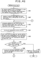
- FIG. 41 is a part of the flowchart of assistance in explaining the other example of the process of detecting the translation component and the rotation component of the hand movement in the first embodiment of the image processing device;
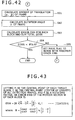
- FIG. 42 is a part of the flowchart of assistance in explaining the other example of the process of detecting the translation component and the rotation component of the hand movement in the first embodiment of the image processing device;
- FIG. 43 is a diagram of assistance in explaining the other example of the process of detecting the translation component and the rotation component of the hand movement in the first embodiment of the image processing device;
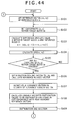
- FIG. 44 is a part of a flowchart of assistance in explaining a first example of a per-block motion vector detecting process in the first embodiment of the image processing device;
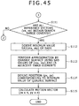
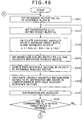
- FIG. 45 is a part of the flowchart of assistance in explaining the first example of the per-block motion vector detecting process in the first embodiment of the image processing device;
- FIG. 46 is a part of a flowchart of assistance in explaining a second example of the per-block motion vector detecting process in the first embodiment of the image processing device;
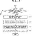
- FIG. 47 is a part of the flowchart of assistance in explaining the second example of the per-block motion vector detecting process in the first embodiment of the image processing device;
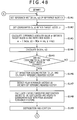
- FIG. 48 is a part of a flowchart of assistance in explaining a third example of the per-block motion vector detecting process in the first embodiment of the image processing device according to the present invention.
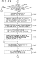
- FIG. 49 is a part of the flowchart of assistance in explaining the third example of the per-block motion vector detecting process in the first embodiment of the image processing device;
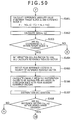
- FIG. 50 is a part of the flowchart of assistance in explaining the third example of the per-block motion vector detecting process in the first embodiment of the image processing device;
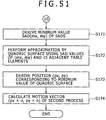
- FIG. 51 is a part of the flowchart of assistance in explaining the third example of the per-block motion vector detecting process in the first embodiment of the image processing device;
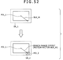
- FIG. 52 is a diagram of assistance in explaining the third example of the per-block motion vector detecting process in the first embodiment of the image processing device
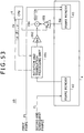
- FIG. 53 is a block diagram showing an example of configuration of a rotation and translation adding unit 19 in the first embodiment of the image processing device
- FIG. 54 is a diagram of assistance in explaining the example of configuration of the rotation and translation adding unit 19 in the first embodiment of the image processing device;
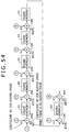
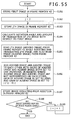
- FIG. 55 is a flowchart of assistance in explaining an example of processing of the rotation and translation adding unit 19 in the first embodiment of the image processing device;
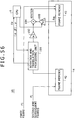
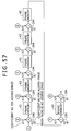
- FIG. 56 is a block diagram showing an example of configuration of the rotation and translation adding unit 19 in the first embodiment of the image processing device
- FIG. 57 is a diagram of assistance in explaining the example of configuration of the rotation and translation adding unit 19 in the first embodiment of the image processing device;
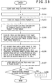
- FIG. 58 is a flowchart of assistance in explaining an example of processing of the rotation and translation adding unit 19 in the first embodiment of the image processing device;
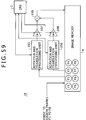
- FIG. 59 is a block diagram showing an example of configuration of the rotation and translation adding unit 19 in the first embodiment of the image processing device;
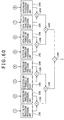
- FIG. 60 is a diagram of assistance in explaining the example of configuration of the rotation and translation adding unit 19 in the first embodiment of the image processing device;
- FIG. 61 is a diagram of assistance in explaining the example of configuration of the rotation and translation adding unit 19 in the first embodiment of the image processing device;
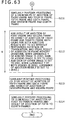
- FIG. 62 is a part of a flowchart of assistance in explaining an example of processing of the rotation and translation adding unit 19 in the first embodiment of the image processing device;
- FIG. 63 is a part of the flowchart of assistance in explaining the example of processing of the rotation and translation adding unit 19 in the first embodiment of the image processing device;
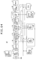
- FIG. 64 is a block diagram showing an example of configuration of a second embodiment of the image processing device.
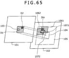
- FIG. 65 is a diagram of assistance in explaining a per-block motion vector detecting process in the second embodiment of the image processing device.
- FIG. 66 is a diagram of assistance in explaining the per-block motion vector detecting process in the second embodiment of the image processing device.
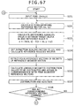
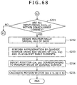
- FIG. 67 is a part of a flowchart of assistance in explaining an example of the per-block motion vector detecting process in the second embodiment of the image processing device;
- FIG. 68 is a part of the flowchart of assistance in explaining the example of the per-block motion vector detecting process in the second embodiment of the image processing device;
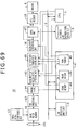
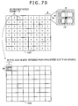
- FIG. 69 is a block diagram showing an example of configuration of a third embodiment of the image processing device.
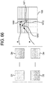
- FIG. 70 is a diagram of assistance in explaining another example of the image processing method.
- FIG. 71 is a diagram of assistance in explaining a process of calculating a motion vector by block matching
- FIG. 72 is a diagram of assistance in explaining the process of calculating the motion vector by block matching
- FIG. 73 is a diagram of assistance in explaining the process of calculating the motion vector by block matching.
- FIG. 74 is a diagram of assistance in explaining the process of calculating the motion vector by block matching.
- Embodiments of an image processing method and an image processing device will hereinafter be described with reference to the drawings by taking examples in which embodiments of an image processing method and an image processing device are applied to an image pickup device and an image pickup method.
- An embodiment, described below, is applied to a hand movement correcting system mainly for still images.
- This embodiment sets an input image frame as a reference frame, and detects a motion vector between the input image frame and an original frame preceding the input image frame, for example an original frame delayed by one frame. Then, hand movement correction for a still image in the present embodiment is performed by superimposing a plurality of images photographed consecutively, for example 3-fps images on each other while making the hand movement correction.
- the present embodiment superimposes a plurality of images taken consecutively while making hand movement correction on the photographed still images, and therefore provides a precision close to a pixel precision (one-pixel precision).
- the present embodiment detects not only translation components in a horizontal direction and a vertical direction between frames as a hand movement motion vector but also a rotation component between the frames, and superimposes the plurality of frames on each other after translation and rotational movement of a frame.
- the embodiment to be described below is not limited to use for still images and is essentially applicable also to moving images.
- moving images because of real time performance, there is an upper limit to the number of frames to be added (number of frames to be superimposed) as later described.
- the embodiment can be applied with identical means to a system generating a moving image resulting from a high degree of noise reduction effect, by using the method of the present embodiment for each frame.
- a plurality of target blocks are set in the original frame, and block matching is performed for each of the plurality of target blocks.
- the present embodiment detects a motion vector for each target block, that is, a per-block motion vector BLK_Vi from each of the created SAD tables TBLi.
- a translation component and a rotation angle of the reference frame with respect to the original frame are calculated from the plurality of per-block motion vectors BLK_Vi, and the reference frame is superimposed on the original frame using the calculated translation component and the calculated rotation angle.
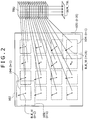
- a first frame is set as a reference, and subsequent frames are superimposed on the first frame as shown in FIG. 3 .
- amounts of translation and rotation angles between the second and subsequent frames to be superimposed and frames immediately preceding the second and subsequent frames to be superimposed are sequentially added up to result in an amount of translation and a rotation angle with respect to the first frame.
- One method of determining an amount of translation and a rotation angle between an original frame and a reference frame using block matching is a method of determining the amount of translation and the rotation angle from a global motion vector of the reference frame as a whole with respect to the original frame. That is, the global motion vector indicates a movement of the frame in question with respect to the preceding frame, and can thus be used as an amount of translation as it is.
- a component in a horizontal direction (x-direction) of the global motion vector is an amount of translation in the horizontal direction
- a component in a vertical direction (y-direction) of the global motion vector is an amount of translation in the vertical direction.
- a relative rotation angle of a global motion vector obtained for a frame of interest this time (reference frame) with respect to a global motion vector obtained for a previous frame is a relative rotation angle of the frame of interest this time with respect to the previous frame.
- a method for calculating the global motion vector in this case, a method can be employed which, as in the case of the existing block matching, makes a majority decision on the basis of per-block motion vectors BLK_Vi detected for 16 target blocks, and calculates, as the global motion vector, the per-block motion vector of a majority decision top (a maximum number of per-block motion vectors that are the same or equal to each other in magnitude and direction).
- this method of calculating the per-block motion vector of the majority decision top as the global motion vector has a problem of detecting a wrong global motion vector (hand movement vector) when a moving image of a subject is taken and the subject during the taking of the moving image is for example a rippling water surface or a tree or grass bending before a wind. Because many of the recent digital cameras pick up and record not only still images but also moving images, the method of calculating the global motion vector by the majority decision system is not desirable in implementation.
- the present embodiment calculates a global motion vector from an aggregate SAD table using aggregate SAD values to be described next.
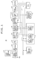
- the present embodiment aggregates SAD values at reference block positions which values correspond to each other within a search range in which each of the SAD tables TBLi is obtained when the 16 SAD tables TBLi for the 16 target blocks created as described above are arranged in a vertical direction so as to be superimposed on each other as shown in FIG. 2 , and thereby obtains aggregate sums of difference absolute values (referred to as aggregate SAD values). Then, an aggregate SAD table SUM_TBL for the plurality of reference block positions within one search range is created as a SAD table including the aggregate SAD values.
- the present embodiment detects a motion vector of the reference picture with respect to the original picture (global motion vector as a hand movement vector in the image pickup device) from the aggregate SAD table SUM_TBL.
- a existing method can be used which detects the position of a minimum value of the aggregate SAD values in the aggregate SAD table SUM_TBL and detects a reference vector corresponding to the detected position of the minimum value of the aggregate SAD values as the global motion vector.
- this method using the aggregate SAD value as the minimum value provides only a motion vector with a precision of a unit of one pixel.
- the present embodiment calculates the global motion vector by performing approximate surface interpolation using the aggregate SAD value at the position of the minimum value of the aggregate SAD values and a plurality of aggregate SAD values in the vicinity of the aggregate SAD value at the position of the minimum value of the aggregate SAD values.
- the global motion vector can be calculated with a precision of less than a unit of one pixel by generating an approximate high-order surface using the aggregate SAD value at the position of the minimum value of the aggregate SAD values and a plurality of aggregate SAD values in the vicinity of the aggregate SAD value at the position of the minimum value of the aggregate SAD values, and detecting the position of a minimal value of the approximate high-order surface.
- a process of the approximate surface interpolation will be described later in detail.
- the aggregate SAD table including the aggregate SAD values is equivalent to a result of en bloc block matching of the entire frame, the global motion vector obtained from the aggregate SAD table is more accurate even in the case of a subject of a moving image as described above that is hard for the majority decision system to deal with.
- the global motion vector obtained at this time is not limited to the aggregate motion vector obtained from the aggregate SAD table; for example, a per-block motion vector of a majority decision top obtained by the majority decision system may be set as global motion vector.
- the aggregate motion vector is desirable for reasons as described above.
- a method of calculating an amount of translation and a rotation angle a method can be employed which determines the amount of translation and the rotation angle of a frame from a plurality of per-block motion vectors calculated for a reference frame, rather than calculating a global motion vector and calculating the amount of translation and the rotation angle using the calculated global motion vector.
- the amount of translation of a frame is in principle obtained as average values of amounts of movement in a horizontal direction and a vertical direction of 16 per-block motion vectors.
- Vxi be a horizontal direction component of a per-block motion vector of a detection frame number i
- Vyi be a vertical direction component of the per-block motion vector of the detection frame number i
- an amount of translation a in the horizontal direction (x-direction) and an amount of translation ⁇ in the vertical direction (y-direction) can be obtained as average values of horizontal direction components and vertical direction components of the 16 per-block motion vectors, as shown in (Equation 4) and (Equation 5) in FIG. 6 .
- the rotation angle ⁇ of a frame can in principle be obtained using the 16 per-block motion vectors as follows.
- detection frame numbers for one reference frame are defined as shown in FIG. 7A .
- the size of one detection frame is 2 a (horizontal direction) by 2 b (vertical direction), as shown in FIG. 7A , where
- a coordinate system is obtained as shown in FIG. 7B , with a center Oc of all the detection frames of the detection frame numbers 0 to 15 as an origin.
- values Pxi and values Pyi corresponding to the detection frame numbers i are defined as shown in FIGS. 7C and 7D .
- the values Pxi and the values Pyi represent weights of distances in the horizontal direction (x-direction) and the vertical direction (y-direction) from the center Oc of all the detection frames to centers of the respective detection frames.
- center coordinates of the detection frame of each detection frame number i can be expressed by (Pxi ⁇ a, Pyi ⁇ b).
- ⁇ F/ ⁇ denotes the partial differentiation of a function F( ⁇ ) with respect to the rotation angle ⁇ .
- the rotation angle ⁇ to be determined of the reference frame can be determined from (Equation 10) shown in FIG. 8(E) .
- the present embodiment calculates an amount of translation and a rotation angle with a higher precision, and superimposes a frame image using the high-precision amount of translation and the high-precision rotation angle.
- the present embodiment determines reliability of a plurality of per-block motion vectors obtained for one reference frame as follows, and calculates an amount of translation and a rotation angle using only per-block motion vectors judged to be highly reliable. The precision of the calculated amount of translation and the calculated rotation angle is thereby improved.
- the present embodiment eliminates as much as possible motion vector components of a moving subject which components are not to be included in the motion vector of a picture as a whole which motion vector results from hand movement, so that the amount of translation and the rotation angle can be calculated with a higher precision.
- the frame in question is not to be used as a frame to be superimposed. Still image processing on the frame in question in the present embodiment is skipped to proceed to processing on a next frame.
- high-precision per-block motion vectors having a precision of less than one pixel as later described are calculated from SAD tables of target blocks corresponding to the calculated highly reliable per-block motion vectors. Then, the calculation of an amount of translation and the detection of a rotation angle as described above are performed using only the calculated high-precision per-block motion vectors.
- the first example and the second example described above can be used in calculating the amount of translation.
- the amount of translation is calculated using high-precision per-block motion vectors obtained for only detection frames of highly reliable detection frame numbers i among the 16 detection frames shown in FIG. 5 .
- the present embodiment excludes, from objects for the calculation of the amount of translation, not only a detection frame of a detection frame number q that is low in reliability but also a per-block motion vector in a detection frame of a detection frame number (15 ⁇ q) at a position symmetrical to the excluded detection frame number q with respect to the point of the center Oc of all the detection frames.
- the amount of translation and the rotation angle of a frame are calculated using only detection frames of high reliability. It can thus be expected that the amount of translation and the rotation angle are calculated with high precision.
- the determination of reliability in a frame unit as described above that is, the determination of reliability of a plurality of per-block motion vectors within a frame is performed as follows.
- an aggregate SAD table SUM_TBL is obtained from 16 SAD tables TBLi according to (Equation 3) mentioned above, and an aggregate motion vector SUM_V (see FIG. 9B ) is obtained from a coordinate position of a minimum SAD value MINs in the aggregate SAD table SUM_TBL.
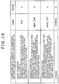
- condition judgment as shown in FIG. 10 is performed for each of the 16 target blocks on the basis of the per-block motion vector BLK_Vi (that is, the coordinate position of the minimum SAD value MINs in the aggregate SAD table SUM_TBL) and the SAD value of each of the 16 target blocks, and labeling and calculation of a score (evaluation score) as shown in FIG. 10 are performed.
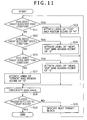
- FIG. 11 is a flowchart representing an example of a process of the labeling and the score calculation. The process of FIG. 11 is for one reference frame, and thus the process of FIG. 11 is repeated for each frame.
- the object target block is given a label of “TOP” and assigned a maximum score value of “4” in this example (step S 12 ).
- step S 13 whether the object target block meets a second condition is determined (step S 13 ).
- the second condition is whether the motion vector BLK_Vi obtained for the object target block and the aggregate motion vector SUM_V are most adjacent vectors on the SAD table though the motion vector BLK_Vi and the aggregate motion vector SUM_V are not identical with each other.
- the second condition is whether the coordinate position of the minimum SAD value MINi in the SAD table TBLi of the object target block and the coordinate position of the minimum SAD value MINs in the aggregate SAD table SUM_TBL are adjacent to each other and differ from each other by one coordinate value in a vertical direction, a horizontal direction, or a diagonal direction.
- the object target block is given a label of “NEXT_TOP” and assigned a score value of “2” in this example (step S 14 ).
- step S 15 When it is determined that the object target block does not meet the second condition, whether the object target block meets a third condition is determined (step S 15 ).
- the third condition is whether in the SAD table of the object target block, a difference between the SAD value (minimum SAD value MINi) at the coordinate position indicated by the per-block motion vector BLK_Vi and a SAD value at a coordinate position corresponding to the coordinate position (coordinate position of the minimum SAD value MINs) indicated by the aggregate motion vector SUM_V on the aggregate SAD table is equal to or smaller than a predetermined threshold value.
- the object target block is given a label of “NEAR_TOP” and assigned a score value of “1” in this example (step S 16 ).
- the object target block is given a label of “OTHERS” and assigned a score value of “0” in this example (step S 17 ).
- step S 18 After completion of the labeling and the score assignment in step S 12 , step S 14 , step S 16 , and step S 17 , the assigned score is cumulatively added to calculate a total score sum_score (step S 18 ).
- step S 19 whether the above process is completed for all of the 16 target blocks within one frame is determined.
- an instruction is given to perform the labeling and the score calculation for a next target block (step S 20 ). Thereafter a return is made to step S 11 to repeat the above-described process.
- the processing routine of the labeling and the score calculation for the 16 target blocks within the one frame is ended.
- the total score sum_score calculated in step S 18 is a total of scores of all the 16 target blocks.
- the flowchart of FIG. 11 is one example; the determination of whether the first condition is met, the determination of whether the second condition is met, and the determination of whether the third condition is met may be made in random order, and any of the determinations may be made first.
- the calculated total score sum_score and a threshold value for reliability are compared with each other. At this time, when the total score sum_score is lower than the threshold value, it can be determined that the motion vectors obtained in the frame in question are of low reliability for detection of a global motion vector.
- the number of per-block motion vectors of target blocks that meet the first condition and the second condition and are thus judged to be of high reliability and given the labels of “TOP” and “NEXT_TOP” is calculated.
- the number is lower than a predetermined threshold value, it can be determined that the motion vectors obtained in the frame in question are of low reliability for detection of a global motion vector.
- the aggregate SAD table is re-generated using only SAD values of SAD tables of the highly reliable target blocks (labeled “TOP” and “NEXT_TOP”) satisfying the first condition and the second condition.
- the aggregate motion vector as global motion vector is recalculated on the basis of the re-generated aggregate SAD table.
- the amount of translation and the rotation angle of the frame can be calculated from the recalculated aggregate motion vector.
- the global motion vector obtained at this time is not limited to the aggregate motion vector obtained from the aggregate SAD table, and may be obtained by making a majority decision on the basis of highly reliable per-block motion vectors, for example.
- the amount of translation ( ⁇ , ⁇ ) and the rotation angle ⁇ can be determined using only per-block motion vectors having the label of “TOP” and the label of “NEXT_TOP” indicating high reliability on the basis of (Equation 4) to (Equation 10) described with reference to FIGS. 6 to 8E .
- the present embodiment employs a method of calculating the amount of translation ( ⁇ , ⁇ ) and the rotation angle ⁇ using only per-block motion vectors having the label of “TOP” and the label of “NEXT_TOP” indicating high reliability.
- the present embodiment performs the following process.
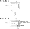
- the present embodiment gradually narrows down a search range for each target block, and performs the block matching process (block matching for the whole of a reference frame will hereinafter be referred to as detection) in a plurality of stages.
- block matching detection is performed in two stages.
- a search range SR_ 1 for each target block TGi in a first detection is set to a maximum, and a plurality of per-block motion vectors BLK_Vi as described above are obtained.
- the plurality of per-block motion vectors are evaluated, and a search is made for per-block motion vectors having high evaluation values.
- Equation 4 and (Equation 5) described above are performed using only the per-block motion vectors having the high evaluation values to obtain an amount of translation ( ⁇ , ⁇ ) of the first detection.
- a search range for each target block in a second detection is determined from the amount of translation of the first detection.
- a global motion vector (hand movement vector) may be calculated from blocks having high evaluation values, so that the amount of translation of the first detection is calculated from the global motion vector and then the search range for each target block in the second detection is determined from the amount of translation of the first detection.
- a search range narrower than the search range in the first detection with the block range in which there is correlation between the reference frame and the original frame as a center as shown in FIG. 12B can be set as a search range SR_ 2 for each target block in the second detection process.
- a positional displacement (search range offset) between a central position Poi_ 1 of the search range SR_ 1 in the first detection and a central position Poi_ 2 of the search range SR_ 2 in the second detection corresponds to the amount of translation (corresponding to the global motion vector) detected in the first detection.
- the detection process using the narrowed search range SR_ 2 for each target block provides a result of block matching with a higher precision than in the first-stage detection process as a result of the second detection.
- the present embodiment calculates the amount of translation and the rotation angle of the frame as described above using per-block motion vectors having high evaluation values among per-block motion vectors obtained in the second detection. Thereby the amount of translation and the rotation angle can be obtained with a high precision.
- the aggregate SAD table used in the present embodiment is substantially equivalent to a result of en bloc block matching of the entire frame rather than the SAD table for each block.
- motion vectors surviving after the majority decision described in the existing art that is, the motion vector of a majority decision top and the aggregate motion vector obtained from the aggregate SAD table are equal to each other.
- a result of majority decision is a near-random motion vector of low reliability.
- the aggregate motion vector is derived as a result relatively close to a correct solution.
- the present embodiment is characterized by realizing a stable hand movement correction system that provides a more natural image under a policy of attaching importance to a frame as a whole and excluding an unreliable frame from frames to be superimposed on each other.
- one method of the present embodiment makes a majority decision on the basis of per-block motion vectors BLK_Vi detected for 16 target blocks, and calculates the motion vector of a majority decision top (a maximum number of per-block motion vectors that are the same or equal to each other in magnitude and direction).
- labeling and score assignment as shown in FIG. 10 are performed on the basis of the per-block motion vectors BLK_Vi detected for the 16 target blocks and the SAD values of the respective per-block motion vectors BLK_Vi.
- the first condition is whether a per-block motion vector BLK_Vi obtained for an object target block for which labeling and score calculation are to be performed and the motion vector of the majority decision top are equal to each other. That is, whether the coordinate position of a minimum SAD value MINi in a SAD table TBLi of the object target block is equal to the coordinate position of the motion vector of the majority decision top is determined.
- the second condition is whether the motion vector BLK_Vi obtained for the object target block and the motion vector of the majority decision top are most adjacent vectors on the SAD table though the motion vector BLK_Vi and the motion vector of the majority decision top are not identical with each other. Specifically, the second condition is whether the coordinate position of the minimum SAD value MINi in the SAD table TBLi of the object target block and the coordinate position corresponding to the motion vector of the majority decision top are adjacent to each other and differ from each other by one coordinate value in a vertical direction, a horizontal direction, or a diagonal direction.
- the third condition is whether in the SAD table of the object target block, a difference between the SAD value (minimum SAD value MINi) at the coordinate position indicated by the per-block motion vector BLK_Vi and a SAD value at the coordinate position on the SAD table which position corresponds to the motion vector of the majority decision top is equal to or smaller than a predetermined threshold value.
- the labeling and the score assignment with the motion vector of the majority decision top as a reference are performed for the motion vectors of the 16 target blocks for one frame. Then, a total score many_score of assigned scores is calculated.
- the present embodiment determines that the motion vectors obtained for the frame in question are of high reliability when a difference between the coordinate position of the minimum SAD value corresponding to the aggregate motion vector SUM_V and the coordinate position of the SAD value corresponding to the motion vector of the majority decision top is within a predetermined value, for example when the difference is within one adjacent pixel, when the total score sum_score is equal to or higher than a predetermined threshold value, and when the total score many_score is equal to or higher than a predetermined threshold value.
- a re-aggregate SAD table RSUM_TBL is generated using only SAD values of SAD tables of target blocks given the labels of “TOP” and “NEXT_TOP” among the labels of target blocks labeled with the aggregate motion vector as a reference in this example.
- a global motion vector (aggregate motion vector) is calculated by applying approximate surface interpolation to a minimum SAD value and SAD values at coordinate positions adjacent to the minimum SAD value in the re-aggregate SAD table RSUM_TBL. Then, using the calculated aggregate motion vector, a search range at the time of second detection is determined, or the amount of translation and the rotation angle are calculated.
- the amount of translation is calculated, and the search range at the time of the second detection is determined, or calculation based on the above-described (Equation 4) to (Equation 10) is performed, and the amount of translation and the rotation angle are calculated.
- the existingly proposed method of predicting a motion vector (global motion vector) from frequency of the motion vector in a time axis direction and the method according to the embodiment of the present invention described above may be combined with each other to further improve reliability and precision.
- the present embodiment generates a SAD table and calculates a per-block motion vector for each of a plurality of target blocks within one frame.
- the present embodiment is to be applied to an image pickup device using an image pickup element currently having over five million pixels, it is difficult to realize the present embodiment on a practical circuit scale because the scale of the SAD table is increased in proportion to the number of pixels of one picture.
- Patent Document 3 Japanese Patent Laid-Open No. 2005-38396.
- a device disclosed in Patent Document 3 includes means for obtaining a motion vector in a size resulting from reducing conversion of an image and means for sharing an identical SAD table between a plurality of blocks.
- the reducing conversion of an image and the sharing of an identical SAD table between a plurality of blocks are a very good method for realizing reduction of SAD table size, and are used in other fields for motion vector detection and scene change detection in an MPEG (Moving Picture Experts Group) image compression system, for example.
- MPEG Motion Picture Experts Group
- Patent Document 3 has problems in that the reducing conversion of an image and memory (DRAM (Dynamic RAM (Random Access Memory))) access at the time of the reducing conversion consume time and memory space, and because the plurality of blocks make time-division access to the SAD table, memory access is greatly increased and this process also takes time. Real-time performance and reduction of a system delay time are both required in hand movement correction for moving images, and therefore the process time becomes a problem.
- DRAM Dynamic RAM (Random Access Memory)
- a result of evaluation on a large number of people indicates that a range of hand movement in the case of a still image of three frames/second (3 fps), for example, is about ⁇ 10% with an entire frame as 100.
- a SAD table size required with the currently proposed technology used as it is about 80 megabits.
- a memory storing information of the SAD table needs to be a built-in SRAM (Static RAM (Random Access Memory)). Even though semiconductor process rules have progressed, this size is about three digits apart from a practical level.
- the reducing conversion of an image requires a low-pass filter for removing aliasing (folding distortion) and low illuminance noise to be implemented as preprocessing for the reduction process.
- characteristics of the low-pass filter are changed according to a reduction scaling factor, and especially when a low-pass filter in a vertical direction is a multiple-tap digital filter, many line memories and operation logics are required, thus presenting a problem of an increase in circuit scale.
- the present embodiment uses a method and a device for image processing which can greatly reduce SAD table size when a global motion vector between two frames is calculated using block matching.
- the present embodiment reduces the reference vector, distributes and adds the SAD value to a plurality of reference vectors corresponding to the reduced reference vector and adjoining the reference reduced vector, and thus stores the SAD value.
- the present embodiment greatly reduces the size of the SAD table as compared with the existing SAD table, and solves the two problems of an increase in processing time and consumption of memory space that are involved in the reducing conversion of an image and a circuit increase involved in implementing an appropriate low-pass filter for avoiding aliasing attendant on the reducing conversion of an image.
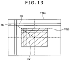
- FIGS. 13 to 15 are diagrams of assistance in explaining an outline of a new block matching method used in the present embodiment.
- FIG. 13 shows a relation between a existing SAD table TBLo and a reduced SAD table TBLs generated in the image processing method of the present embodiment.
- a plurality of search ranges are set in a reference frame with the positions of a plurality of target blocks set in an original frame, or 16 target blocks in this example, as respective centers. Then, a plurality of reference blocks as described above are set in each of the plurality of search ranges, and a sum of absolute values of differences between luminance values of pixels within each reference block and luminance values of corresponding pixels within the target block, that is, a SAD value is obtained.
- the obtained SAD value is written in the SAD table TBLo as a table element tbl at an address corresponding to a reference vector RV of the reference block in question.
- a reference vector RV representing a positional displacement in the frame image between a target block and a reference block and the SAD value of the reference block as each table element of the SAD table TBLo are in one-to-one correspondence with each other. That is, the existing SAD table TBLo has a number of table elements of SAD values which number is equal to the number of reference vectors RV that can be obtained in a search range.
- the reference vector RV of the reference block in question is reduced at a reduction ratio of 1/n (n is a natural number) into a reference reduced vector CV.
- a horizontal direction reduction scaling factor and a vertical direction reduction scaling factor are the same for convenience of the description.
- the horizontal direction reduction scaling factor and the vertical direction reduction scaling factor may be different values independent of each other.
- the horizontal direction reduction scaling factor and the vertical direction reduction scaling factor set as one divided by an arbitrary natural number independently of each other are more flexible and convenient.
- the position of a target block as center of a search range is set as a reference position (0, 0)
- reference vectors indicate displacements (vx, vy) (vx and vy are integers) in the horizontal direction and the vertical direction in pixel units from the reference position
- each of the reference vectors RV is expressed as a reference vector (vx, vy).
- a position (vx/n, vy/n) indicated by a reference reduced vector (vx/n, vy/n) obtained by reducing a reference vector (vx, vy) to 1/n in each of the horizontal direction and the vertical direction may not be an integer and may include a decimal component. Therefore, in the present embodiment, when a SAD value obtained in correspondence with the original reference vector RV before the reduction is stored as a table element corresponding to one reference vector closest to the reference reduced vector CV, an error occurs.
- a plurality of positions (table elements) indicated by a plurality of reference vectors in the vicinity of the position (vx/n, vy/n) indicated by the reference reduced vector CV are detected first. Then, the SAD value obtained for the reference block of the reference vector RV is distributed and added to SAD values corresponding to the plurality of adjacent reference vectors indicating the detected positions.
- the SAD values to be distributed and added in correspondence with the adjacent reference vectors are calculated from the SAD value obtained in correspondence with the original reference vector RV before the reduction, using a relation between the positions indicated by the reference reduced vector and each of the adjacent reference vectors.
- Each of the calculated SAD values is added as a table element component of the corresponding reference vector.
- not only distributing but also adding the SAD values means that the plurality of reference vectors adjacent to the reference reduced vector are detected repeatedly for a plurality of different reference reduced vectors and thus a plurality of SAD values are added together for one reference vector.
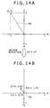
- the position indicated by the reference reduced vector CV includes decimal components, and does not match a position indicated by a reference vector.
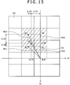
- a plurality of adjacent reference vectors indicating positions adjacent to the position indicated by the reference reduced vector CV are detected, as shown in FIG. 15 .
- four adjacent reference vectors NV 1 , NV 2 , NV 3 , and NV 4 are detected for the one reference reduced vector CV.
- a SAD value obtained for the reference block of the reference vector RV is distributed and added as SAD values corresponding to the four adjacent reference vectors NV 1 , NV 2 , NV 3 , and NV 4 .
- the SAD values to be distributed and added to the four adjacent reference vectors NV 1 , NV 2 , NV 3 , and NV 4 are calculated as linearly weighted distribution values using positional relations between a position P 0 (shown as a cross mark in FIG. 15 ) indicated by the reference reduced vector CV and positions P 1 , P 2 , P 3 , and P 4 (shown as circle marks in FIG. 15 ) indicated by the four adjacent reference vectors NV 1 , NV 2 , NV 3 , and NV 4 , respectively.
- the position P 0 indicated by the reference reduced vector CV in the example of FIG. 15 internally divides line segments defined by the positions P 1 , P 2 , P 3 , and P 4 indicated by the four adjacent reference vectors NV 1 , NV 2 , NV 3 , and NV 4 , respectively, around the position P 0 at 1:3 in the horizontal direction and at 3:1 in the vertical direction.
- S ⁇ be the SAD value obtained in correspondence with the reference vector RV before the reduction
- the obtained values SADp 1 , SADp 2 , SADp 3 , and SADp 4 are added to the SAD table elements corresponding to the positions P 1 , P 2 , P 3 , and P 4 indicated by the four adjacent reference vectors NV 1 , NV 2 , NV 3 , and NV 4 , respectively.
- the above process is performed for all reference blocks within a search range.
- the reduced SAD table TBLs obtained by reducing the SAD table TBLo of existing size which table has one-to-one correspondence with all reference vectors to 1/n in the horizontal direction and 1/n in the vertical direction, and determine the SAD values corresponding to the reference vectors adjacent to the reference vector RV as table elements in the reduced SAD table TBLs (see FIG. 13 ).
- the number of table elements of the reduced SAD table TBLs in the present embodiment is 1/n 2 of the number of table elements of the existing SAD table TBLo, so that table size can be greatly reduced.
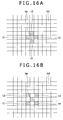
- the four reference vectors adjacent to the reference reduced vector CV are detected, and the SAD values calculated for the reference block in question (reference vector RV) are added as linearly weighted distribution values to the SAD table elements corresponding to the four adjacent reference vectors.
- a method for selecting a plurality of reference vectors adjacent to the reference reduced vector CV and a method of the distribution and addition to the SAD table elements corresponding to the adjacent reference vectors are not limited to the above-described example.
- the reference block is moved to all positions within the search range, and the SAD values of all the reference blocks are assigned to the SAD table (reduced SAD table in the present embodiment).
- detection of a motion vector is completed when a SAD table completed as described above is searched for a table element having a minimum SAD value and the table address of the table element having the minimum value is converted to a reference vector.
- the SAD table in the method according to the present embodiment is a reduced SAD table corresponding to reduced reference vectors obtained by reducing reference vectors, and therefore a minimum value in the reduced SAD table does not correspond as it is to an accurate motion vector.
- a device that tolerates errors to a certain degree may calculate a motion vector by converting the table address of the table element having the minimum value in the reduced SAD table to a reference vector and multiplying the reference vector by a reciprocal of the reduction ratio of 1/n, that is, by n.
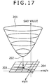
- the accurate motion vector (per-block motion vector) is detected with the precision of the original vector by performing interpolation processing on table element values of the reduced SAD table as described below.
- SAD tables are obtained for a plurality of target blocks using the method of block matching utilizing existing reference vectors rather than reduced reference vectors
- an aggregate SAD table is obtained by aggregating SAD values at corresponding coordinate positions in the plurality of obtained SAD tables
- a global motion vector is calculated by subjecting the aggregate SAD table to approximate surface interpolation.
- An interpolation process to be described below can also be used as the approximate surface interpolation in this case.
- a first example of an interpolation process for calculating a more accurate motion vector is a method of approximating a plurality of SAD table element values (SAD values) in a reduced SAD table by one quadric surface.
- a table element having a minimum SAD value integer precision minimum value table element (integer precision table address)
- a plurality of integer precision table elements around the center of the integer precision minimum value table element are obtained in the reduced SAD table.
- the quadric surface of SAD values is determined by a method of least squares.
- a minimum SAD value of the quadric surface is detected.
- a position corresponding to the detected minimum SAD value (a position shifted from the reference position in the reference frame) is detected.
- the detected position is set as a decimal precision minimum value table address (corresponding to a vector (minimum value vector) indicating the minimum SAD value in the reduced SAD table).
- to set a unique quadric surface requires at least an integer precision minimum value table element tm and four integer precision table elements t 1 , t 2 , t 3 , and t 4 adjacent to the table element tm, the four integer precision table elements t 1 , t 2 , t 3 , and t 4 being at positions such that the table element tm is sandwiched from both sides between the integer precision table elements, as shown in FIG. 16A or 16 B.
- a SAD value axis is considered as an axis perpendicular to the axis vx/n and the axis vy/n, and a coordinate space formed by the three axes is assumed.
- a quadric curve is generated in the coordinate space in FIG. 17 from the SAD value of the integer precision minimum value table element tm and the SAD values of the two table elements t 1 and t 3 between which the integer precision minimum value table element tm is interposed.
- Another quadric curve is generated in the coordinate space in FIG. 17 from the SAD value of the integer precision minimum value table element tm and the SAD values of the other two table elements t 2 and t 4 between which the minimum value table element tm is interposed.
- a quadric surface 201 including the two quadric curves is obtained by a method of least squares. The quadric surface 201 is generated in the coordinate space as shown in FIG. 17 .
- a minimum value 202 of the generated quadric surface 201 of SAD values is detected.
- a position (vx/n, vy/n) corresponding to the minimum SAD value (a position 203 in FIG. 17 ) is detected.
- the detected position (vx/n, vy/n) is detected as a decimal precision table element (table address).
- a vector (minimum value vector) 204 corresponding to the detected decimal precision table element is multiplied by n as shown in FIG. 18 , whereby a motion vector 205 with an original magnitude precision is obtained.
- the motion vector 205 is ( ⁇ 3.108, ⁇ 5.968), which is obtained by multiplying ( ⁇ 0.777, ⁇ 1.492) by four.
- This motion vector 205 is a reproduction of a motion vector on the scale of an original image.
- table elements in a wide range invites an increase in an amount of calculation and increases a possibility of using the false value of a local minimum dependent on an image pattern. Therefore table elements in a rectangular region of an appropriate number of adjacent table elements are used.
- FIGS. 20A and 20B represent an example of using table elements in a rectangular region (filled in FIG. 20A ) of 3 (horizontal direction) ⁇ 3 (vertical direction) table elements around the center of the integer precision minimum value table element tm.
- a quadric surface 201 as shown in FIG. 20B is generated by the method of least squares, using the SAD values of the integer precision minimum value table element tm and eight adjacent table elements adjacent to the integer precision minimum value table element tm as shown in FIG. 20A . Then, a minimum value 202 of the generated quadric surface 201 of SAD values is detected. A position (vx/n, vy/n) corresponding to the minimum SAD value (a position 203 in FIG. 20B ) is detected. The detected position 203 is detected as the position of a decimal precision minimum value table element (decimal precision minimum value table address).
- a vector (minimum value vector) 204 corresponding to the detected position 203 of the decimal precision table element is multiplied by n as shown in FIG. 18 , whereby a motion vector 205 with an original magnitude precision is obtained.
- a method of calculating the position 203 corresponding to the minimum value 202 of the SAD value quadric surface 201 is as follows. As shown in FIG. 21 , (x, y) coordinates with the position of the integer precision minimum value table element tm as an origin (0, 0) are considered.
- the SAD value of each table element in a table of FIG. 21 is Sxy.
- the SAD value of the integer precision minimum value table element tm (position (0, 0)) is expressed as S 00
- the SAD value of a table element at a lower right position (1, 1) is expressed as S 11 .
- the decimal precision position (dx, dy) is thus obtained with the position of the integer precision minimum value table element tm as origin (0, 0). Therefore the position 203 with respect to the central position of the search range can be detected from the decimal precision position (dx, dy) and the position of the integer precision minimum value table element tm.
- FIGS. 23A and 23B represent an example of using table elements in a rectangular region (filled in FIG. 23A ) of 4 (horizontal direction) ⁇ 4 (vertical direction) table elements with the integer precision minimum value table element tm substantially at a center.
- the SAD values of a left adjacent table element and a right adjacent table element in the horizontal direction as viewed from the integer precision minimum value table element tm are compared with each other.
- a table element adjacent to the adjacent table element having a lower value in a direction of the adjacent table element having the lower value is employed as an adjacent table element in a fourth column.
- the SAD values of an upper adjacent table element and a lower adjacent table element in the vertical direction as viewed from the integer precision minimum value table element tm are compared with each other.
- a table element adjacent to the adjacent table element having a lower value in a direction of the adjacent table element having the lower value is employed as an adjacent table element in a fourth row.
- the SAD values of a left adjacent table element and a right adjacent table element in the horizontal direction of the integer precision minimum value table element tm are “177” and “173”. Therefore a column adjacent on the right side to the right adjacent table element having the lower SAD value of “173” is employed as the fourth column.
- the SAD values of an upper adjacent table element and a lower adjacent table element in the vertical direction of the integer precision minimum value table element tm are “168” and “182”. Therefore a row adjacent on the upper side to the upper adjacent table element having the lower SAD value of “168” is employed as the fourth row.
- a quadric surface 201 is generated by the method of least squares, using the SAD values of the integer precision minimum value table element tm and the 15 adjacent table elements adjacent to the integer precision minimum value table element tm. Then, a minimum value 202 of the generated quadric surface 201 of SAD values is detected. A position (vx/n, vy/n) corresponding to the minimum SAD value (position 203 in FIG. 23B ) is detected. The detected position 203 is detected as the position of a decimal precision minimum value table element (decimal precision minimum value table address).
- a vector (minimum value vector) 204 corresponding to the detected position 203 of the decimal precision table element is multiplied by n as shown in FIG. 18 described above, whereby a motion vector 205 with an original magnitude precision is obtained.
- a method of calculating the position 203 corresponding to the minimum value 202 of the SAD value quadric surface 201 in this example is as follows. As shown in FIGS. 24A , 24 B, 24 C, and 24 D, (x, y) coordinates with the position of the integer precision minimum value table element tm as an origin (0, 0) are considered.
- FIGS. 24A , 24 B, 24 C, and 24 D need to be considered according to the position of the integer precision minimum value table element tm in a rectangular region of 16 table elements.
- the SAD value of each table element in tables of FIGS. 24A , 24 B, 24 C, and 24 D is Sxy.
- the SAD value of the integer precision minimum value table element tm (position (0, 0)) is expressed as S 00
- the SAD value of a table element at a position (1, 1) is expressed as S 11 .
- Kx and Ky in (Equation C) and (Equation D) of FIG. 25 are values corresponding to the four table element arrangements shown in FIGS. 24A , 24 B, 24 C, and 24 D when (Kx, Ky) coordinates are considered with a central position in a rectangular region of the integer precision minimum value table element tm and 15 table elements surrounding the integer precision minimum value table element tm as an origin (0, 0), as shown in FIG. 26 .
- ⁇ x and ⁇ y in (Equation C) and (Equation D) shown in FIG. 25 represent amounts of displacement of (Kx, Ky) coordinates with respect to (x, y) coordinates in each of the table element arrangements of FIGS. 24A , 24 B, 24 C, and 24 D.
- FIG. 26 As is understood from FIG. 26 ,
- the decimal precision position (dx, dy) is thus obtained with the position of the integer precision minimum value table element tm as origin (0, 0). Therefore the position 203 with respect to the central position of the search range can be detected from the decimal precision position (dx, dy) and the position of the integer precision minimum value table element tm.
- a second example of an interpolation process for calculating a more accurate motion vector generates a cubic curve in a horizontal direction using the SAD values of a plurality of table elements in the horizontal direction including an integer precision minimum value table element in a reduced SAD table and generates a cubic curve in a vertical direction using the SAD values of a plurality of table elements in the vertical direction including the integer precision minimum value table element, detects a position (vx, vy) of a minimal value of each of the cubic curves, and sets the detected position as a decimal precision minimum value address.
- FIGS. 27A and 27B are diagrams of assistance in explaining the second example.
- a SAD value axis is considered as an axis perpendicular to the axis vx/n and the axis vy/n, and a coordinate space formed by the three axes is assumed.
- a cubic curve 206 in the horizontal direction is generated in the coordinate space using the SAD values of four table elements in the horizontal direction including the integer precision minimum value table element tm among the 16 table elements, the 16 table elements being the integer precision minimum value table element tm and the table elements surrounding the integer precision minimum value table element tm.
- a horizontal direction position of a decimal precision minimum value table element position is detected as a horizontal direction position vx/n corresponding to a minimal value of the cubic curve 206 in the horizontal direction.
- a cubic curve 207 in the vertical direction is generated in the coordinate space using the SAD values of four table elements in the vertical direction including the integer precision minimum value table element tm among the 16 table elements, the 16 table elements being the integer precision minimum value table element tm and the table elements surrounding the integer precision minimum value table element tm.
- a vertical direction position of the decimal precision minimum value table element position is detected as a vertical direction position vy/n corresponding to a minimal value of the cubic curve 207 in the vertical direction.
- the decimal precision minimum value table element position (decimal precision minimum value table address) 208 is detected from the horizontal direction position and the vertical direction position obtained by the above process of the decimal precision minimum value table element position. Then, a vector (minimum value vector) 209 corresponding to the detected decimal precision table element position 208 is multiplied by n as shown in FIG. 18 described above, whereby a motion vector with an original magnitude precision is obtained.
- the second example is a method of determining four table elements in each of the horizontal direction and the vertical direction by the method described in the first example and uniquely determining the cubic curve in each of the horizontal direction and the vertical direction as shown in FIG. 27B .
- a method of calculating the position 208 corresponding to the minimum value 202 of the SAD value cubic curves 206 and 207 is as follows. Letting SAD values at four points in the vicinity of the minimum value of the cubic curve in one of the horizontal direction and the vertical direction be S 0 , S 1 , S 2 , and S 3 in order along one of the horizontal direction and the vertical direction, an equation for calculating a decimal component u to obtain the minimum value differs depending on which of three sections Ra, Rb, and Rc shown in FIG. 28 includes the decimal precision minimum value.
- the section Ra is an interval between the position of the SAD value S 0 and the position of the SAD value S 1 .
- the section Rb is an interval between the position of the SAD value S 1 and the position of the SAD value S 2 .
- the section Rc is an interval between the position of the SAD value S 2 and the position of the SAD value S 3 .
- FIGS. 30A , 30 B, 30 C, and 30 D are diagrams of assistance in explaining the determination. As shown in FIGS. 30A , 30 B, and 30 C, first, a minimum value Smin of integer precision SAD values and a second lowest integer precision SAD value Sn 2 are detected, and the decimal precision minimum value is detected as value occurring between the position of the detected minimum value Smin of the integer precision SAD values and the position of the second lowest integer precision SAD value Sn 2 .
- a motion vector on an original image scale can be calculated using the reduced SAD table of small size which table is scaled down to 1/n 2 .
- FIG. 31 shows that a vector detection result substantially similar to a existing result is obtained in this case even though the reduced SAD table of small size which table is scaled down to 1/n 2 is used.
- An axis of abscissas in FIG. 31 indicates a reduction scaling factor n in a direction of one dimension as one of the horizontal direction and the vertical direction.
- An axis of ordinates indicates an error (vector error) of a detected motion vector.
- the numerical value of a vector error in FIG. 31 is expressed as a number of pixels.
- a curve 301 represents average values of vector errors with respect to the reduction scaling factor.
- a curve 302 represents values (3 ⁇ (99.7%)) three times variances ⁇ of vector errors with respect to the reduction scaling factor.
- a curve 303 is an approximate curve approximate to the curve 302 .
- FIG. 31 shows vector errors with respect to the reduction scaling factor n in the direction of one dimension. Because the SAD table is a two-dimensional table, the size of the table (number of table elements) is reduced at a rate of the square of the reduction scaling factor. On the other hand, the vector error increases only substantially linearly. Thus the usefulness of the method according to the present embodiment can be understood.
- the present embodiment divides the reference frame 102 into a plurality of regions, or 16 regions in this example, and detects a motion vector (per-block motion vector) 205 in each of the divided regions. This is because, as described above, there is a strong possibility of a moving subject being included in a frame, so that 16 motion vectors 205 are detected within one reference frame 102 as in FIG. 32 , for example, and are statistically processed while changes from such motion vectors 205 in past frames are taken into consideration, whereby one global motion vector for one frame, that is, a hand movement vector of the frame can be determined.
- search ranges SR 1 , SR 2 , . . . , and SR 16 having reference positions P 0 to PO 16 of the 16 motion vectors 205 desired to be detected as respective centers of the search ranges SR 1 , SR 2 , . . . , and SR 16 are set, and projected image blocks IB 1 , IB 2 , . . . , and IB 16 of target blocks are assumed in the respective search ranges.
- a SAD table TBLi has the configuration of a reduced SAD table.
- the 16 reduced SAD tables obtained for the target blocks in the 16 search ranges are arranged so as to be stacked, as shown in FIG. 2 .
- the SAD values at reference block positions corresponding to each other within the search ranges, that is, same coordinate positions in the reduced SAD tables are aggregated to obtain aggregate SAD values.
- an aggregate reduced SAD table for a plurality of reference block positions within one search range is generated as a SAD table including the aggregate SAD values.
- an aggregate SAD table SUM_TBL has the configuration of the aggregate reduced SAD table.
- the image processing method using the reduced SAD tables according to the present embodiment described above has the following two features that differ greatly as compared with the method of calculating a motion vector in a size resulting from the reducing conversion of an image as described in Patent Document 3, which has been described as a existing method.
- the method according to the present embodiment does not require a process of reducing conversion of an image at all, unlike the existing method described in Patent Document 3.
- a SAD value calculated for a reference block is assigned and added to a SAD table (reduced SAD table)
- an address conversion corresponding to a reduction scaling factor is performed at the same time.
- the method according to the present embodiment has the feature of eliminating the need for a logic for the reducing conversion of an image as in the existing method described in Patent Document 3, a time and bandwidth consumption for storing a reduced image in a memory, and securing of an area in the memory where the reduced image is to be pasted.
- the characteristic of an ideal low-pass filter in the reducing conversion is a function similar to a sinc function.
- the sinc function itself is an infinite tap FIR (Finite Impulse Response) filter with a cutoff frequency of f/2, which filter is expressed as sin(x ⁇ )/(x ⁇ ).
- a low-pass filter with an ideal cutoff frequency of f/(2n) at a reduction scaling factor 1/n is expressed as sin(x ⁇ /n)/(x ⁇ /n).
- this may be regarded as one form of the sinc function.
- FIGS. 33 to 35 Forms of the sinc function (ideal characteristics of a low-pass filter) when the reduction scaling factor is 1 ⁇ 2, 1 ⁇ 4, and 1 ⁇ 8 are shown on upper sides of FIGS. 33 to 35 , respectively. It is clear from FIGS. 33 to 35 that the function is expanded in a direction of a tap axis as the reduction scaling factor is increased. That is, it can be said that the number of taps of the FIR filter needs to be increased even when the infinite tap sinc function is approximated by only main coefficients.
- the method of calculating the motion vector using the reduced image as the existing method described in Patent Document 3 also involves a trade-off in that although the higher the image reduction scaling factor, the greater the SAD table reducing effect of the method, the higher the reduction scaling factor, the higher the cost of the low-pass filter as a filter for preprocessing in generating an image.
- Images of a low-pass filter in the method according to the present embodiment are shown on lower sides of FIGS. 33 to 35 .
- the method according to the present embodiment does not involve an image reduction process.
- the images of the low-pass filter in a process of reduced SAD table generation and operation are shown in FIGS. 33 to 35 .
- characteristics of the low-pass filter are simple filter characteristics in which a main coefficient part of the sinc function is approximated linearly
- the number of taps is increased in such a manner as to be interlocked with the reduction scaling factor.
- This is suitable to the fact that the number of taps has a more dominant effect on performance of the low-pass filter as the cutoff frequency is lowered, as described above. That is, the process itself of distributing and adding SAD values in the present embodiment such for example as the process of performing linearly weighted distribution and addition according to the embodiment is equivalent to implementing a high-performance low-pass filter interlocked with the scaling factor with simple circuitry.
- Patent Document 3 reduces an image by passing the image through a low-pass filter and re-sampling the image. At this time, a considerable amount of image information is lost. That is, in the operation of the low-pass filter, the word length of a luminance value of image information is greatly rounded and then stored in a memory, and less significant bits of most of image information do not have effect on an image after reduction.
- the method according to the present embodiment calculates SAD values using all bit information of luminance values of all pixels equally, determines distribution and addition values of the SAD values, and adds the distribution and addition values to a reduced SAD table. If only the word length of each table element value in the reduced SAD table is increased, calculation can be performed with no rounding error included all the way to the output of final SAD values. Because the area of the reduced SAD table is smaller than that of a frame memory, increasing the word length of the reduced SAD table does not present a great problem. As a result, the reduced SAD table and motion vector detection can be realized with a high precision.
- FIG. 1 is a block diagram showing an example of the image pickup device as the embodiment of the image processing device.
- the present invention is applied to a hand movement correction system for still images.
- the present embodiment is not limited to use for still images, and is essentially applicable to moving images.
- moving images because of real time performance, there is an upper limit to the number of frames to be added together.
- the embodiment can be applied with identical means to a system generating a moving image resulting from a high degree of noise reduction effect, by using the present method for each frame.
- the first embodiment sets an input image frame as a reference frame, and detects a motion vector between the input image frame and an image frame obtained by delaying an input image frame in a frame memory by one frame. Then, hand movement correction for a still image in the first embodiment is performed by superimposing a plurality of images photographed consecutively, for example 3-fps images on each other while making the hand movement correction.
- the first embodiment superimposes a plurality of images taken consecutively while making the hand movement correction on the photographed still images, and therefore provides a precision close to a pixel precision (one-pixel precision).
- the first embodiment detects not only translation components in a horizontal direction and a vertical direction between frames as a hand movement motion vector but also a rotation component between the frames.
- the image pickup device is formed by connecting a CPU (Central Processing Unit) 1 to a system bus 2 and connecting an image pickup signal processing system 10 , a user operation input unit 3 , an image memory unit 4 , a recording and reproduction device unit 5 and the like to the system bus 2 .
- the CPU 1 includes a ROM (Read Only Memory) for storing a program for performing various software processes, a RAM (Random Access Memory) for a work area, and the like.
- the image pickup device in the example of FIG. 1 In response to an image pickup recording start operation via the user operation input unit 3 , the image pickup device in the example of FIG. 1 records picked-up image data as later described. In addition, in response to an operation for starting reproduction of a picked-up and recorded image which operation is performed via the user operation input unit 3 , the image pickup device in the example of FIG. 1 reproduces the picked-up image data recorded on a recording medium of the recording and reproduction device unit 5 .
- an image pickup element 11 is irradiated with incident light from a subject via a camera optical system (not shown) having an image pickup lens 10 L, whereby image pickup is performed.
- the image pickup element 11 is formed by a CCD (Charge Coupled Device) imager.
- the image pickup element 11 may be formed by a CMOS (Complementary Metal Oxide Semiconductor) imager.
- the output analog image pickup signal is supplied to a preprocessing unit 13 to be subjected to preprocessing such as defect correction, ⁇ correction and the like, and then the result is supplied to a data converting unit 14 .
- the data converting unit 14 converts the analog image pickup signal input to the data converting unit 14 into a digital image pickup signal (YC data) including a luminance signal component Y and a color-difference component Cb/Cr.
- the data converting unit 14 then supplies the digital image pickup signal to the image memory unit 4 via the system bus 2 .
- the image memory unit 4 in the example of FIG. 1 includes three frame memories 41 , 42 , and 43 .
- the digital image pickup signal from the data converting unit 14 is first stored in the frame memory 41 .
- the digital image pickup signal stored in the frame memory 41 is transferred to the frame memory 42 , and a digital image pickup signal of a new frame from the data converting unit 14 is written to the frame memory 41 .
- the frame memory 42 stores the frame image preceding the frame image stored in the frame memory 41 by one frame.
- a hand movement vector detecting unit 15 accesses the two frame memories 41 and 42 via the system bus 2 to read the data stored in the two frame memories 41 and 42 .
- the hand movement vector detecting unit 15 performs processes such for example as the process of generating 16 SAD tables for one frame, the process of detecting per-block motion vectors, the process of generating an aggregate SAD table, the process of generating a re-aggregate SAD table, and the process of detecting a global motion vector, and performs the process of calculating an amount of translation and a rotation angle of the frame, as described above.
- the frame image stored in the frame memory 42 is the image of an original frame
- the frame image stored in the frame memory 41 is the image of a reference frame.
- the frame memories 41 and 42 are subjected to rotation as double buffer.
- the hand movement vector detecting unit 15 in the first embodiment repeats the motion vector detecting process using reduced SAD tables and an aggregate SAD table in two or more stages while narrowing down a search range and changing a reduction scaling factor as required.
- the image memory unit 4 in the first embodiment is provided with a frame memory 43 for storing a result of superimposing a plurality of frames on each other after rotating and translating the plurality of frames. As described above, image frames are superimposed on a first reference image (see the image frame 120 in FIG. 3 ).
- the image data of the first reference frame on which a plurality of frames are superimposed after being rotated and translated is also written to the frame memory 43 , as indicated by a broken line in FIG. 1 .
- the hand movement vector detecting unit 15 detects a relative hand movement vector between the second image frame or the subsequent image frame and the image preceding the image frame by one frame at all times, using the image data stored in the frame memory 41 . At this time, previous hand movement vectors are integrated to calculate a hand movement vector with respect to the first reference image. In addition, the hand movement vector detecting unit 15 detects a relative rotation angle of the second image frame or a subsequent image frame with respect to the first reference image frame.
- the hand movement vector detecting unit 15 supplies the CPU 1 with the information of the detected relative hand movement vector and the detected relative rotation angle of each of the second and subsequent image frames with respect to the first image frame.
- the second and subsequent images stored in the frame memory 42 are read from the frame memory 42 under control of the CPU 1 such that the calculated relative hand movement components (components of amounts of translation) with respect to the reference image of the first frame are cancelled out.
- the second and subsequent images stored in the frame memory 42 are then supplied to a rotation and translation adding unit 19 .
- the second and subsequent images from which the amounts of translation by hand movement are removed by cutout according to the relative hand movement components are supplied from the frame memory 42 to the rotation and translation adding unit 19 .
- the rotation and translation adding unit 19 rotates each of the second and subsequent image frames read from the frame memory 42 according to the relative rotation angles with respect to the first reference image frame, and adds each of the second and subsequent image frames to the image frame read from the frame memory 43 or averages the image frames. An image frame as a result of the addition or the averaging is written back to the frame memory 43 .
- the data of the image frame in the frame memory 43 is cut out so as to have a predetermined resolution and a predetermined image size according to a control instruction of the CPU 1 .
- the result is supplied to a resolution converting unit 16 .
- the resolution converting unit 16 Under control of the CPU 1 , the resolution converting unit 16 generates and outputs image data having the predetermined resolution and the predetermined image size according to the control instruction of the CPU 1 .
- An NTSC (National Television System Committee) encoder 18 converts the image data from the resolution converting unit 16 from which data the hand movement components are removed into a standard color video signal of an NTSC system.
- the video signal is supplied to a monitor display 6 forming an electronic viewfinder, so that the photographed image is displayed on the display screen of the monitor.
- the image data from the resolution converting unit 16 from which data the hand movement components are removed is subjected to a coding process such as recording modulation and the like in a codec unit 17 , and then supplied to the recording and reproduction device unit 5 to be recorded on a recording medium such as an optical disk including for example a DVD (Digital Versatile Disk), a hard disk, or the like.
- a coding process such as recording modulation and the like in a codec unit 17
- a recording and reproduction device unit 5 to be recorded on a recording medium such as an optical disk including for example a DVD (Digital Versatile Disk), a hard disk, or the like.
- the picked-up image data recorded on the recording medium of the recording and reproduction device unit 5 is read according to a reproduction start operation via the user operation input unit 3 , and then supplied to the codec unit 17 to be reproduction-decoded.
- the reproduction-decoded image data is supplied to the monitor display 6 via the NTSC encoder 18 , so that a reproduced image is displayed on the display screen of the monitor display 6 .
- an output video signal from the NTSC encoder 18 can be output to the outside via a video output terminal.
- the hand movement vector detecting unit 15 described above can be formed by hardware or formed by using a DSP (Digital Signal Processor). Further, the hand movement vector detecting unit 15 can be software processing by the CPU 1 . In addition, the hand movement vector detecting unit 15 can be a combination of hardware, DSP processing, and software processing by the CPU 1 .
- DSP Digital Signal Processor
- the hand movement vector detecting unit 15 may only calculate relative per-block motion vectors between frames and a global motion vector, and the processes of calculating a relative high-precision global motion vector, an amount of translation, and a rotation angle, and calculating an amount of translation and a rotation angle with respect to a first frame may be performed by the CPU 1 .
- the rotation and translation adding unit 19 in the present embodiment can perform three frame addition processing methods, that is, “simple addition”, “average addition”, and “tournament addition”, as will be described later.
- the user operation input unit 3 has selection and specification operating means (not shown in FIG. 1 ) for specifying one of the three frame addition processing methods.
- the CPU 1 supplies a selection control signal corresponding to a selection and specification of a user via the selection and specification operating means to the rotation and translation adding unit 19 .
- the rotation and translation adding unit 19 performs the frame addition processing method specified by the selection control signal from the CPU 1 among the three frame addition processing methods.
- a first example of a flow of process operation in the hand movement vector detecting unit 15 in the present embodiment is described below with reference to flowcharts of FIGS. 36 to 39 .
- an amount of translation and a rotation angle are calculated from a global motion vector for a reference frame.
- FIGS. 36 to 39 represent a process for one reference frame, and the process routine of FIGS. 36 to 39 is performed for each reference frame.
- the process for subsequent reference frames can be omitted.
- a search range offset for 16 search ranges for 16 target blocks as shown in FIG. 32 described above is set to zero by setting central positions of the target blocks as centers of the respective search ranges, and the search ranges are set to a maximum range assumed in the present embodiment (step S 31 in FIG. 36 ).
- step S 32 a process of calculating reduced SAD tables and per-block motion vectors as described above is performed in the search ranges set respectively for the 16 target blocks. Details of the process routine of step S 32 is described later.
- SAD values at reference block positions corresponding to each other in the search ranges are aggregated by (Equation 3) shown in FIG. 4 in the 16 reduced SAD tables, whereby an aggregate reduced SAD table for the plurality of reference block positions within one search range which table has the same size as the reduced SAD tables is generated (step S 33 ).
- a minimum SAD value is detected in the generated aggregate reduced SAD table.
- An aggregate motion vector is calculated by performing a process of approximate surface interpolation as described above using the detected minimum SAD value and a plurality of SAD values adjacent to the minimum SAD value (step S 34 ).
- step S 34 determination as to the conditions shown in FIG. 10 is made on the basis of SAD values and per-block motion vectors of the 16 reduced SAD tables.
- the reduced SAD table of each of the 16 target blocks is thereby labeled “TOP”, “NEXT_TOP”, “NEAR_TOP”, or “OTHERS”, as described above.
- a total score sum_score for the reference frame in question is calculated. Then, a result of the labeling and the calculated total score sum_score are retained (step S 35 ).
- a mask flag is set to target blocks labeled “NEAR_TOP” and “OTHERS”, the mask flag indicating that the target blocks labeled “NEAR_TOP” and “OTHERS” are of low reliability and thus are not to be used.
- a majority decision is made on the basis of the 16 per-block motion vectors calculated in step S 32 (step S 36 ).
- determination as to the conditions shown in FIG. 10 is made on the basis of the SAD values and the per-block motion vectors of the 16 reduced SAD tables.
- the SAD table of each of the 16 target blocks is thereby labeled “TOP”, “NEXT_TOP”, “NEAR_TOP”, or “OTHERS”, as described above.
- a total score many_score for the reference frame in question is calculated. A result of the labeling and the calculated total score many_score are retained (step S 37 ).
- step S 34 and the motion vector of the majority decision top detected as a result of the majority decision process in step S 36 are compared with each other to determine whether the coordinate positions in the reduced SAD table of the two motion vectors coincide with each other or are immediately adjacent to each other (the coordinate positions are immediately adjacent to each other in a vertical direction, a horizontal direction, or a diagonal direction) (step S 38 ).
- step S 38 When it is determined in step S 38 that the aggregate motion vector and the motion vector of the majority decision top do not coincide with each other or are not immediately adjacent to each other, it is determined that the global motion vector of the reference frame in question is not reliable, the reference frame in question is excluded from frames to be subjected to a superimposition process for still image hand movement correction, and the following process is skipped (step S 39 ). Then the process routine is ended.
- step S 38 When it is determined in step S 38 that the aggregate motion vector and the motion vector of the majority decision top coincide with each other or are immediately adjacent to each other, whether or not the total score sum_score obtained in step S 35 is equal to or higher than a predetermined threshold value ⁇ th 1 set in advance and the total score many_score obtained in step S 37 is equal to or higher than a predetermined threshold value ⁇ th 2 set in advance is determined (step S 41 in FIG. 37 ).
- step S 41 When one or both of the conditions that the total score sum_score be equal to or higher than the threshold value ⁇ th 1 and that the total score many_score be equal to or higher than the threshold value ⁇ th 2 are not satisfied in step S 41 , the process proceeds to step S 39 , where the reference frame in question is excluded from frames to be subjected to the superimposition process for still image hand movement correction, and the following process is skipped. Then the process routine is ended.
- step S 41 When both of the conditions that the total score sum_score be equal to or higher than the threshold value ⁇ th 1 and that the total score many_score be equal to or higher than the threshold value ⁇ th 2 are satisfied in step S 41 , the aggregate SAD values are recalculated using only the SAD values of the SAD tables given the labels of “TOP” and “NEXT_TOP” among the SAD tables corresponding to the target blocks and labeled in step S 35 , and the aggregate reduced SAD table is recalculated (step S 42 ).
- step S 43 the process of approximate surface interpolation is performed using the coordinate position of a minimum SAD value and a plurality of SAD values at coordinate positions adjacent to the coordinate position of the minimum SAD value in a re-aggregate SAD table obtained by the recalculation.
- the process of approximate surface interpolation in step S 43 is performed using table elements in a 3 ⁇ 3 rectangular region as described above with reference to FIG. 20A .
- a motion vector detected as a result of the process of approximate surface interpolation is secured as a global motion vector to be used for setting a search range offset in a second detection (step S 44 ).
- the hand movement vector detecting unit 15 next proceeds to perform the second detection represented in FIG. 38 and FIG. 39 .
- the 16 search ranges for the 16 target blocks are set as ranges that have, as a center thereof, a position offset by the global motion vector obtained in the first detection and secured in step S 39 , that is, by an amount of translation, and which ranges are narrower than in the first detection (step S 51 in FIG. 38 ).
- step S 52 a process of calculating reduced SAD tables and per-block motion vectors as described above is performed in the search ranges set respectively for the 16 target blocks.
- SAD values at reference block positions corresponding to each other in the search ranges are aggregated by (Equation 3) shown in FIG. 4 in the reduced SAD tables of the target blocks having the labels of “TOP” and “NEXT_TOP”, excluding the target blocks to which the mask flag is set in the first detection, whereby an aggregate reduced SAD table for the plurality of reference block positions within one search range which table has the same size as the reduced SAD tables is generated (step S 53 ).
- step S 52 the process of calculating reduced SAD tables and per-block motion vectors in step S 52 may be performed for only the target blocks having the labels of “TOP” and “NEXT_TOP”, excluding the target blocks to which the mask flag is set in the first detection.
- a minimum SAD value is detected in the aggregate reduced SAD table generated in step S 53 .
- a decimal precision aggregate motion vector is calculated by performing a process of approximate surface interpolation as described above using the detected minimum SAD value and a plurality of SAD values adjacent to the minimum SAD value (step S 54 ).
- step S 54 determination as to the conditions shown in FIG. 10 is made on the basis of SAD values and per-block motion vectors of the reduced SAD tables for the target blocks to which the mask flag is not set in the first detection.
- the reduced SAD table of each of the above target blocks is thereby labeled “TOP”, “NEXT_TOP”, “NEAR_TOP”, or “OTHERS”, as described above.
- the total score sum_score for the reference frame in question is recalculated. Then, a result of the labeling and the calculated total score sum_score are retained (step S 55 ).
- the mask flag is set to target blocks newly labeled “NEAR_TOP” and “OTHERS”, the mask flag indicating that the target blocks labeled “NEAR_TOP” and “OTHERS” are of low reliability and thus are not to be used.
- a majority decision is made on the basis of the per-block motion vectors for the target blocks to which the mask flag is not set in the first detection among the per-block motion vectors calculated in step S 52 (step S 56 ).
- determination as to the conditions shown in FIG. 10 is made on the basis of the SAD values and the per-block motion vectors of the reduced SAD tables for the target blocks to which the mask flag is not set.
- the reduced SAD table of each of the above target blocks is thereby labeled “TOP”, “NEXT_TOP”, “NEAR_TOP”, or “OTHERS”, as described above.
- a total score many_score for the reference frame in question is calculated. A result of the labeling and the calculated total score many_score are retained (step S 57 ).
- step S 54 and the motion vector of the majority decision top detected as a result of the majority decision process in step S 56 are compared with each other to determine whether the coordinate positions in the reduced SAD table of the two motion vectors coincide with each other or are immediately adjacent to each other (the coordinate positions are immediately adjacent to each other in a vertical direction, a horizontal direction, or a diagonal direction) (step S 58 ).
- step S 58 When it is determined in step S 58 that the aggregate motion vector and the motion vector of the majority decision top do not coincide with each other or are not immediately adjacent to each other, it is determined that the global motion vector of the reference frame in question is not reliable, the reference frame in question is excluded from frames to be subjected to the superimposition process for still image hand movement correction, and the following process is skipped (step S 59 ). Then the process routine is ended.
- step S 58 When it is determined in step S 58 that the aggregate motion vector and the motion vector of the majority decision top coincide with each other or are immediately adjacent to each other, whether or not the total score sum_score obtained in step S 55 is equal to or higher than a predetermined threshold value ⁇ th 3 set in advance and the total score many_score obtained in step S 57 is equal to or higher than a predetermined threshold value ⁇ th 4 set in advance is determined (step S 61 in FIG. 39 ).
- step S 61 When one or both of the conditions that the total score sum_score be equal to or higher than the threshold value ⁇ th 3 and that the total score many_score be equal to or higher than the threshold value ⁇ th 4 are not satisfied in step S 61 , the process proceeds to step S 59 , where the reference frame in question is excluded from frames to be subjected to the superimposition process for still image hand movement correction, and the following process is skipped. Then the process routine is ended.
- step S 61 When both of the conditions that the total score sum_score be equal to or higher than the threshold value ⁇ th 3 and that the total score many_score be equal to or higher than the threshold value ⁇ th 4 are satisfied in step S 61 , the aggregate SAD values are recalculated using only the SAD values of the SAD tables given the labels of “TOP” and “NEXT_TOP” among the SAD tables corresponding to the target blocks and labeled in step S 55 , and the aggregate reduced SAD table is recalculated (step S 62 ).
- step S 63 the process of approximate surface interpolation is performed using the coordinate position of a minimum SAD value and a plurality of SAD values at coordinate positions adjacent to the coordinate position of the minimum SAD value in a re-aggregate SAD table obtained by the recalculation, and an aggregate motion vector as a global motion vector is calculated and retained (step S 63 ).
- the process of approximate surface interpolation in step S 63 is performed using table elements in a 3 ⁇ 3 rectangular region as described above with reference to FIG. 20A .
- a relative amount of translation of the still image of the frame in question with respect to an immediately preceding frame is determined on the basis of the calculated aggregate motion vector, and an amount of translation of the frame in question with respect to a first frame is calculated by adding the determined amount of translation (step S 64 ).
- a relative rotation angle of the still image of the frame in question with respect to the immediately preceding frame is calculated as a rotation angle between an aggregate motion vector similarly detected and retained for the immediately preceding frame and the aggregate motion vector of the frame in question which aggregate motion vector is detected in step S 63 , and a rotation angle of the frame in question with respect to the first frame is calculated by adding the calculated rotation angle (step S 65 ).
- the hand movement vector detecting unit 15 ends the process of calculating the amount of translation and the rotation angle in a frame unit due to hand movement, and then supplies the amount of translation and the rotation angle as a result of the calculation to the CPU 1 . Then, using the amount of translation and the rotation angle as the result of the calculation, the rotation and translation adding unit 19 superimposes the frame in question on the first frame.
- step S 64 and step S 65 the amount of translation and the rotation angle with respect to the first frame are also calculated in step S 64 and step S 65 .
- step S 64 and step S 65 only the calculation of the relative amount of translation and the relative rotation angle with respect to the immediately preceding frame may be performed in step S 64 and step S 65 , and the CPU 1 may calculate the amount of translation and the rotation angle with respect to the first frame.
- a process from step S 31 to step S 34 and a process from step S 51 to step S 54 in the flowchart of FIG. 36 and FIG. 37 and the flowchart of FIG. 38 and FIG. 39 may be performed by the hand movement vector detecting unit 15 , and the subsequent processes may be performed by the CPU 1 by software.
- the process method of securing the global motion vector as described above and the existingly proposed method of predicting the global motion vector from frequency of the motion vector in a time axis direction may be combined with each other to further improve reliability and precision.
- the re-aggregate SAD table is generated using only the SAD values of the reduced SAD tables of the blocks given the labels of “TOP” and “NEXT_TOP” among the blocks labeled in step S 35 or step S 55 .
- the re-aggregate SAD table may be generated using only the SAD values of the reduced SAD tables of the blocks given the labels of “TOP” and “NEXT_TOP” among the blocks labeled in step S 37 or step S 57 .
- the re-aggregate SAD table may be generated using the SAD values of the reduced SAD tables of the blocks given the labels of “TOP” and “NEXT_TOP” among the blocks labeled in both of step S 35 or step S 55 and step S 37 or step S 57 .
- the total scores sum_score and many_score of scores corresponding to the labels given to the per-block motion vectors are used as one criterion for determining the evaluation of the global motion vector for the reference frame for which the motion vectors are calculated.
- a predetermined threshold value may be used as a criterion for determining the evaluation, so that it is determined that a high evaluation value is to be given to the global motion vector when the number of per-block motion vectors having the labels of “TOP” and “NEXT_TOP” is equal to or larger than the predetermined threshold value.
- a second example of a flow of process operation in the hand movement vector detecting unit 15 in the present embodiment is described below with reference to flowcharts of FIGS. 40 to 42 .
- an amount of translation and a rotation angle of a reference frame are calculated by the method described above with reference to FIGS. 5 to 8E , using only highly reliable per-block motion vectors among the per-block motion vectors of the reference frame.
- the process of FIGS. 40 to 42 is also a process for one reference frame, and the process routine of FIGS. 40 to 42 is performed for each reference frame. In this case, after a process of setting a search range in a first detection in step S 71 is performed for a first reference frame, the process for subsequent reference frames can be omitted.
- a search range offset for 16 search ranges for 16 target blocks as shown in FIG. 32 described above is set to zero by setting central positions of the target blocks as centers of the respective search ranges, and the search ranges are set to a maximum range assumed in the present embodiment (step S 71 in FIG. 40 ).
- step S 72 a process of calculating reduced SAD tables and per-block motion vectors as described above is performed in the search ranges set respectively for the 16 target blocks. Details of the process routine of step S 72 are described later.
- SAD values at reference block positions corresponding to each other in the search ranges are aggregated by (Equation 3) shown in FIG. 4 in the 16 reduced SAD tables, whereby an aggregate reduced SAD table for the plurality of reference block positions within one search range which table has the same size as the reduced SAD tables is generated (step S 73 ).
- a minimum SAD value is detected in the generated aggregate reduced SAD table.
- An aggregate motion vector is calculated by performing a process of approximate surface interpolation as described above using the detected minimum SAD value and a plurality of SAD values adjacent to the minimum SAD value (step S 74 ).
- step S 74 determination as to the conditions shown in FIG. 10 is made on the basis of SAD values and per-block motion vectors of the 16 reduced SAD tables.
- the reduced SAD table of each of the 16 target blocks is thereby labeled “TOP”, “NEXT_TOP”, “NEAR_TOP”, or “OTHERS”, as described above.
- a mask flag is set to target blocks labeled “NEAR_TOP” and “OTHERS”, the mask flag indicating that the target blocks labeled “NEAR_TOP” and “OTHERS” are of low reliability and thus are not to be used (step S 75 ).
- step S 76 whether the number of target blocks given the label “TOP” is smaller than a predetermined threshold value ⁇ th 5 set in advance is determined.
- step S 77 whether the number of target blocks given the label “NEXT_TOP” is smaller than a predetermined threshold value ⁇ th 6 set in advance is determined.
- step S 77 When it is determined in step S 77 that the number of target blocks given the label “NEXT_TOP” is smaller than the threshold value ⁇ th 6 , the reference frame in question is excluded from frames to be subjected to a superimposition process for still image hand movement correction, and the following process is skipped (step S 78 ). Then the process routine is ended.
- step S 76 When it is determined in step S 76 that the number of target blocks given the label “TOP” is equal to or larger than the threshold value ⁇ th 5 , or when it is determined in step S 77 that the number of target blocks given the label “NEXT_TOP” is equal to or larger than the threshold value ⁇ th 6 , the process of approximate surface interpolation as described above with reference to FIG. 17 , FIGS. 20A and 20B , FIGS. 23A and 23B , or FIGS. 27A and 27B is performed for the reduced SAD tables of the target blocks labeled “TOP” and “NEXT_TOP”, to which blocks the mask flag is not set, whereby high-precision (decimal precision) per-block motion vectors are calculated (step S 79 ).
- an amount of translation of the frame in question with respect to a previous frame is calculated using only the highly reliable per-block motion vectors calculated in step S 79 (step S 80 ).
- the amount of translation calculated in this step corresponds to the global motion vector in the foregoing first example. This amount of translation is used for setting a search range offset in a second detection. Thus the process of the first detection is ended.
- the hand movement vector detecting unit 15 next proceeds to perform the second detection represented in FIG. 41 and FIG. 42 .
- the 16 search ranges for the 16 target blocks are set as ranges that have, as a center thereof, a position offset by the amount of translation obtained in the first detection and secured in step S 80 , and which ranges are narrower than in the first detection (step S 81 in FIG. 41 ).
- step S 82 a process of calculating reduced SAD tables and per-block motion vectors as described above is performed in the search ranges set respectively for the 16 target blocks.
- SAD values at reference block positions corresponding to each other in the search ranges are aggregated by (Equation 3) shown in FIG. 4 in the reduced SAD tables of the target blocks having the labels of “TOP” and “NEXT_TOP”, excluding the target blocks to which the mask flag is set in the first detection, whereby an aggregate reduced SAD table for the plurality of reference block positions within one search range which table has the same size as the reduced SAD tables is generated (step S 83 ).
- the process of calculating reduced SAD tables and per-block motion vectors in step S 82 may be performed for only the target blocks having the labels of “TOP” and “NEXT_TOP”, excluding the target blocks to which the mask flag is set in the first detection.
- a minimum SAD value is detected in the aggregate reduced SAD table generated in step S 83 .
- a decimal precision aggregate motion vector is calculated by performing a process of approximate surface interpolation as described above using the detected minimum SAD value and a plurality of SAD values adjacent to the minimum SAD value (step S 84 ).
- step S 84 determination as to the conditions shown in FIG. 10 is made on the basis of SAD values and per-block motion vectors of the reduced SAD tables for the target blocks to which the mask flag is not set in the first detection.
- the reduced SAD table of each of the above target blocks is thereby labeled “TOP”, “NEXT_TOP”, “NEAR_TOP”, or “OTHERS”, as described above.
- the mask flag is set to target blocks labeled “NEAR_TOP” and “OTHERS”, the mask flag indicating that the target blocks labeled “NEAR_TOP” and “OTHERS” are of low reliability and thus are not to be used (step S 85 ).
- step S 86 whether the number of target blocks to which the mask flag is not set is smaller than a predetermined threshold value ⁇ th 7 set in advance is determined.
- the predetermined threshold value ⁇ th 7 the reference frame in question is excluded from frames to be subjected to the superimposition process for still image hand movement correction, and the following process is skipped (step S 87 ). Then the process routine is ended.
- step S 86 When it is determined in step S 86 that the number of target blocks to which the mask flag is not set is equal to or larger than the threshold value ⁇ th 7 set in advance, the process of approximate surface interpolation as described above with reference to FIG. 17 , FIGS. 20A and 20B , FIGS. 23A and 23B , or FIGS. 27A and 27B is performed for the reduced SAD tables of the target blocks labeled “TOP” and “NEXT_TOP”, to which blocks the mask flag is not set, whereby high-precision (decimal precision) per-block motion vectors are calculated (step S 88 ).
- an amount of translation ( ⁇ , ⁇ ) of the frame in question with respect to the previous frame is calculated using only the highly reliable per-block motion vectors calculated in step S 88 (step S 91 in FIG. 42 ).
- a rotation angle ( ⁇ ) of the frame in question with respect to the previous frame is calculated using only the highly reliable per-block motion vectors calculated in step S 88 (step S 92 ).
- an ideal per-block motion vector for each target block is calculated on the basis of the amount of translation ( ⁇ , ⁇ ) obtained in step S 91 and the rotation angle ( ⁇ ) obtained in step S 92 .
- Errors ERRi between the ideal per-block motion vector and the per-block motion vectors Vi actually calculated for the respective target blocks are calculated, and a sum total ⁇ ERRi of the errors is calculated (step S 93 ).
- the errors ERRi can be calculated by (Equation H) in FIG. 43 .
- the sum total ⁇ ERRi of the errors is the sum total of the errors of the frame in question.
- step S 94 whether the sum total ⁇ ERRi of the errors calculated in step S 93 is smaller than a predetermined threshold value ⁇ th 8 set in advance is determined.
- a mask flag is set to a target block having a maximum value of the errors ERRi of the per-block motion vectors Vi for each target block which errors are calculated in step S 93 (step S 95 ).
- step S 95 the process returns to step S 83 in FIG. 41 , where SAD values at reference block positions corresponding to each other in the search ranges are aggregated by (Equation 3) shown in FIG. 4 in the reduced SAD tables of the target blocks excluding the target block to which the mask flag is set, whereby an aggregate reduced SAD table for the plurality of reference block positions within one search range which table has the same size as the reduced SAD tables is generated. Then the process from step S 84 on down is repeated.
- step S 94 When it is determined in step S 94 that the sum total ⁇ ERRi of the errors calculated in step S 93 is smaller than the predetermined threshold value ⁇ th 8 , the amount of translation ( ⁇ , ⁇ ) and the rotation angle ( ⁇ ) calculated in step S 91 and step S 92 are set as hand movement components. Then the second detection process is ended.
- the hand movement vector detecting unit 15 supplies the amount of translation and the rotation angle as a result of the calculation to the CPU 1 .
- the CPU 1 calculates an amount of translation and a rotation angle with respect to a first frame from the amount of translation and the rotation angle as the received result of the calculation.
- the CPU 1 sends the amount of translation and the rotation angle to the rotation and translation adding unit 19 .
- the rotation and translation adding unit 19 performs the process of superimposition on the first frame using the amount of translation and the rotation angle that are received.
- the hand movement vector detecting unit 15 may calculate the amount of translation and the rotation angle with respect to the first frame.
- a process from step S 71 to step S 74 in FIG. 40 and a process from step S 81 to step S 84 in FIG. 41 may be performed by the hand movement vector detecting unit 15 , and the subsequent processes may be performed by the CPU 1 by software.
- the aggregate motion vector is used as global motion vector to determine the reliability of the per-block motion vectors.
- the motion vector of a majority decision top may be used as the reference.
- the method of the first example as represented in FIG. 35 described above may be used in the first detection to set a search range offset for the second detection on the basis of the aggregate motion vector as global motion vector, and the method of the second example as represented in FIG. 41 and FIG. 42 may be used in the second detection.
- the search range offset for the second detection may be determined on the basis of the global motion vector obtained from a result of block matching for the target blocks having the labels of “TOP” and “NEXT_TOP”, without using the method of obtaining the amount of translation which method has been described above with reference to FIG. 5 and FIG. 6 .
- the method described above with reference to FIG. 5 and FIG. 6 is effective as a method of calculating a translation component of the hand movement with a high precision.
- the best use of this method is made in the second or subsequent detection, in which high-precision per-block motion vectors are obtained.
- a rotation angle between the global motion vector and a global motion vector of a previous frame or a rotation angle obtained by the rotation angle calculating method described above with reference to FIGS. 7A to 8E may also be calculated after the first detection so that the search range offset for the second detection is set for each target block independently with the rotation angle also taken into consideration.
- the search range can be limited more, and thus improvements in precision and processing speed can be expected.
- per-block motion vectors approximate to the aggregate motion vector are treated as valid per-block motion vectors.
- the per-block motion vectors of all target blocks except target blocks to which the mask flag is set in the first detection may be treated as valid per-block motion vectors. This is because the second detection provides per-block motion vectors with high precision and can detect even the rotation component of hand movement, and thus these per-block motion vectors may not necessarily be similar to the average aggregate motion vector.
- the hand movement vector detecting process described above is very effective for still images because in the case of still images, a sufficient processing time is provided but high precision is required, as compared with moving images.
- three or more detections may be performed instead of the two detections as described above.
- the narrowing down of a search range with a search range offset and a search for per-block motion vectors of high reliability are performed before a last detection, and an amount of translation and a rotation angle are calculated as shown in FIG. 41 and FIG. 42 , for example, in the last detection.
- FIG. 44 and FIG. 45 show a first example of a process routine for calculating a reduced SAD table and a per-block motion vector in each target block in steps S 32 , S 52 , S 72 , and S 82 .
- a reference vector (vx, vy) corresponding to one reference block position within a search range SR as shown in FIG. 32 described above is specified (step S 101 ).
- (vx, vy) denotes a position indicated by the specified reference vector when the position of a target block (the central position of the search range) in a frame is set as a reference position (0, 0).
- vx is a component of an amount of displacement by the specified reference vector from the reference position in a horizontal direction.
- vy is a component of an amount of displacement by the specified reference vector from the reference position in a vertical direction.
- the amounts of displacement vx and vy are values in units of pixels.
- the search range is expressed as ⁇ Rx ⁇ vx ⁇ +Rx, ⁇ Ry ⁇ vy ⁇ +Ry
- step S 102 coordinates (x, y) of one pixel within a target block Io are specified.
- the absolute value ⁇ of a difference between a pixel value Io(x, y) at the specified coordinates (x, y) within the target block Io and a pixel value Ii(x+vx, y+vy) at a corresponding position within a reference block Ii is calculated as shown in the above-described (Equation 1) (step S 103 ).
- the SAD value is then written to the address indicated by the reference vector (vx, vy).
- step S 105 whether the above-described operation in steps S 102 to S 104 has been performed for pixels at all coordinates (x, y) within the target block Io is determined.
- the process returns to step S 102 to specify a pixel position at next coordinates (x, y) within the target block Io and then repeat the process from step S 102 on down.
- steps S 101 to S 105 is exactly the same as steps S 1 to S 5 in the flowchart of FIG. 73 .
- step S 105 when it is determined in step S 105 that the above-described operation has been performed for the pixels at all the coordinates (x, y) within the target block Io, a reduction scaling factor is set to 1/n, and a reference reduced vector (vx/n, vy/n) obtained by reducing the reference vector (vx, vy) to 1/n is calculated (step S 106 ).
- a plurality of reference vectors adjacent to the reference reduced vector (vx/n, vy/n), or four adjacent reference vectors as described above in this example, are detected (step S 107 ).
- values to be distributed and added as table elements corresponding to the four detected adjacent reference vectors are calculated as linearly weighted distribution values from the SAD value obtained in step S 104 on the basis of relations between a position indicated by the reference reduced vector and positions indicated by the adjacent reference vectors, respectively, as described above (step S 108 ).
- the four linearly weighted distribution values obtained are added to the values of SAD table elements corresponding to the adjacent reference vectors, respectively (step S 109 ).
- step S 109 it is determined that the calculation of the SAD value for the reference block of interest is completed. Then, whether the above-described operation process of steps S 101 to S 109 is completed for all reference blocks, that is, all reference vectors (vx, vy) within the search range is determined (step S 111 in FIG. 45 ).
- step S 111 When it is determined in step S 111 that there is a reference vector (vx, vy) for which the above-described operation process has not yet been completed, the process returns to step S 101 to set the next reference vector (vx, vy) for which the above-described operation process has not been completed, and repeat the process from step S 101 on down.
- step S 111 when it is determined in step S 111 that there is no reference vector (vx, vy) for which the above-described operation process has not been completed within the search range, it is determined that a reduced SAD table is completed. A minimum SAD value is detected in the completed reduced SAD table (step S 112 ).
- a quadric surface is generated using the minimum SAD value (minimum value) at a table element address (mx, my) and SAD values of a plurality of adjacent table elements or 15 adjacent table elements as described above in this example (step S 113 ).
- a minimum value vector (px, py) indicating a decimal precision position corresponding to a minimum SAD value of the quadric surface is calculated (step S 114 ). This minimum value vector (px, py) corresponds to a decimal precision minimum table element address.
- a motion vector (px ⁇ n, py ⁇ n) to be obtained is calculated by multiplying the calculated minimum value vector (px, py) indicating the decimal precision position by n (step S 115 ).
- the process of motion vector detection by block matching for one target block in the present embodiment is ended.
- the search range and the reduction scaling factor 1/n are reset each time the object target block is changed, and the above-described process shown in FIG. 44 and FIG. 45 is repeated for each divided region.
- the method using the cubic curves in the horizontal direction and the vertical direction as described above may be used as the method for calculating the minimum value vector (px, py) indicating the decimal precision position.
- a process from step S 101 to step S 111 in the flowcharts of FIG. 44 and FIG. 45 may be performed by the hand movement vector detecting unit 15 , and the subsequent process may be performed by the CPU 1 by software.
- a SAD value is obtained for one reference block (reference vector)
- distribution and addition values for a plurality of reference vectors adjacent to a reference reduced vector are obtained from the SAD value, and a distribution and addition process is performed.
- a second example when a difference between each pixel within a reference block and a pixel in a target block has been detected, distribution and addition values (difference values rather than SAD values) for a plurality of reference vectors adjacent to a reference reduced vector are obtained from the difference value, and a process of distributing and adding the obtained difference values is performed.
- a reduced SAD table is generated when the difference operation is completed for all pixels within one reference block.
- FIG. 46 and FIG. 47 are flowcharts of the motion vector detecting process according to the second example.
- a process from step S 121 to step S 123 in FIG. 46 is exactly the same as a process from step S 101 to step S 103 in FIG. 44 , and therefore detailed description thereof is omitted.
- a reduction scaling factor is set to 1/n, and a reference reduced vector (vx/n, vy/n) obtained by reducing a reference vector (vx, vy) to 1/n is calculated (step S 124 ).
- a plurality of reference vectors adjacent to the reference reduced vector (vx/n, vy/n), or four adjacent reference vectors as described above in this example, are detected (step S 125 ).
- difference values to be distributed and added as table elements corresponding to the four detected adjacent reference vectors are obtained as linearly weighted distribution values (difference values) from the difference value ⁇ obtained in step S 123 on the basis of relations between a position indicated by the reference reduced vector and positions indicated by the adjacent reference vectors, respectively, as described above (step S 126 ).
- step S 127 the four linearly weighted distribution values obtained are added to the values of table elements corresponding to the adjacent reference vectors, respectively.
- step S 127 determines whether the above-described operation in steps S 122 to S 127 has been performed for pixels at all coordinates (x, y) within the target block Io (step S 128 ).
- step S 128 determines whether the above-described operation in steps S 122 to S 127 has been performed for pixels at all coordinates (x, y) within the target block Io.
- step S 128 When it is determined in step S 128 that the above-described operation has been performed for the pixels at all the coordinates (x, y) within the target block Io, it is determined that the calculation of a SAD value for the reference block of interest is completed. Then, whether the above-described operation process of steps S 121 to S 128 is completed for all reference blocks, that is, all reference vectors (vx, vy) within the search range is determined (step S 131 in FIG. 47 ).
- step S 131 When it is determined in step S 131 that there is a reference vector (vx, vy) for which the above-described operation process has not yet been completed, the process returns to step S 121 to set the next reference vector (vx, vy) for which the above-described operation process has not been completed, and repeat the process from step S 121 on down.
- step S 121 when it is determined in step S 121 that there is no reference vector (vx, vy) for which the above-described operation process has not been completed within the search range, it is determined that a reduced SAD table is completed. A minimum SAD value is detected in the completed reduced SAD table (step S 132 ).
- a quadric surface is generated using the minimum SAD value (minimum value) at a table element address (mx, my) and SAD values of a plurality of adjacent table elements or 15 adjacent table elements as described above in this example (step S 133 ).
- a minimum value vector (px, py) indicating a decimal precision position corresponding to a minimum SAD value of the quadric surface is calculated (step S 134 ). This minimum value vector (px, py) corresponds to a decimal precision minimum table element address.
- a motion vector (px ⁇ n, py ⁇ n) to be obtained is calculated by multiplying the calculated minimum value vector (px, py) indicating the decimal precision position by n (step S 135 ).
- the process of motion vector detection by block matching for one target block in the second example is ended.
- the search range and the reduction scaling factor 1/n are reset each time the object target block is changed, and the above-described process shown in FIG. 46 and FIG. 47 is repeated for each divided region.
- the method using the cubic curves in the horizontal direction and the vertical direction as described above may be used as the method for calculating the minimum value vector (px, py) indicating the decimal precision position.
- a process from step S 121 to step S 131 in the flowcharts of FIG. 46 and FIG. 47 may be performed by the hand movement vector detecting unit 15 , and the subsequent process may be performed by the CPU 1 by software.
- a reduced SAD table reduced to 1/4096 is prepared, and a motion vector in a first detection is calculated with a reduction scaling factor of 1/64.
- a search range is narrowed with a position indicated by the motion vector detected in the first detection as a center of the search range, and a second detection is performed with a reduction scaling factor of 1 ⁇ 8, for example, which is lower than that of the first detection. That is, when the reduction scaling factors of the first detection and the second detection are made different from each other, and the reduction scaling factor of the second detection is set so as to fall within a vector error range of the first detection, a motion vector can be detected with a considerably high precision.
- a motion vector detecting process in this third example is described with reference to flowcharts of FIGS. 48 to 51 .
- the third example shown in FIGS. 48 to 51 uses the above-described first example as a basic motion vector detecting process.
- process steps S 141 to S 149 in FIG. 48 and process steps S 151 to S 155 in FIG. 49 are exactly the same as process steps S 101 to S 109 in FIG. 44 and process steps S 111 to S 115 in FIG. 45 .
- a search range is narrowed down within the same reference frame on the basis of the motion vector calculated in the first detection, and the reduction scaling factor for reference vectors is changed to a reduction scaling factor 1/na lower than the reduction scaling factor 1/na (where na>nb) of the first detection.
- a block range in which there is correlation between the reference frame and the original frame can be roughly detected from the calculated motion vector BLK_Vi. Accordingly, a narrower search range with the block range in which there is correlation between the reference frame and the original frame as a center as shown on a lower side of FIG. 52 can be set as a search range SR_ 2 in the second process. In this case, as shown in FIG.
- a positional displacement (search range offset) between a central position Poi_ 1 of the search range SR_ 1 in the first process and a central position Poi_ 2 of the search range SR_ 2 in the second process corresponds to the motion vector BLK_Vi detected in the first process.
- the reduction scaling factor for reference vectors in the second detection is made lower than that of the first detection. It can thus be expected that a motion vector can be detected in the second detection with a smaller error.
- step S 156 the motion vector detecting process of the second detection is performed in steps S 157 and S 158 , steps S 161 to S 168 in FIG. 50 , and steps S 171 to S 174 in FIG. 51 in exactly the same manner as the first detection.
- the process of these steps is exactly the same as that of process steps S 101 to S 109 in FIG. 44 and process steps S 111 to S 115 in FIG. 45 .
- an intended per-block motion vector is obtained as the motion vector of the second detection in step S 174 .
- the above example uses the foregoing first example as a per-block motion vector detecting method, and repeats the method in a second stage.
- the method may be repeated in the second and subsequent stages while further narrowing down the search range and changing the reduction scaling factor as required.
- the foregoing second example may be used as the per-block motion vector detecting method in place of the foregoing first example.
- the method using the cubic curves in the horizontal direction and the vertical direction as described above may be used as the method for calculating a minimum value vector (px, py) indicating a decimal precision position.
- a process from step S 141 to step S 168 in the flowcharts of FIGS. 48 to 51 may be performed by the hand movement vector detecting unit 15 , and the subsequent process may be performed by the CPU 1 by software.
- the rotation and translation adding unit 19 After a component of translation (amount of translation of a frame) and a component of rotation (rotation angle of the frame) due to hand movement are thus obtained in a unit of the frame of a still image, the rotation and translation adding unit 19 performs an addition (superimposition) process.
- three addition methods are prepared in advance in the image pickup device in this example, so that the user can select an addition method according to intended picture making from among the three addition methods by performing a selecting operation via the user operation input unit 3 .
- the present embodiment is applied to only subjects of still images for simplicity of description, but is essentially applicable also to moving images.
- moving images because of real time performance, there is an upper limit to the number of frames to be added.
- the present embodiment can be applied with identical means to a system generating a moving image resulting from a high degree of noise reduction effect, by using the method of the present embodiment for each frame.
- the rotation and translation adding unit 19 of the image pickup device in the example of FIG. 1 is configured such that the three methods, that is, a simple addition method, an average addition method, and a tournament addition method can be selectively implemented as addition (superimposition) method. Details of the methods are below in order.
- the number of image frames to be superimposed is eight, for example.
- FIG. 53 is a block diagram in which relations between the rotation and translation adding unit 19 and the image memory 4 in the case of the simple addition method are considered.
- the rotation and translation adding unit 19 has a rotation and translation processing unit 191 , gain amplifiers 192 and 193 , and an adder 194 .
- the frame memory 43 in the image memory 4 stores an image frame Fm after addition.
- a first image frame F 1 serves as a reference, and therefore the first image frame F 1 is directly written to the frame memory 43 .
- At least the frame memory 43 in the image memory 4 has an area larger than an area of one frame by the allowed-for amount of displacement corresponding to the amount of translation ( ⁇ , ⁇ ) and the rotation angle ( ⁇ ).
- the rotation and translation processing unit 191 translates and rotates the second or subsequent image frame Fj.
- the rotation and translation processing unit 191 translates and rotates the second or subsequent image frame Fj by reading the second or subsequent image frame Fj from the frame memory 42 in such a manner as to cancel a relative hand movement with respect to the first image frame F 1 .
- the rotation and translation processing unit 191 calculates the address of a pixel in the second or subsequent image frame Fj from the frame memory 42 which pixel is to be superimposed on a pixel in the first image frame or the image frame Fm after addition from the frame memory 43 , from the information from the CPU 1 on the amount of translation ( ⁇ , ⁇ ) and the rotation angle ( ⁇ ) of the image frame Fj with respect to the first image frame.
- the rotation and translation processing unit 191 reads pixel data of the image frame Fj from the address of the frame memory 42 , the address being a result of the calculation.
- the rotation and translation processing unit 191 sequentially calculates pixel addresses in the frame memory 42 for the second or subsequent image frame, the pixel addresses corresponding to the read address positions in the frame memory 43 .
- the gain amplifier 192 multiplies, by a gain (multiplication coefficient) w 1 , each piece of pixel data (luminance signal components and color-difference components) of the translated and rotated second or subsequent image frame Fj from the rotation and translation processing unit 191 .
- the gain amplifier 192 supplies the result to the adder 194 .
- the gain amplifier 193 multiplies, by a gain (multiplication coefficient) w 2 , each piece of pixel data of the first image frame or the image frame Fm after addition from the frame memory 43 .
- the gain amplifier 193 supplies the result to the adder 194 .
- the adder 194 writes back (rewrites) each piece of pixel data of an image frame Fm after addition to the same address in the frame memory 43 .
- the gain w 2 of the gain amplifier 193 for the pixel data of the first image frame or the image frame Fm as a result of addition (referred to as an augend image) from the frame memory 43 differs between a case where the second or subsequent image frame Fj has a corresponding pixel to be added and a case where the second or subsequent image frame Fj does not have a corresponding pixel to be added (in a region where the two image frames are not superimposed on each other as a result of translation and rotation).
- the present embodiment thus reduces perceived difference at a boundary part between a region that has pixels to be added and a region that does not have pixels to be added in an image as a result of addition.
- the rotation and translation processing unit 191 in the present embodiment supplies the CPU 1 with information EX indicating whether the frame memory 42 has the address of a pixel in the second or subsequent image frame which pixel is to be superimposed on a pixel in the image frame Fm, that is, whether the frame memory 42 has the pixel to be added. Receiving this information, the CPU 1 controls the gain w 2 of the gain amplifier 193 .
- the rotation and translation processing unit 191 may supply the gain amplifier 193 with the gain w 2 according to whether the frame memory 42 has the address of a pixel in the second or subsequent image frame which pixel is to be superimposed on a pixel in the image frame Fm.
- FIG. 54 shows an addition of each jth image frame in the case of the simple addition method.
- FIG. 54 shows that the adder 194 and the frame memory 43 are used repeatedly to superimpose a plurality of image frames, or eight image frames in the example of FIG. 54 , on each other.
- a number in a circle indicates the number of an image frame, and of values of the gain (multiplication coefficient) w 2 for the augend image, a value in parentheses corresponds to a case where there is no addend pixel.
- FIG. 55 is a flowchart of assistance in explaining a process procedure when the simple addition method is performed by the rotation and translation adding unit 19 in the image pickup device according to the present embodiment. Incidentally, each step in the flowchart of FIG. 55 is mainly performed under control of the CPU 1 .
- the CPU 1 performs control to store a first image frame in the frame memory 43 (step S 181 ).
- the CPU 1 performs control to store the jth image frame in the frame memory 42 (step S 183 ).
- the hand movement vector detecting unit 15 calculates a global motion vector or an amount of translation and a rotation angle of the jth image frame with respect to the first image frame, and then sends the calculated amount of translation and the calculated rotation angle to the CPU 1 (step S 184 ).
- the rotation and translation adding unit 19 reads the jth image frame from the frame memory 42 while rotating and translating the jth image frame. At the same time, the rotation and translation adding unit 19 reads the first image frame or an image frame as a result of addition from the frame memory 43 (step S 185 ).
- the image read from the frame memory 42 is referred to as an addend image
- the image read from the frame memory 42 is referred to as an augend image.
- the rotation and translation adding unit 19 adds together pixel data of the addend image and pixel data of the augend image with the gains w 1 and w 2 both set at “1”.
- the rotation and translation adding unit 19 writes image data as a result of the addition back to the frame memory 43 (step S 187 ).
- step S 188 When the CPU 1 determines in step S 188 that the superimposition of the predetermined number of image frames is completed, the CPU 1 ends the process routine of FIG. 55 .
- the simple addition method adds the augend image and the addend image with each other with the gains for both the augend image and the addend image set at “1” at all times, except for regions where addend pixels do not exist, without a distinction between a luminance signal and a color-difference signal. Therefore the image resulting from the addition gradually becomes brighter.
- a photographing mode can be realized in which mode a result of addition in progress (augend image) is displayed on the monitor while consecutive photographing is performed, and a user stops the consecutive photographing when the image reaches a desired brightness.
- the image pickup device may automatically determine the number of frames to be added together.
- the brightness of the augend image as a result of addition is held constant irrespective of the number of frames added together, and respective weights of j addend images are made equal to each other.
- the gain w 2 for the pixel data of the augend image is set to one, whereby the brightness of the addition result is maintained over the entire frame.
- FIG. 56 is a block diagram in which relations between the rotation and translation adding unit 19 and the image memory 4 in the case of the average addition method are considered.
- the rotation and translation adding unit 19 has a rotation and translation processing unit 191 , gain amplifiers 192 and 193 , and an adder 194 .
- the average addition method is different from the simple addition method in that gains w 1 and w 2 of the gain amplifiers 192 and 193 differ depending on which number frames image frames to be added are, and thus the values of the gains w 1 and w 2 are supplied from the CPU 1 .
- FIG. 57 shows an addition of each jth image frame in the case of the average addition method.
- FIG. 57 shows that the adder 194 and the frame memory 43 are used repeatedly to superimpose a plurality of image frames, or eight image frames in the example of FIG. 57 , on each other.
- a number in a circle indicates the number of an image frame, and of values of the gain (multiplication coefficient) w 2 for an augend image, a value in parentheses corresponds to a case where there is no addend pixel.
- FIG. 58 is a flowchart of assistance in explaining a process procedure when the average addition method is performed by the rotation and translation adding unit 19 in the image pickup device according to the present embodiment. Incidentally, each step in the flowchart of FIG. 58 is mainly performed under control of the CPU 1 .
- the CPU 1 performs control to store a first image frame in the frame memory 43 (step S 191 ).
- the CPU 1 performs control to store the jth image frame in the frame memory 42 (step S 193 ).
- the hand movement vector detecting unit 15 calculates a global motion vector or an amount of translation and a rotation angle of the jth image frame with respect to the first image frame, and then sends the calculated amount of translation and the calculated rotation angle to the CPU 1 (step S 194 ).
- the rotation and translation adding unit 19 reads the jth image frame from the frame memory 42 while rotating and translating the jth image frame. At the same time, the rotation and translation adding unit 19 reads the first image frame or an image frame as a result of addition from the frame memory 43 (step S 195 ).
- the image read from the frame memory 42 will be referred to as an addend image
- the image read from the frame memory 42 will be referred to as an augend image.
- the rotation and translation adding unit 19 writes image data as a result of the addition back to the frame memory 43 (step S 197 ).
- step S 198 When the CPU 1 determines in step S 198 that the superimposition of the predetermined number of image frames is completed, the CPU 1 ends the process routine of FIG. 58 .
- the image pickup device has a function of a gimmick (special effects) in which a moving subject is fading away. That is, the average addition method can realize a new photographing mode in which a moving part within an image frame is gradually blurred and fades away as consecutive photographing is performed, though the brightness of the image at the time of addition of the first frame is unchanged. Incidentally, noise within an image frame also fades away each time an image frame is added as an effect of the addition, which is a secondary effect.
- a gimmick special effects
- the simple addition method and the average addition method always set a first image as a reference image, position a second image and subsequent images with respect to the first image, and then add the second and subsequent images to the first image.
- a tournament addition method treats all images equally. Therefore, the set reference image is not limited to the first image, and may be any of the images. However, each of two images to be added together needs to be translated and rotated.
- FIG. 59 is a block diagram in which relations between the rotation and translation adding unit 19 and the image memory 4 in the case of the tournament addition method are considered.
- the rotation and translation adding unit 19 has two rotation and translation processing units 195 and 196 , gain amplifiers 197 and 198 , and an adder 199 .
- the image memory 4 has at least the two frame memories 41 and 42 for the process of detecting a hand movement vector in the hand movement vector detecting unit 15 as well as the frame memory 43 for storing an image frame as a result of image addition.
- the frame memory 43 can further store a number of image frames to be added.
- the image pickup device consecutively takes a number of image frames to be added together, and stores all the image frames in the image memory 4 . Then, the image pickup device sets one of the image frames as a reference image, and starts the addition process.
- tournament addition is performed using eight image frames.
- References F 1 to F 8 in circles within the image memory 4 in FIG. 59 indicate eight image frames taken consecutively and stored.
- per-block motion vectors, global motion vectors and the like for the eight image frames are all already calculated by the hand movement vector detecting unit 15 at a time of starting the addition process.
- the hand movement vector detecting unit 15 can detect only a relative motion vector with respect to an immediately preceding frame or a motion vector with a first frame as a reference. It is therefore necessary to allow a cumulative error or perform detection again using the set reference image.
- FIG. 60 shows an outline of the tournament addition method. Numbers in circles in FIG. 60 correspond to the eight image frames F 1 to F 8 .
- the image frames F 1 and F 2 , the image frames F 3 and F 4 , the image frames F 5 and F 6 , and the image frames F 7 and F 8 are added to each other.
- the rotation and translation processing units 195 and 196 translate and rotate two respective image frames to be added to each other by amounts corresponding to relative hand movements with respect to the set reference image.
- images as a result of the addition in the first stage are subjected to an addition in a second stage.
- a result of the addition of the image frames F 1 and F 2 and a result of the addition of the image frames F 3 and F 4 are added to each other, and a result of the addition of the image frames F 5 and F 6 and a result of the addition of the image frames F 7 and F 8 are added to each other.
- each of the image frames to be added coincides with the reference image, and therefore the process of translation and rotation in the rotation and translation processing units 195 and 196 is not necessary.
- images as a result of the addition in the second stage are subjected to an addition in a third stage.
- a result of the addition of the image frames F 1 , F 2 , F 3 , and F 4 and a result of the addition of the image frames F 5 , F 6 , F 7 , and F 8 are added to each other.
- each of the image frames to be added coincides with the reference image, and therefore the process of translation and rotation in the rotation and translation processing units 195 and 196 is not necessary.
- the CPU 1 first sets two image frames to be added to each other in the first stage, and supplies the amounts of translation and the rotation angles of the set image frames with respect to the reference image, for example, to the rotation and translation processing units 195 and 196 .
- the rotation and translation processing units 195 and 196 respectively read the image data of the two corresponding image frames from the image memory 4 while translating and rotating the image frames using the amounts of translation and the rotation angles of the image frames, which information is received from the CPU 1 , such that relative hand movements with respect to the reference image are cancelled out.
- the two image frames from the rotation and translation processing units 195 and 196 are multiplied by a gain w 3 and a gain w 4 by the gain amplifiers 197 and 198 , and thereafter added to each other in the adder 199 .
- image data after the addition is written to a buffer memory of the image memory 4 .
- the CPU 1 performs the same process as described above for two other image frames to be subjected to the addition in the first stage shown in FIG. 60 .
- the rotation and translation processing units 195 and 196 add the two other image frames specified to each other while translating and rotating the image frames in the same manner as described above.
- a result of the addition is stored in the image memory 4 .
- the CPU 1 sets image frames as the results of the addition in the first stage as image frames to be read from the image memory 4 , sets the amounts of translation and the rotation angles to zero, and gives an instruction to read the image frames to the rotation and translation processing units 195 and 196 .
- the rotation and translation processing units 195 and 196 read the image data of the image frames as the results of the addition in the first stage according to information and the instruction from the CPU 1 , and perform the addition process in the second stage shown in FIG. 60 .
- the CPU 1 sets image frames as the results of the addition in the second stage as image frames to be read from the image memory 4 , sets the amounts of translation and the rotation angles to zero, and gives an instruction to read the image frames to the rotation and translation processing units 195 and 196 .
- the rotation and translation processing units 195 and 196 read the image data of the image frames as the results of the addition in the second stage according to information and the instruction from the CPU 1 , and perform the addition process in the third stage shown in FIG. 60 .
- the tournament addition in this example is ended.
- FIG. 61 shows the gains (multiplication coefficients) w 3 and w 4 of the gain amplifiers 197 and 198 in the addition of the eight image frames in the case of the tournament addition method as well as a flow of the addition process.
- the multiplication coefficients w 3 and w 4 shown in FIG. 61 are an example based on the above-described average addition method.
- the multiplication coefficients w 3 and w 4 are not limited to the values based on the average addition method, and values based on the simple addition method may be used.
- the tournament addition method has a mechanism for determining pixel positions where neither of the two images has a corresponding pixel in a region of the reference image in the additions in the second and subsequent layers.
- one bit may be separately provided as ineffective pixel flag for a pixel position where there are no effective pixels at the time of superimposition as described above, and any pixel value may be used as a flag regardless of whether the pixel value is that of a luminance component Y or a color-difference component Cb/Cr.
- the method using the ineffective pixel flag according to the present embodiment as described above is considered to be an optimum method.
- FIG. 62 and FIG. 63 are flowcharts of assistance in explaining a process procedure when the above-described tournament addition method is performed by the rotation and translation adding unit 19 in the image pickup device according to the present embodiment. Incidentally, each step in the flowcharts of FIG. 62 and FIG. 63 is mainly performed under control of the CPU 1 .
- the CPU 1 sequentially writes and stores the image data of a first to an eighth image frame in the frame memory of the image memory 4 (step S 201 ).
- the CPU 1 sets one reference image among the first to eighth image frames (step S 202 ).
- the CPU 1 calculates amounts of translation and rotation angles of the first to eighth image frames with respect to the image frame as the reference image in advance (step S 203 ).
- the CPU 1 starts the addition process in the first stage.
- the CPU 1 supplies the rotation and translation adding unit 19 with information on the amounts of translation and the rotation angles of the first image frame and the second image frame with respect to the reference image frame.
- the rotation and translation adding unit 19 reads the image data of the first image frame and the second image frame simultaneously from the corresponding frame memory of the image memory 4 in such a manner as to cancel out the amounts of translation and the rotation angles of the first image frame and the second image frame with respect to the image frame as the reference image on the basis of the information from the CPU 1 on the amounts of translation and the rotation angles of the two image frames (step S 204 ).
- step S 205 a pixel position within the image frame of the reference image (pixel position to which pixel data after the addition is written) is sequentially set, the image data of the first image frame and the second image frame is searched for pixels corresponding to each set pixel position, and the pixels are read and added together.
- the gain for the image data of the image frame in which the pixel does not exist is set to “0”, and the gain for the image data of the image frame in which the pixel exists is set to “1”.
- step S 205 when neither of the first image frame and the second image frame has a corresponding pixel, the pixel value of a luminance component Y as a result of the addition is set to “0”. In addition, in a case where a result of the addition of the image data when the corresponding pixels exist is “0”, the pixel value is changed to “1”.
- the CPU 1 supplies the rotation and translation adding unit 19 with an instruction to perform the process of step S 204 and step S 205 for the third image frame and the fourth image frame, the fifth image frame and the sixth image frame, and the seventh image frame and the eighth image frame, and the rotation and translation adding unit 19 performs the process (step S 211 in FIG. 63 ).
- the CPU 1 supplies the rotation and translation adding unit 19 with an instruction to start the addition process in the second stage.
- the rotation and translation adding unit 19 reads image data as the result of the addition of the first image and the second image and image data as the result of the addition of the third image and the fourth image from the image memory 4 without performing translation and rotation. Then, with the gains w 3 and w 4 both set at 1 ⁇ 2, the two pieces of image data are added to each other (step S 212 ).
- step S 212 when one of the luminance component Y of pixel data of the result of the addition of the first image and the second image and the luminance component Y of pixel data of the result of the addition of the third image and the fourth image which pixel data is to be added together is “0”, the gain for the pixel data of an image having the luminance component Y of “0” of two images to be used for addition is set to “0”, and the gain for the pixel data of the other image is set to “1”.
- step S 212 when the luminance components Y of the pixel data of the two images to be added together are both “0”, the pixel value of a luminance component Y as a result of the addition is also set to “0”.
- the CPU 1 supplies the rotation and translation adding unit 19 with an instruction to perform the above-described process of step S 212 for image data as the result of the addition of the fifth image and the sixth image and image data as the result of the addition of the seventh image and the eighth image, and the rotation and translation adding unit 19 performs the process (step S 213 ).
- the CPU 1 supplies the rotation and translation adding unit 19 with an instruction to perform the addition in the third stage, that is, the above-described process of step S 212 for a result of the addition of the first to fourth images and a result of the addition of the fifth to eighth images, and the rotation and translation adding unit 19 performs the process (step S 214 ).
- the above-described tournament addition method has two points. One point is that each of two addition images is added while translated and rotated except the reference image in the first stage of the tournament addition method, whereas each of two images is added without being translated or rotated in the second and subsequent stages.
- the addition in the first stage corresponds to the process of A in FIG. 62
- the addition in the second and subsequent stages corresponds to the process of B in FIG. 63 .
- the other point of the tournament addition method according to the present embodiment is that a mechanism is provided to be able to determine a pixel position at which neither of two images in the first stage does not have a pixel in the addition in the second and subsequent stages.
- the tournament addition method it is important to store images consecutively taken in advance in the image memory 4 , but the number of images consecutively taken in advance is not important. In consideration of the nature of the tournament addition method, however, it is desirable that the number of images to be added together be expressed as a power of two.
- the tournament addition method has two advantages.
- One advantage is that, as described above, an arbitrary reference image can be selected after all images to be added together are taken.
- an effective area of an addition result image can be made widest.
- each frame image can be treated perfectly equally.
- addition coefficients are changed according to the number of frames so that weights of respective frames in a result of addition are equal to each other, but a digital rounding error inevitably occurs.
- the weights of the respective frames are not exactly the same.
- the frames are added after being multiplied by exactly the same coefficients, so that effects of rounding errors are not imbalanced.
- a problem in this case is the value of the ISO speed for which provision can be made while noise level is kept low. Because improving the speed generally makes image noise more noticeable at the same time, manufacturers of digital cameras reduce the noise by using various methods, and boast the numerical value of a highest ISO speed at which a certain S/N level can be maintained as performance.
- One objective of hand movement correction for still images as a subject of the present embodiment is noise reduction.
- noise reduction When a plurality of images are added together, by detecting a part of a moving subject and not performing addition, or separately searching only for the part and performing tracking addition, it is possible to achieve a noise reduction with an apparently high speed that deals also with the moving subject.
- the noise component is statistically reduced at a ratio of a square root of N. That is, when a digital camera having a real performance value corresponding to ISO3200 adds 16 images together with a provision made for a moving subject, the ISO speed of the set can be boasted as four times the value, that is, ISO12800.
- a system of addition desired in this case may take a certain processing time even when a fixed number of images are added together, but is to provide as high picture quality as possible.
- the tournament addition method according to the present embodiment meets this requirement.
- applications suitable for the tournament addition method include an improvement in ISO speed at the time of high-speed photographing.
- the image pickup device has three addition methods, that is, the simple addition method, the average addition method, and the tournament addition method.
- Each of the three addition methods has an optimum digital camera application, as has been described above.
- the image pickup device allows a user to select which of the three addition methods to use via the user operation input unit 3 . Therefore the user can select an addition method according to an addition result desired by the user.
- the image pickup device can be configured to have the optimum applications for the three addition methods as selectable functions, so that when the user selects one of the applications, the CPU 1 automatically selects the optimum addition method for the application.
- one digital camera can simultaneously implement three new applications of handhold long-exposure photographing, a gimmick in which a moving subject fades away, and photographing at a high speed exceeding a real performance value.
- the hand movement vector detecting unit 15 in the image pickup device as the first embodiment of an image processing device as described above assumes that two images, that is, an image of an original frame and an image of a reference frame are both stored in the frame memories of the image memory unit 4 , as shown in FIG. 1 . Therefore timing of detection of a motion vector is delayed by one frame.
- the second embodiment uses streaming image data from an image pickup element 11 as a reference frame, and is able to perform real-time calculation of SAD values for raster-scan stream data.
- FIG. 64 is a block diagram showing an example of configuration of an image pickup device according to the second embodiment.
- configuration blocks of an image pickup signal processing system 10 and other configuration blocks are exactly the same as those of the first embodiment shown in FIG. 1 .
- an image memory unit 4 in the second embodiment is formed by two frame memories 44 and 45 .
- the frame memory 44 is for motion vector detection.
- the frame memory 45 is for frame image superimposition.
- the frame memory 44 alternately switches two frame memories between writing and reading in each frame and uses the two frame memories, as is well known.
- a hand movement vector detecting unit 15 uses input pixel data from a data converting unit 14 as pixel data of a reference frame, and using data stored in the frame memory 44 as data of an original frame, a hand movement vector detecting unit 15 performs a process of generating reduced SAD tables, a process of detecting per-block motion vectors, a process of generating an aggregate SAD table, and a process of generating a global motion vector (hand movement vector).
- the hand movement vector detecting unit 15 detects a rotation angle ⁇ of the reference frame with respect to the original frame in addition to the global motion vector (translation component of hand movement) and an amount of translation ( ⁇ , ⁇ ).
- the hand movement vector detecting unit 15 always obtains a relative hand movement vector with respect to an immediately preceding image.
- hand movement components from the first image to a present image are integrated.
- a rotation and translation adding unit 19 adds the image frame stored in the frame memory 44 to an image in the frame memory 45 or averages the image frames while cutting out and simultaneously rotating the image frame stored in the frame memory 44 according to the detected translation component of hand movement and the detected rotation angle in exactly the same manner as in the foregoing first embodiment.
- the image frame 120 of a still image with a higher S/N ratio and a higher resolution without effects of hand movement is generated in the frame memory 45 (see FIG. 3 ).
- a resolution converting unit 16 cuts out an image having a predetermined resolution and a predetermined image size from the frame image in the frame memory 45 according to a control instruction from the CPU 1 .
- the resolution converting unit 16 supplies the image as recording picked-up image data to a codec unit 17 , and supplies the image as monitor image data to an NTSC encoder 18 .
- the original frame is stored in the frame memory 44
- the reference frame is input as a stream from the data converting unit 14 .
- the hand movement vector detecting unit 15 in the first embodiment determines SAD values for reference blocks using two pieces of image data stored in the two frame memories 41 and 42 .
- the hand movement vector detecting unit 15 in the second embodiment determines SAD values for reference blocks using the stream image data from the data converting unit 14 as the image data of the reference frame and the image data stored in the frame memory 44 as the image data of the original frame.
- the second embodiment uses the stream image data from the data converting unit 14 as the image data of the reference frame.
- a plurality of reference blocks having an input pixel as an element are simultaneously present in the reference frame.
- FIG. 65 is a diagram of assistance in explaining this.
- FIG. 65 shows that an input pixel Din in a search range 105 in the reference frame 102 is for example a pixel situated on a left side of a reference block 1061 corresponding to a reference vector 1071 and a pixel situated at an upper right of a reference block 1062 corresponding to a reference vector 1072 .
- SAD calculation in the second embodiment is performed by calculating difference absolute values between the luminance value Y of the input pixel Din and the luminance values Y of pixels within the target block which pixels correspond to the positions of the input pixel Din within respective reference blocks, and adding the calculated difference absolute values to a SAD table according to the reference vectors corresponding to the respective reference blocks.
- a difference absolute value between the pixel D 1 within the target block 103 and the input pixel Din when the input pixel Din is regarded as belonging to the reference block 1061 is written by being added to a SAD value of a SAD table element 1091 corresponding to the reference vector 1071 of the SAD table 108 , as shown in FIG. 66 .
- a difference absolute value between the pixel D 2 within the target block 103 and the input pixel Din when the input pixel Din is regarded as belonging to the reference block 1062 is written by being added to a SAD value of a SAD table element 1092 corresponding to the reference vector 1072 of the SAD table 108 , as shown in FIG. 66 .
- the SAD table is completed when input pixels of all areas within the search range are input and the process is ended.
- FIG. 66 is a diagram of assistance in explaining a case where a real-time SAD calculation process is applied to a existing method.
- a reference reduced vector obtained by reducing the reference vector 1071 or 1072 by a reduction scaling factor of 1/n is calculated, distribution and addition values to be distributed and added to SAD values corresponding to a plurality of reference vectors adjacent to the reference reduced vector are determined from the calculated difference absolute value, and the obtained distribution and addition values are added to the SAD values corresponding to the plurality of adjacent reference vectors, as in the first embodiment.
- the second embodiment can also employ the methods using a quadric surface and cubic curves in a horizontal direction and a vertical direction, which methods are exactly the same as the methods described in the foregoing first embodiment.
- FIG. 67 and FIG. 68 are flowcharts of operation of a reduced SAD table generating process and a per-block motion vector detecting process for each target block in step S 32 in FIG. 36 , step S 52 in FIG. 38 , step S 72 in FIG. 40 , and step S 82 in FIG. 41 in the hand movement vector detecting unit 15 in the case of the second embodiment.
- the hand movement vector detecting unit 15 receives pixel data Din(x, y) at an arbitrary position (x, y) of an input image frame (reference frame) (step S 221 ).
- a reference vector (vx, vy) corresponding to one of a plurality of reference blocks including the position (x, y) of the pixel is set (step S 222 ).
- the reduction scaling factor is set to 1/n, and a reference reduced vector (vx/n, vy/n) obtained by reducing the reference vector (vx, vy) to 1/n is calculated (step S 224 ).
- a plurality of reference vectors adjacent to the reference reduced vector (vx/n, vy/n), or four adjacent reference vectors as described above in this example, are detected (step S 225 ).
- values (difference absolute values) to be distributed and added as table elements corresponding to the four detected adjacent reference vectors are calculated as linearly weighted distribution values from the difference absolute value ⁇ obtained in step S 223 on the basis of relations between a position indicated by the reference reduced vector and positions indicated by the adjacent reference vectors, respectively, as described above (step S 226 ).
- the four linearly weighted distribution values obtained are added to the values of SAD table elements corresponding to the adjacent reference vectors, respectively (step S 227 ).
- step S 228 whether the operation of steps S 222 to S 227 has been performed for all the reference blocks including the pixel data Din(x, y) is determined.
- the process returns to step S 222 to set the other reference block (vx, vy) including the pixel data Din and repeat the process from step S 222 to step S 227 .
- step S 228 When it is determined in step S 228 that the operation of steps S 222 to S 227 has been performed for all the reference blocks including the pixel data Din(x, y), whether the process of the above operation steps has been completed for all input pixels Din within a search range is determined (step S 231 in FIG. 68 ). When it is determined that the process of the above operation steps has not been completed for all the input pixels Din within the search range, the process returns to step S 221 to capture a next input pixel Din within the search range and repeat the process from step S 221 on down.
- step S 231 When it is determined in step S 231 that the process of the above operation steps has been completed for all the input pixels Din within the search range, it is determined that a reduced SAD table is completed. A minimum SAD value is detected in the completed reduced SAD table (step S 232 ).
- a quadric surface is generated using the minimum SAD value (minimum value) at a table element address (mx, my) and SAD values of a plurality of adjacent table elements or 15 adjacent table elements as described above in this example (step S 233 ).
- a minimum value vector (px, py) indicating a decimal precision position corresponding to a minimum SAD value of the quadric surface is calculated (step S 234 ). This minimum value vector (px, py) corresponds to a decimal precision minimum table element address.
- a motion vector (px ⁇ n, py ⁇ n) to be obtained is calculated by multiplying the calculated minimum value vector (px, py) indicating the decimal precision position by n (step S 235 ).
- the method using cubic curves in a horizontal direction and a vertical direction as described above may be used as the method for calculating the minimum value vector (px, py) indicating the decimal precision position.
- the motion vector detecting process using a reduced SAD table may of course be repeated in two or more stages while narrowing down the search range and changing the reduction scaling factor as required.
- the second embodiment has advantages in that frame memory can be reduced by an amount corresponding to one frame as compared with the first embodiment and a time taken to store an input image in the frame memory can be shortened. Aside from the effects of memory reduction, greater importance has recently been attached to the shortening of a processing time.
- the second embodiment described above determines a hand movement vector and a rotation angle of an input image by always comparing the input image with an immediately preceding image.
- a first frame is set as a reference, and subsequent frames are added to the first frame, so that an error in detecting a motion vector is reduced when the first frame is set as reference. This is taken into account in a third embodiment.
- FIG. 69 is a block diagram showing an example of configuration of an image pickup device according to the third embodiment.
- an image memory unit 4 has a frame memory 46 in addition to the frame memory 44 and the frame memory 45 in the second embodiment of FIG. 64 .
- Image data from a data converting unit 14 is written to the frame memory 44 and the frame memory 46 .
- the configuration of a system which uses the frame memory 46 as a memory for storing a first frame serving as a target (an original frame and a reference image frame) and always calculates a reference vector of an input image with respect to the first image. Also in this configuration, an addition image result is stored in the frame memory 45 .
- the image data of the first frame as reference is also written to the frame memory 45 as indicated by a broken line in FIG. 69 .
- a second image frame and subsequent image frames are written to the frame memory 44 and also supplied to a hand movement vector detecting unit 15 .
- the hand movement vector detecting unit 15 detects a relative hand movement vector and a rotation angle between each of the second and subsequent image frames from the data converting unit 14 and the image data of the first frame read from the frame memory 46 .
- the hand movement vector detecting unit 15 supplies a CPU 1 with information on the detected relative hand movement vector and the detected rotation angle of each of the second and subsequent image frames with respect to the first image frame.
- the second and subsequent images stored in the frame memory 44 are read from the frame memory 44 under control of the CPU 1 such that the calculated relative hand movement components between the second and subsequent images and the reference image of the first frame are cancelled out.
- the second and subsequent images are then supplied to a rotation and translation adding unit 19 .
- the rotation and translation adding unit 19 rotates each of the second and subsequent image frames according to the relative rotation angle with respect to the first reference image frame, and adds each of the second and subsequent image frames to the image frame read from the frame memory 46 or averages the image frames.
- An image frame as a result of the addition or the averaging is written to the frame memory 45 .
- the data of the image frame in the frame memory 45 is cut out so as to have a predetermined resolution and a predetermined image size according to a control instruction of the CPU 1 .
- the result is supplied to a resolution converting unit 16 .
- the resolution converting unit 16 supplies the image as recording picked-up image data to a codec unit 17 , and supplies the image as monitor image data to an NTSC encoder 18 .
- the system allowing infinite addition or infinite averaging addition with a first frame of input images as a reference image has been illustrated.
- a method of storing all images to be added together in advance and adding together the images by the tournament addition method or the average addition method may be employed.
- optical hand movement correction using a gyro sensor excels in rough correction but has difficulty in correcting rotation
- sensorless hand movement correction using block matching has high precision, including rotation correction, but sharply increases cost for SAD tables when a search range becomes wider and takes a processing time in the case of motion detection processing in a plurality of stages even when the method according to the embodiment is used.
- the sensorless hand movement correction methods using block matching according to the foregoing first to third embodiments are superior to heretofore proposed sensorless still image hand movement correction techniques in all of cost, precision, processing time, and robustness.
- the reduction scaling factors in the horizontal direction and the vertical direction for reference vectors are the same, the reduction scaling factors in the horizontal direction and the vertical direction may be different from each other, as described above.
- SAD values are obtained for all pixels within a reference block and a target block
- SAD values may be obtained using only every kth (k is a natural number) pixel, for example.
- Systems for motion vector detection by real-time processing often perform a SAD operation in which a search is made within a reference block for only a representative point within a target block in order to reduce operation cost and processing time.
- a target block 103 is divided into units each formed by a plurality of n (horizontal direction) ⁇ m (vertical direction) pixels (n and m are integers of one or more), for example, and one pixel among the plurality of pixels as a divided unit is set as a representative point TP. Then, in the SAD operation, only a plurality of representative points TP thus set for the target block 103 are used.
- all pixels in a reference block 106 are subjected to the SAD value operation.
- all pixels included in a range AR formed by a plurality of n ⁇ m pixels as a divided unit in which the representative point TP is set in one reference block 106 are used.
- the difference calculation using representative points TP similar to those described above is performed for all reference blocks within a search range for the target block 103 , whereby the SAD table is generated.
- the plurality of reference blocks set in the search range are displaced from each other by a plurality of n ⁇ m pixels as a divided unit as described above or by an integral multiple of the plurality of pixels.
- the band of the image memory 4 may be reduced by having a small-scale representative point memory (SRAM) as a local memory separate from frame memories and retaining the data of the target blocks of the original frame (target frame) in the local memory.
- SRAM small-scale representative point memory
- the pixel values of a plurality of representative points obtained as a result of the determination are each read from a memory storing the image data of the original frame (target frame), differences between the pixel values of the representative points and the input pixel are each calculated, and results of the calculation are accumulated at coordinate positions of the corresponding reference blocks (reference vectors) in a SAD table.
- memory access is made to read only the representative points in the target block, and therefore the number of memory accesses can be reduced greatly.
- difference values and SAD values of pixels are calculated using only luminance values Y of the pixels.
- luminance values Y not only the luminance values Y but also color-difference components Cb/Cr may be used for motion vector detection.
- motion vector detection processing may be performed on RAW data before being converted into the luminance values Y and the color-difference components Cb/Cr by the data converting unit 14 .
- the hand movement vector detecting unit 15 is not limited to a configuration based on hardware processing, and may be implemented by software.
Abstract
Description
−Rx□vx□+Rx,−Ry□vy□+Ry
α=|Io(x,y)−Ii(x+vx,y+vy)| (Equation 1)
SAD(vx,vy)=Σα=Σ|Io(x,y)−Ii(x+vx,y+vy)| (Equation 2)
γ[rad]=
SADp1=Sα× 9/16
SADp2=Sα× 3/16
SADp3=Sα× 3/16
SADp4=Sα× 1/16
−Rx□vx≦+Rx,−Ry□vy≦+Ry
SAD(vx,vy)=Σα=Σ|Io(x,y)−Ii(x+vx,y+vy)| (2)
α=|Io(x−vx,y−vy)−Ii(x,y)| (Equation 4)
Claims (19)
Applications Claiming Priority (2)
| Application Number | Priority Date | Filing Date | Title |
|---|---|---|---|
| JP2006164209A JP4178480B2 (en) | 2006-06-14 | 2006-06-14 | Image processing apparatus, image processing method, imaging apparatus, and imaging method |
| JP2006-164209 | 2006-06-14 |
Publications (2)
| Publication Number | Publication Date |
|---|---|
| US20080175439A1 US20080175439A1 (en) | 2008-07-24 |
| US7817185B2 true US7817185B2 (en) | 2010-10-19 |
Family
ID=38353705
Family Applications (1)
| Application Number | Title | Priority Date | Filing Date |
|---|---|---|---|
| US11/757,134 Expired - Fee Related US7817185B2 (en) | 2006-06-14 | 2007-06-01 | Image processing device, image processing method, image pickup device, and image pickup method for superimposing a plurality of pictures on each other |
Country Status (5)
| Country | Link |
|---|---|
| US (1) | US7817185B2 (en) |
| EP (1) | EP1868389A2 (en) |
| JP (1) | JP4178480B2 (en) |
| KR (1) | KR20070119525A (en) |
| CN (1) | CN101090456B (en) |
Cited By (10)
| Publication number | Priority date | Publication date | Assignee | Title |
|---|---|---|---|---|
| US20070280544A1 (en) * | 2006-06-01 | 2007-12-06 | Oki Electric Industry Co., Ltd. | Method of dividing a picture into parts |
| US20080212719A1 (en) * | 2007-02-28 | 2008-09-04 | Shigeyuki Okada | Motion vector detection apparatus, and image coding apparatus and image pickup apparatus using the same |
| US20120099764A1 (en) * | 2009-03-18 | 2012-04-26 | Saab Ab | Calculating time to go and size of an object based on scale correlation between images from an electro optical sensor |
| US20130188874A1 (en) * | 2012-01-20 | 2013-07-25 | Altek Corporation | Method for image processing and apparatus using the same |
| US20140218613A1 (en) * | 2011-07-13 | 2014-08-07 | Zoran Zivkovic | Method and apparatus for motion estimation in video image data |
| US20140278048A1 (en) * | 2009-03-18 | 2014-09-18 | Saab Ab | Calculating time to go and size of an object based on scale correlation between images from an electro optical sensor |
| US8855373B2 (en) | 2010-01-08 | 2014-10-07 | Nec Corporation | Similarity calculation device, similarity calculation method, and program |
| US9111444B2 (en) * | 2012-10-31 | 2015-08-18 | Raytheon Company | Video and lidar target detection and tracking system and method for segmenting moving targets |
| US9571832B2 (en) | 2012-01-09 | 2017-02-14 | Samsung Electronics Co., Ltd. | Image encoding method and apparatus and image decoding method and apparatus based on motion vector normalization |
| US10812723B2 (en) | 2016-09-14 | 2020-10-20 | Fujifilm Corporation | Imaging device and imaging control method capable of preventing camera shake |
Families Citing this family (54)
| Publication number | Priority date | Publication date | Assignee | Title |
|---|---|---|---|---|
| US8130330B2 (en) * | 2005-12-05 | 2012-03-06 | Seiko Epson Corporation | Immersive surround visual fields |
| FR2919143B1 (en) * | 2007-07-16 | 2009-10-23 | Commissariat Energie Atomique | METHOD AND DEVICE FOR SIGMA-DELTA ALGORITHM MOTION DETECTION WITH ADAPTIVE THRESHOLD |
| US9426414B2 (en) * | 2007-12-10 | 2016-08-23 | Qualcomm Incorporated | Reference selection for video interpolation or extrapolation |
| JP4506875B2 (en) | 2008-05-19 | 2010-07-21 | ソニー株式会社 | Image processing apparatus and image processing method |
| JP2009290827A (en) * | 2008-06-02 | 2009-12-10 | Sony Corp | Image processing apparatus, and image processing method |
| US20110216828A1 (en) * | 2008-11-12 | 2011-09-08 | Hua Yang | I-frame de-flickering for gop-parallel multi-thread viceo encoding |
| EP2347518A4 (en) * | 2008-11-12 | 2012-10-17 | Thomson Licensing | Light change coding |
| US9210431B2 (en) * | 2008-11-13 | 2015-12-08 | Thomson Licensing | Multiple thread video encoding using GOP merging and bit allocation |
| US8107750B2 (en) * | 2008-12-31 | 2012-01-31 | Stmicroelectronics S.R.L. | Method of generating motion vectors of images of a video sequence |
| US9113169B2 (en) * | 2009-05-07 | 2015-08-18 | Qualcomm Incorporated | Video encoding with temporally constrained spatial dependency for localized decoding |
| WO2011001078A1 (en) * | 2009-07-03 | 2011-01-06 | France Telecom | Prediction of a movement vector of a current image partition having a different geometric shape or size from that of at least one adjacent reference image partition and encoding and decoding using one such prediction |
| JP5349210B2 (en) * | 2009-08-31 | 2013-11-20 | 株式会社ニデック | Fundus image processing device |
| KR101682147B1 (en) * | 2010-04-05 | 2016-12-05 | 삼성전자주식회사 | Method and apparatus for interpolation based on transform and inverse transform |
| JP2011254125A (en) * | 2010-05-31 | 2011-12-15 | Sony Corp | Image processing device, camera system, image processing method, and program |
| KR101030744B1 (en) * | 2010-08-20 | 2011-04-26 | 엘아이지넥스원 주식회사 | Moving picture compression apparatus and method, and moving picture compression/decompression system and method |
| JP2012075088A (en) | 2010-09-03 | 2012-04-12 | Pentax Ricoh Imaging Co Ltd | Image processing system and image processing method |
| US9076215B2 (en) * | 2011-11-28 | 2015-07-07 | Panasonic Intellectual Property Management Co., Ltd. | Arithmetic processing device |
| US8731335B2 (en) * | 2011-11-28 | 2014-05-20 | Ati Technologies Ulc | Method and apparatus for correcting rotation of video frames |
| CN103150542A (en) * | 2011-12-06 | 2013-06-12 | 联咏科技股份有限公司 | Method of searching for moving tiny object in dynamic image |
| ITVI20120087A1 (en) | 2012-04-17 | 2013-10-18 | St Microelectronics Srl | DIGITAL VIDEO STABILIZATION |
| JP6074198B2 (en) * | 2012-09-12 | 2017-02-01 | キヤノン株式会社 | Image processing apparatus and image processing method |
| KR101749925B1 (en) * | 2012-12-05 | 2017-06-23 | 한화테크윈 주식회사 | Method and Apparatus for processing the image |
| US9596481B2 (en) * | 2013-01-30 | 2017-03-14 | Ati Technologies Ulc | Apparatus and method for video data processing |
| JP6135220B2 (en) * | 2013-03-18 | 2017-05-31 | 富士通株式会社 | Movie processing apparatus, movie processing method, and movie processing program |
| CN104122770A (en) * | 2013-04-27 | 2014-10-29 | 京东方科技集团股份有限公司 | Deviation supplement and correction method and deviation supplement and correction device |
| WO2015177845A1 (en) * | 2014-05-19 | 2015-11-26 | 株式会社島津製作所 | Image-processing device |
| JP6370140B2 (en) * | 2014-07-16 | 2018-08-08 | キヤノン株式会社 | Zoom control device, imaging device, control method for zoom control device, control program for zoom control device, and storage medium |
| CN104182940B (en) * | 2014-08-20 | 2017-04-19 | 阔地教育科技有限公司 | Blurred image restoration method and system |
| JP6390275B2 (en) * | 2014-09-01 | 2018-09-19 | 株式会社ソシオネクスト | Encoding circuit and encoding method |
| JP6394876B2 (en) * | 2014-09-17 | 2018-09-26 | 株式会社ソシオネクスト | Encoding circuit and encoding method |
| US10165156B2 (en) * | 2015-01-15 | 2018-12-25 | Shimadzu Corporation | Image processing device |
| US20160232672A1 (en) * | 2015-02-06 | 2016-08-11 | Qualcomm Incorporated | Detecting motion regions in a scene using ambient-flash-ambient images |
| JP6497987B2 (en) * | 2015-03-12 | 2019-04-10 | キヤノン株式会社 | Image processing apparatus, image processing method, program, and storage medium |
| TWI562635B (en) * | 2015-12-11 | 2016-12-11 | Wistron Corp | Method and Related Camera Device for Generating Pictures with Object Moving Trace |
| CN109891877B (en) * | 2016-10-31 | 2021-03-09 | Eizo株式会社 | Image processing device, image display device, and program |
| CN106651918B (en) * | 2017-02-16 | 2020-01-31 | 国网上海市电力公司 | Foreground extraction method under shaking background |
| JP6932531B2 (en) * | 2017-03-28 | 2021-09-08 | キヤノン株式会社 | Image blur correction device, image pickup device, control method of image pickup device |
| KR102617595B1 (en) | 2017-04-21 | 2023-12-22 | 제니맥스 미디어 인크. | Systems and methods for game-generated motion vectors |
| WO2018212514A1 (en) * | 2017-05-18 | 2018-11-22 | 삼성전자 주식회사 | Method and apparatus for processing 360-degree image |
| GB2562529B (en) * | 2017-05-18 | 2019-12-11 | Samsung Electronics Co Ltd | Method and apparatus for stabilising 360 degree video |
| CN109672818B (en) * | 2017-10-16 | 2020-12-22 | 华为技术有限公司 | Method and device for adjusting image quality |
| CN108648173A (en) * | 2018-03-30 | 2018-10-12 | 湖北工程学院 | It is merged facial mask method for correcting position and device |
| KR20210090176A (en) | 2018-11-22 | 2021-07-19 | 베이징 바이트댄스 네트워크 테크놀로지 컴퍼니, 리미티드 | Adjustment method for sub-block-based inter prediction |
| CN109788200B (en) * | 2019-01-31 | 2021-04-06 | 长安大学 | Camera stability control method based on predictive analysis |
| RU2701058C1 (en) * | 2019-04-12 | 2019-09-24 | Общество с ограниченной ответственностью "Научно-производственная фирма "САД-КОМ" | Method of motion compensation and device for its implementation |
| CN110458820A (en) * | 2019-08-06 | 2019-11-15 | 腾讯科技(深圳)有限公司 | A kind of multimedia messages method for implantation, device, equipment and storage medium |
| WO2021027862A1 (en) * | 2019-08-13 | 2021-02-18 | Beijing Bytedance Network Technology Co., Ltd. | Motion precision in sub-block based inter prediction |
| JP2022544260A (en) | 2019-08-13 | 2022-10-17 | 北京字節跳動網絡技術有限公司 | Motion Accuracy in Inter Prediction Based on Subblocks |
| TWI733188B (en) * | 2019-09-11 | 2021-07-11 | 瑞昱半導體股份有限公司 | Apparatus and method for motion estimation of isolated objects |
| WO2021052504A1 (en) | 2019-09-22 | 2021-03-25 | Beijing Bytedance Network Technology Co., Ltd. | Scaling method for sub-block based inter prediction |
| CN112084286B (en) * | 2020-09-14 | 2021-06-29 | 智慧足迹数据科技有限公司 | Spatial data processing method and device, computer equipment and storage medium |
| CN112422773B (en) * | 2020-10-19 | 2023-07-28 | 慧视江山科技(北京)有限公司 | Electronic image stabilization method and system based on block matching |
| CN112383677B (en) * | 2020-11-04 | 2023-04-28 | 三星电子(中国)研发中心 | Video processing method and device |
| US11494881B2 (en) * | 2020-12-29 | 2022-11-08 | Hb Innovations, Inc. | Global movement image stabilization systems and methods |
Citations (11)
| Publication number | Priority date | Publication date | Assignee | Title |
|---|---|---|---|---|
| JPH07283999A (en) | 1994-04-07 | 1995-10-27 | Sony Corp | Image synthesizer and image photographing device |
| JPH1186003A (en) | 1997-09-10 | 1999-03-30 | Nec Corp | Aligning device and computer-readable recording medium where aligning program is recorded |
| US20020036692A1 (en) * | 2000-09-28 | 2002-03-28 | Ryuzo Okada | Image processing apparatus and image-processing method |
| JP2003078807A (en) | 2001-08-31 | 2003-03-14 | Sony Corp | Device and method for detecting motion vector, device and method for correcting camera shake and imaging apparatus |
| JP2005038396A (en) | 2003-06-23 | 2005-02-10 | Sony Corp | Image processing method and device and program |
| JP2005321902A (en) | 2004-05-07 | 2005-11-17 | Sony Corp | Image processor and processing method, storage medium and program |
| US20060152590A1 (en) * | 2002-12-26 | 2006-07-13 | Mitsubishi Denki Kabushiki Kaisha | Image processor |
| US20070110417A1 (en) * | 2004-09-15 | 2007-05-17 | Osamu Itokawa | Image processing apparatus and image processing method |
| US20070132856A1 (en) * | 2005-12-14 | 2007-06-14 | Mitsuhiro Saito | Image processing apparatus, image-pickup apparatus, and image processing method |
| US20070222864A1 (en) * | 2006-02-24 | 2007-09-27 | Masaki Hiraga | Image processing apparatus |
| US20080298789A1 (en) * | 2004-11-25 | 2008-12-04 | Mitsuharu Ohki | Control Method, Control Apparatus and Control Program For Photographing Apparatus |
-
2006
- 2006-06-14 JP JP2006164209A patent/JP4178480B2/en not_active Expired - Fee Related
-
2007
- 2007-06-01 US US11/757,134 patent/US7817185B2/en not_active Expired - Fee Related
- 2007-06-01 EP EP20070010921 patent/EP1868389A2/en not_active Withdrawn
- 2007-06-13 KR KR20070057762A patent/KR20070119525A/en not_active Application Discontinuation
- 2007-06-14 CN CN2007101086584A patent/CN101090456B/en not_active Expired - Fee Related
Patent Citations (12)
| Publication number | Priority date | Publication date | Assignee | Title |
|---|---|---|---|---|
| JPH07283999A (en) | 1994-04-07 | 1995-10-27 | Sony Corp | Image synthesizer and image photographing device |
| JPH1186003A (en) | 1997-09-10 | 1999-03-30 | Nec Corp | Aligning device and computer-readable recording medium where aligning program is recorded |
| US20020036692A1 (en) * | 2000-09-28 | 2002-03-28 | Ryuzo Okada | Image processing apparatus and image-processing method |
| JP2003078807A (en) | 2001-08-31 | 2003-03-14 | Sony Corp | Device and method for detecting motion vector, device and method for correcting camera shake and imaging apparatus |
| US20060152590A1 (en) * | 2002-12-26 | 2006-07-13 | Mitsubishi Denki Kabushiki Kaisha | Image processor |
| JP2005038396A (en) | 2003-06-23 | 2005-02-10 | Sony Corp | Image processing method and device and program |
| JP2005321902A (en) | 2004-05-07 | 2005-11-17 | Sony Corp | Image processor and processing method, storage medium and program |
| US20050265453A1 (en) * | 2004-05-07 | 2005-12-01 | Yasushi Saito | Image processing apparatus and method, recording medium, and program |
| US20070110417A1 (en) * | 2004-09-15 | 2007-05-17 | Osamu Itokawa | Image processing apparatus and image processing method |
| US20080298789A1 (en) * | 2004-11-25 | 2008-12-04 | Mitsuharu Ohki | Control Method, Control Apparatus and Control Program For Photographing Apparatus |
| US20070132856A1 (en) * | 2005-12-14 | 2007-06-14 | Mitsuhiro Saito | Image processing apparatus, image-pickup apparatus, and image processing method |
| US20070222864A1 (en) * | 2006-02-24 | 2007-09-27 | Masaki Hiraga | Image processing apparatus |
Cited By (14)
| Publication number | Priority date | Publication date | Assignee | Title |
|---|---|---|---|---|
| US20070280544A1 (en) * | 2006-06-01 | 2007-12-06 | Oki Electric Industry Co., Ltd. | Method of dividing a picture into parts |
| US20080212719A1 (en) * | 2007-02-28 | 2008-09-04 | Shigeyuki Okada | Motion vector detection apparatus, and image coding apparatus and image pickup apparatus using the same |
| US9208690B2 (en) * | 2009-03-18 | 2015-12-08 | Saab Ab | Calculating time to go and size of an object based on scale correlation between images from an electro optical sensor |
| US20120099764A1 (en) * | 2009-03-18 | 2012-04-26 | Saab Ab | Calculating time to go and size of an object based on scale correlation between images from an electro optical sensor |
| US8774457B2 (en) * | 2009-03-18 | 2014-07-08 | Saab Ab | Calculating time to go and size of an object based on scale correlation between images from an electro optical sensor |
| US20140278048A1 (en) * | 2009-03-18 | 2014-09-18 | Saab Ab | Calculating time to go and size of an object based on scale correlation between images from an electro optical sensor |
| US8855373B2 (en) | 2010-01-08 | 2014-10-07 | Nec Corporation | Similarity calculation device, similarity calculation method, and program |
| US20140218613A1 (en) * | 2011-07-13 | 2014-08-07 | Zoran Zivkovic | Method and apparatus for motion estimation in video image data |
| US9571832B2 (en) | 2012-01-09 | 2017-02-14 | Samsung Electronics Co., Ltd. | Image encoding method and apparatus and image decoding method and apparatus based on motion vector normalization |
| US20130188874A1 (en) * | 2012-01-20 | 2013-07-25 | Altek Corporation | Method for image processing and apparatus using the same |
| US8768066B2 (en) * | 2012-01-20 | 2014-07-01 | Altek Corporation | Method for image processing and apparatus using the same |
| US9111444B2 (en) * | 2012-10-31 | 2015-08-18 | Raytheon Company | Video and lidar target detection and tracking system and method for segmenting moving targets |
| US10812723B2 (en) | 2016-09-14 | 2020-10-20 | Fujifilm Corporation | Imaging device and imaging control method capable of preventing camera shake |
| US11297240B2 (en) | 2016-09-14 | 2022-04-05 | Fujifilm Corporation | Imaging device and imaging control method capable of preventing camera shake |
Also Published As
| Publication number | Publication date |
|---|---|
| CN101090456B (en) | 2011-12-07 |
| CN101090456A (en) | 2007-12-19 |
| EP1868389A2 (en) | 2007-12-19 |
| KR20070119525A (en) | 2007-12-20 |
| JP4178480B2 (en) | 2008-11-12 |
| JP2007336121A (en) | 2007-12-27 |
| US20080175439A1 (en) | 2008-07-24 |
Similar Documents
| Publication | Publication Date | Title |
|---|---|---|
| US7817185B2 (en) | Image processing device, image processing method, image pickup device, and image pickup method for superimposing a plurality of pictures on each other | |
| JP4178481B2 (en) | Image processing apparatus, image processing method, imaging apparatus, and imaging method | |
| US7692688B2 (en) | Method for correcting distortion of captured image, device for correcting distortion of captured image, and imaging device | |
| KR101287482B1 (en) | Image processing apparatus and image processing method | |
| JP4655957B2 (en) | Captured image distortion correction method, captured image distortion correction apparatus, imaging method, and imaging apparatus | |
| US8446957B2 (en) | Image processing apparatus and method using extended affine transformations for motion estimation | |
| JP4340915B2 (en) | Captured image signal distortion correction method, captured image signal distortion correction apparatus, imaging method, and imaging apparatus | |
| JP4623111B2 (en) | Image processing apparatus, image processing method, and program | |
| JP2009071689A (en) | Image processing apparatus, image processing method, and imaging apparatus | |
| WO2011129249A1 (en) | Image processing device, image capture device, program, and image processing method | |
| JP2009104284A (en) | Image processing apparatus and image processing method | |
| US8861846B2 (en) | Image processing apparatus, image processing method, and program for performing superimposition on raw image or full color image | |
| JP2009105533A (en) | Image processing device, imaging device, image processing method, and picked-up image processing method | |
| JP4904925B2 (en) | Image processing apparatus and image processing method | |
| JP2007323458A (en) | Image processor and image processing method | |
| JP4670630B2 (en) | Image processing apparatus, image processing method, imaging apparatus, and imaging method | |
| CN100559843C (en) | Image processing apparatus and image processing method | |
| JP4888306B2 (en) | Image processing apparatus and image processing method |
Legal Events
| Date | Code | Title | Description |
|---|---|---|---|
| AS | Assignment |
Owner name: SONAY CORPORATION, JAPAN Free format text: ASSIGNMENT OF ASSIGNORS INTEREST;ASSIGNOR:KURATA, TOHRU;REEL/FRAME:019411/0402 Effective date: 20070514 |
|
| AS | Assignment |
Owner name: SONY CORPORATION, JAPAN Free format text: CORRECTIVE ASSIGNMENT TO CORRECT THE RECEIVING PARTY NAME PREVIOUSLY RECORDED ON REEL 019411 FRAME 0402;ASSIGNOR:KURATA, TOHRU;REEL/FRAME:019689/0931 Effective date: 20070514 Owner name: SONY CORPORATION, JAPAN Free format text: CORRECTIVE ASSIGNMENT TO CORRECT THE RECEIVING PARTY NAME PREVIOUSLY RECORDED ON REEL 019411 FRAME 0402. ASSIGNOR(S) HEREBY CONFIRMS THE CORRECTION FROM SONAY CORPORATION TO SONY CORPORATION;ASSIGNOR:KURATA, TOHRU;REEL/FRAME:019689/0931 Effective date: 20070514 |
|
| FEPP | Fee payment procedure |
Free format text: PAYOR NUMBER ASSIGNED (ORIGINAL EVENT CODE: ASPN); ENTITY STATUS OF PATENT OWNER: LARGE ENTITY |
|
| REMI | Maintenance fee reminder mailed | ||
| LAPS | Lapse for failure to pay maintenance fees | ||
| STCH | Information on status: patent discontinuation |
Free format text: PATENT EXPIRED DUE TO NONPAYMENT OF MAINTENANCE FEES UNDER 37 CFR 1.362 |
|
| FP | Lapsed due to failure to pay maintenance fee |
Effective date: 20141019 |