US7807971B2 - Measurement of moisture in composite materials with near-IR and mid-IR spectroscopy - Google Patents
Measurement of moisture in composite materials with near-IR and mid-IR spectroscopy Download PDFInfo
- Publication number
- US7807971B2 US7807971B2 US12/274,161 US27416108A US7807971B2 US 7807971 B2 US7807971 B2 US 7807971B2 US 27416108 A US27416108 A US 27416108A US 7807971 B2 US7807971 B2 US 7807971B2
- Authority
- US
- United States
- Prior art keywords
- composite material
- spectra
- moisture content
- infrared
- standards
- Prior art date
- Legal status (The legal status is an assumption and is not a legal conclusion. Google has not performed a legal analysis and makes no representation as to the accuracy of the status listed.)
- Active
Links
- 239000002131 composite material Substances 0.000 title claims abstract description 118
- 238000005259 measurement Methods 0.000 title description 4
- 238000004476 mid-IR spectroscopy Methods 0.000 title description 4
- 238000002329 infrared spectrum Methods 0.000 claims abstract description 50
- 238000000034 method Methods 0.000 claims abstract description 46
- 238000001228 spectrum Methods 0.000 claims description 43
- 239000000835 fiber Substances 0.000 claims description 18
- 239000000463 material Substances 0.000 claims description 14
- 238000007781 pre-processing Methods 0.000 claims description 4
- 238000010238 partial least squares regression Methods 0.000 claims description 3
- 239000000805 composite resin Substances 0.000 claims 6
- 239000007787 solid Substances 0.000 claims 4
- 238000004519 manufacturing process Methods 0.000 description 9
- 238000010586 diagram Methods 0.000 description 8
- 238000012360 testing method Methods 0.000 description 5
- 238000009499 grossing Methods 0.000 description 4
- 230000000704 physical effect Effects 0.000 description 4
- 238000004497 NIR spectroscopy Methods 0.000 description 2
- 238000012423 maintenance Methods 0.000 description 2
- 230000008859 change Effects 0.000 description 1
- 230000001010 compromised effect Effects 0.000 description 1
- 238000013461 design Methods 0.000 description 1
- 238000005516 engineering process Methods 0.000 description 1
- 230000007613 environmental effect Effects 0.000 description 1
- 230000010354 integration Effects 0.000 description 1
- 238000012986 modification Methods 0.000 description 1
- 230000004048 modification Effects 0.000 description 1
- 230000008520 organization Effects 0.000 description 1
- 230000008569 process Effects 0.000 description 1
- 230000009467 reduction Effects 0.000 description 1
- 238000009419 refurbishment Methods 0.000 description 1
- 230000008439 repair process Effects 0.000 description 1
- 230000003595 spectral effect Effects 0.000 description 1
- 238000010200 validation analysis Methods 0.000 description 1
Images


Classifications
-
- G—PHYSICS
- G01—MEASURING; TESTING
- G01N—INVESTIGATING OR ANALYSING MATERIALS BY DETERMINING THEIR CHEMICAL OR PHYSICAL PROPERTIES
- G01N21/00—Investigating or analysing materials by the use of optical means, i.e. using sub-millimetre waves, infrared, visible or ultraviolet light
- G01N21/17—Systems in which incident light is modified in accordance with the properties of the material investigated
- G01N21/25—Colour; Spectral properties, i.e. comparison of effect of material on the light at two or more different wavelengths or wavelength bands
- G01N21/31—Investigating relative effect of material at wavelengths characteristic of specific elements or molecules, e.g. atomic absorption spectrometry
- G01N21/35—Investigating relative effect of material at wavelengths characteristic of specific elements or molecules, e.g. atomic absorption spectrometry using infrared light
- G01N21/3554—Investigating relative effect of material at wavelengths characteristic of specific elements or molecules, e.g. atomic absorption spectrometry using infrared light for determining moisture content
-
- G—PHYSICS
- G01—MEASURING; TESTING
- G01N—INVESTIGATING OR ANALYSING MATERIALS BY DETERMINING THEIR CHEMICAL OR PHYSICAL PROPERTIES
- G01N21/00—Investigating or analysing materials by the use of optical means, i.e. using sub-millimetre waves, infrared, visible or ultraviolet light
- G01N21/84—Systems specially adapted for particular applications
- G01N2021/8472—Investigation of composite materials
-
- G—PHYSICS
- G01—MEASURING; TESTING
- G01N—INVESTIGATING OR ANALYSING MATERIALS BY DETERMINING THEIR CHEMICAL OR PHYSICAL PROPERTIES
- G01N21/00—Investigating or analysing materials by the use of optical means, i.e. using sub-millimetre waves, infrared, visible or ultraviolet light
- G01N21/17—Systems in which incident light is modified in accordance with the properties of the material investigated
- G01N21/25—Colour; Spectral properties, i.e. comparison of effect of material on the light at two or more different wavelengths or wavelength bands
- G01N21/31—Investigating relative effect of material at wavelengths characteristic of specific elements or molecules, e.g. atomic absorption spectrometry
- G01N21/35—Investigating relative effect of material at wavelengths characteristic of specific elements or molecules, e.g. atomic absorption spectrometry using infrared light
- G01N21/359—Investigating relative effect of material at wavelengths characteristic of specific elements or molecules, e.g. atomic absorption spectrometry using infrared light using near infrared light
-
- G—PHYSICS
- G01—MEASURING; TESTING
- G01N—INVESTIGATING OR ANALYSING MATERIALS BY DETERMINING THEIR CHEMICAL OR PHYSICAL PROPERTIES
- G01N2201/00—Features of devices classified in G01N21/00
- G01N2201/02—Mechanical
- G01N2201/022—Casings
- G01N2201/0221—Portable; cableless; compact; hand-held
-
- G—PHYSICS
- G01—MEASURING; TESTING
- G01N—INVESTIGATING OR ANALYSING MATERIALS BY DETERMINING THEIR CHEMICAL OR PHYSICAL PROPERTIES
- G01N2201/00—Features of devices classified in G01N21/00
- G01N2201/12—Circuits of general importance; Signal processing
- G01N2201/129—Using chemometrical methods
Definitions
- the disclosure relates to methods for determining moisture content of composite materials. More particularly, the disclosure relates to a method for accurately assessing moisture content in a composite material using near-infrared and mid-infrared spectroscopy.
- Resin-fiber composite materials are utilized in a variety of applications including the aerospace industry, for example.
- Composite materials may absorb atmospheric moisture over time.
- the integrity of composite bonded repairs may be compromised as a result of absorbing moisture. Determining the quantity of moisture, which is present in a composite material, may facilitate determination of which steps are needed prior to bonding of the composite material.
- the present disclosure is generally directed to a method of determining moisture content of a composite material.
- An illustrative embodiment of the method includes obtaining a calibration for moisture content in a series of composite material samples using the IR spectra of infrared energy reflected from the composite material samples, providing a series of moisture standards in appropriate composite materials that have increasing steps of moisture content, performing the multivariate calibration of IR spectra to moisture content with appropriate pre-processing of the IR spectra as needed and then using that calibration to predict the moisture content in the same type of composite materials where the moisture content is not known.
- the disclosure is further generally directed to a method of determining a physical property of a composite material (for example weight percent moisture and/or G1c value for bond strength by the double cantilever beam bond toughness test).
- An illustrative embodiment of the method includes obtaining a value for a physical property of a composite material sample as a function of moisture content of the composite material sample, obtaining a calibration between moisture content of the composite material sample and a spectrum of infrared energy reflected from the composite material sample, obtaining a calibration between the spectrum of infrared energy reflected from the composite material sample and the value for a physical property of the composite material sample, and using the calibration to predict the physical properties of composite materials in question from the IR spectra of those materials in question.
- FIG. 1 is a flow diagram which illustrates an illustrative method of performing a calibration between spectra of near-infrared and mid-infrared energy and moisture content or mechanical properties of composite material samples exposed to various quantities of moisture over various time periods.
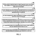
- FIG. 2 is a flow diagram which illustrates an illustrative method for making a series of panels with increasing moisture content and obtaining the bond strength properties with increasing moisture content.
- FIG. 3 is a flow diagram, which illustrates a way to validate the calibration model for moisture measurement in composite materials.
- FIG. 4 is a graph, which illustrates near infrared spectra on 100 scans of moist and dry composite material tape using first derivative data with 5 smoothing points.
- FIG. 5 is a graph, which illustrates mid infrared spectra of an average of 128 scans of moist and dry composite material tape using first derivative data with 7 smoothing points.
- FIG. 6 is a graph, which illustrates baseline offset corrected mid infrared data on 128 averaged scans of moist and dry composite material tape.
- FIG. 7 is a graph, which illustrates raw mid infrared data on 128 averaged scans of moist and dry composite material tape.
- FIG. 8 is a flow diagram of an aircraft production and service methodology.
- FIG. 9 is a block diagram of an aircraft.
- a flow diagram 100 which illustrates an illustrative method of obtaining a calibration between spectra of infrared energy and moisture content of composite material samples exposed to various quantities of moisture over various time periods is shown.
- composite material samples are provided with controlled moisture content information over the range of interest for good to poor bond strength results.
- the composite material samples may be 2-inch composite material squares, for example and without limitation.
- the composite material sample series is measured with the hand-held spectrometer that will be used to measure material in question later. This can be a spectra with the infrared spectra range only; such as near infrared or a mid infrared device for various materials and situations.
- the infrared data is preprocessed with an appropriate algorithm to provide the best data for the calibration of spectral data to moisture content.
- the multivariate calibration is preformed. This of often a Partial Least Squares (PLS) regression of moisture content data to the infrared spectra.
- PLS Partial Least Squares
- the calibration model is saved in an appropriate format and is loaded into the hand held device that will be used to make measurements of material in question.
- the calibration model in the spectrometer is used to predict moisture content on materials in question using new spectra on those materials.
- a flow diagram 200 which illustrates an illustrative method of making moisture content standards for the multivariate calibration and prediction method of FIG. 1 .
- a set of dried composite panels is provided and carefully weighted.
- the dry standards are measured with a hand-held infrared spectrometer in order to obtain the dry material spectra for all the dry standards.
- the surface of the composite material may be irradiated with near-spectrum or mid-spectrum infrared energy.
- the infrared spectra may be obtained using a hand-held spectrometer system such as that which is available from the Polychromix corp. or A2 Technologies, for example and without limitation.
- the dry standards are put into a heat and humidity chamber to increase their moisture content.
- the standards are weighed periodically until an increase of about 0.2%. With each increase of 0.2% weight a pair of standards are measured with a hand-held spectrometer and then the pair are bonded together in order to test the bond strength at the increased moisture content level.
- the bonded panels are cut to an appropriate size for the bond strength test and the bond strength test is performed.
- steps 208 and 210 are repeated until there is no further weight change or until the bond strength test results are consistently poor.
- a flow diagram 300 which illustrates an illustrative method for validating the multivariate model that was made for moisture content measurement is shown.
- the methods shown in FIG. 1 and the standards made in FIG. 2 are used to make an appropriate model of moisture content or reduction of bond strength with increasing moisture content versus changes in the infrared' spectra.
- a new set of standards is created using the same method that was illustrated in FIG. 2 and this new set panels is predicted for moisture content and bond strength with the method created in FIG. 1 .
- the multivariate model is validated by calculating the root mean square error of prediction from the prediction results in step 304 and the actual moisture content by weight percent increase.
- the model is optimized by using various data preprocessing and calibration methods to obtain the lowest possible prediction error in this validation step.
- FIGS. 4-7 graphs which illustrate infrared spectra obtained from composite materials having various degrees of moisture content are shown.
- a graph which illustrates near infrared spectra on 100 scans of moist and dry composite material tape using first derivative data with 5 smoothing points is shown.
- a graph which illustrates mid infrared spectra of an average of 128 scans of moist and dry composite material tape using first derivative data with 7 smoothing points is shown.
- FIG. 6 a graph, which illustrates baseline offset corrected mid-TR data on 128 averaged scans of moist and dry composite material tape is shown.
- a graph which illustrates raw mid-IR data on 128 averaged scans of moist and dry composite material tape is shown.
- embodiments of the disclosure may be used in the context of an aircraft manufacturing and service method 78 as shown in FIG. 8 and an aircraft 94 as shown in FIG. 9 .
- exemplary method 78 may include specification and design 80 of the aircraft 94 and material procurement 82 .
- component and subassembly manufacturing 84 and system integration 86 of the aircraft 94 takes place.
- the aircraft 94 may go through certification and delivery 88 in order to be placed in service 90 .
- the aircraft 94 may be scheduled for routine maintenance and service 92 (which may also include modification, reconfiguration, refurbishment, and so on).
- Each of the processes of method 78 may be performed or carried out by a system integrator, a third party, and/or an operator (e.g., a customer).
- a system integrator may include without limitation any number of aircraft manufacturers and major-system subcontractors
- a third party may include without limitation any number of vendors, subcontractors, and suppliers
- an operator may be an airline, leasing company, military entity, service organization, and so on.
- the aircraft 94 produced by exemplary method 78 may include an airframe 98 with a plurality of systems 96 and an interior 100 .
- high-level systems 96 include one or more of a propulsion system 102 , an electrical system 104 , a hydraulic system 106 , and an environmental system 108 . Any number of other systems may be included.
- an aerospace example is shown, the principles of the invention may be applied to other industries, such as the automotive industry.
- the apparatus embodied herein may be employed during any one or more of the stages of the production and service method 78 .
- components or subassemblies corresponding to production process 84 may be fabricated or manufactured in a manner similar to components or subassemblies produced while the aircraft 94 is in service.
- one or more apparatus embodiments may be utilized during the production stages 84 and 86 , for example, by substantially expediting assembly of or reducing the cost of an aircraft 94 .
- one or more apparatus embodiments may be utilized while the aircraft 94 is in service, for example and without limitation, to maintenance and service 92 .
Landscapes
- Physics & Mathematics (AREA)
- Spectroscopy & Molecular Physics (AREA)
- Health & Medical Sciences (AREA)
- Life Sciences & Earth Sciences (AREA)
- Chemical & Material Sciences (AREA)
- Analytical Chemistry (AREA)
- Biochemistry (AREA)
- General Health & Medical Sciences (AREA)
- General Physics & Mathematics (AREA)
- Immunology (AREA)
- Pathology (AREA)
- Investigating Or Analysing Materials By Optical Means (AREA)
Abstract
Description
Claims (21)
Priority Applications (5)
| Application Number | Priority Date | Filing Date | Title |
|---|---|---|---|
| US12/274,161 US7807971B2 (en) | 2008-11-19 | 2008-11-19 | Measurement of moisture in composite materials with near-IR and mid-IR spectroscopy |
| EP09752669.3A EP2366101B1 (en) | 2008-11-19 | 2009-11-11 | Determination of bond strength of a resin-fibre composite material based on moisture content measured using infared spectroscopy |
| KR1020117010471A KR101723692B1 (en) | 2008-11-19 | 2009-11-11 | Measurement of moisture in composite materials with near-IR and mid-IR spectroscopy |
| PCT/US2009/064054 WO2010059480A1 (en) | 2008-11-19 | 2009-11-11 | Measurement of moisture in composite materials with near-ir and mid-ir spectroscopy |
| JP2011536444A JP5753786B2 (en) | 2008-11-19 | 2009-11-11 | Measurement of moisture content in composite materials by near-infrared and mid-infrared spectroscopy |
Applications Claiming Priority (1)
| Application Number | Priority Date | Filing Date | Title |
|---|---|---|---|
| US12/274,161 US7807971B2 (en) | 2008-11-19 | 2008-11-19 | Measurement of moisture in composite materials with near-IR and mid-IR spectroscopy |
Publications (2)
| Publication Number | Publication Date |
|---|---|
| US20100123079A1 US20100123079A1 (en) | 2010-05-20 |
| US7807971B2 true US7807971B2 (en) | 2010-10-05 |
Family
ID=41570056
Family Applications (1)
| Application Number | Title | Priority Date | Filing Date |
|---|---|---|---|
| US12/274,161 Active US7807971B2 (en) | 2008-11-19 | 2008-11-19 | Measurement of moisture in composite materials with near-IR and mid-IR spectroscopy |
Country Status (5)
| Country | Link |
|---|---|
| US (1) | US7807971B2 (en) |
| EP (1) | EP2366101B1 (en) |
| JP (1) | JP5753786B2 (en) |
| KR (1) | KR101723692B1 (en) |
| WO (1) | WO2010059480A1 (en) |
Cited By (3)
| Publication number | Priority date | Publication date | Assignee | Title |
|---|---|---|---|---|
| US20160334380A1 (en) * | 2015-05-11 | 2016-11-17 | Airbus Defence and Space GmbH | Testing of components for contaminations |
| EP3282243A1 (en) | 2016-08-11 | 2018-02-14 | Airbus Defence and Space GmbH | Method and measuring system for determining the moisture content of a fiber composite component |
| US10983078B2 (en) | 2015-06-22 | 2021-04-20 | The Boeing Company | Methods and systems for designing a composite structure |
Families Citing this family (8)
| Publication number | Priority date | Publication date | Assignee | Title |
|---|---|---|---|---|
| US9087626B2 (en) | 2011-10-31 | 2015-07-21 | CNano Technology Limited | Measuring moisture in a CNT based fluid or paste |
| EP2669659A1 (en) * | 2012-06-01 | 2013-12-04 | ABB Schweiz AG | Method for calibrating a raw material analysis system |
| CN111220564B (en) * | 2019-12-31 | 2023-04-04 | 长春理工大学 | Terahertz detection optimization method for bonding pressurization parameters of multilayer structure |
| CN111579525B (en) * | 2020-05-15 | 2023-10-20 | 甘肃银光化学工业集团有限公司 | Device for automatically detecting water content of powdery energetic material |
| CN113834795B (en) * | 2020-06-08 | 2024-12-03 | 上海医药集团股份有限公司 | Online quantitative model of moisture content in hydroxychloroquine sulfate granules using near-infrared spectroscopy and its establishment method and detection method |
| CN112086137B (en) * | 2020-08-18 | 2022-06-10 | 山东金璋隆祥智能科技有限责任公司 | Method for quantitatively analyzing sorbose content in fermentation liquor |
| KR102624476B1 (en) * | 2021-12-24 | 2024-01-12 | 충남대학교산학협력단 | Method of detecting soil contaminated with petroleum compounds using hyperspectral analysis |
| CN118090648B (en) * | 2024-04-02 | 2024-06-21 | 常州建昊建筑鉴定检测有限公司 | Method and system for detecting water content of engineering material |
Citations (12)
| Publication number | Priority date | Publication date | Assignee | Title |
|---|---|---|---|---|
| US5104488A (en) * | 1987-10-05 | 1992-04-14 | Measurex Corporation | System and process for continuous determination and control of paper strength |
| US5107118A (en) * | 1990-10-01 | 1992-04-21 | Uop | Measurement of water levels in liquid hydrocarbon media |
| US6074483A (en) * | 1997-06-02 | 2000-06-13 | Honeywell-Measurex Corporation | Coating weight measuring and control apparatus and method |
| US20020109093A1 (en) * | 2000-12-13 | 2002-08-15 | Kelley Stephen S. | Method of predicting mechanical properties of decayed wood |
| US20020113212A1 (en) * | 2000-12-15 | 2002-08-22 | Meglen Robert R. | Use of a region of the visible and near infrared spectrum to predict mechanical properties of wet wood and standing trees |
| US6784431B2 (en) | 2002-06-13 | 2004-08-31 | The Boeing Company | Method of measuring anodize coating amount using infrared absorbance |
| US6794651B2 (en) | 2002-06-13 | 2004-09-21 | The Boeing Company | Method of measuring chromated conversion coating amount using infrared absorbance |
| US6903339B2 (en) | 2002-11-26 | 2005-06-07 | The Boeing Company | Method of measuring thickness of an opaque coating using infrared absorbance |
| US6906327B2 (en) | 2002-11-26 | 2005-06-14 | The Boeing Company | Method of measuring amount of chemical cure and amount of surface contamination using infrared absorbance |
| US7115869B2 (en) | 2003-09-30 | 2006-10-03 | The Boeing Company | Method for measurement of composite heat damage with infrared spectroscopy |
| US20070131862A1 (en) * | 2005-12-13 | 2007-06-14 | Huber Engineered Woods L.L.C. | Method using NIR spectroscopy to monitor components of engineered wood products |
| WO2009064054A1 (en) | 2007-11-13 | 2009-05-22 | Samsung Electronics Co., Ltd. | Method and apparatus to detect voice activity |
Family Cites Families (4)
| Publication number | Priority date | Publication date | Assignee | Title |
|---|---|---|---|---|
| SE9502611D0 (en) * | 1995-07-14 | 1995-07-14 | Casco Nobel Ab | Prediction of the properties of board |
| SE523308E (en) | 2000-03-02 | 2007-12-27 | Valmet Fibertech Ab | Method for Continuous Determination of Properties of a Wood Fiber Flow for Wood Fiber Disc Production |
| KR100398362B1 (en) * | 2000-09-01 | 2003-09-19 | 스펙트론 테크 주식회사 | Method and apparatus for measuring skin moisture by using near-infrared reflectance spectroscopy |
| US7402269B2 (en) * | 2005-10-25 | 2008-07-22 | The Boeing Company | Environmentally stable hybrid fabric system for exterior protection of an aircraft |
-
2008
- 2008-11-19 US US12/274,161 patent/US7807971B2/en active Active
-
2009
- 2009-11-11 JP JP2011536444A patent/JP5753786B2/en active Active
- 2009-11-11 WO PCT/US2009/064054 patent/WO2010059480A1/en not_active Ceased
- 2009-11-11 KR KR1020117010471A patent/KR101723692B1/en active Active
- 2009-11-11 EP EP09752669.3A patent/EP2366101B1/en active Active
Patent Citations (13)
| Publication number | Priority date | Publication date | Assignee | Title |
|---|---|---|---|---|
| US5104488A (en) * | 1987-10-05 | 1992-04-14 | Measurex Corporation | System and process for continuous determination and control of paper strength |
| US5107118A (en) * | 1990-10-01 | 1992-04-21 | Uop | Measurement of water levels in liquid hydrocarbon media |
| US6074483A (en) * | 1997-06-02 | 2000-06-13 | Honeywell-Measurex Corporation | Coating weight measuring and control apparatus and method |
| US20020109093A1 (en) * | 2000-12-13 | 2002-08-15 | Kelley Stephen S. | Method of predicting mechanical properties of decayed wood |
| US20020113212A1 (en) * | 2000-12-15 | 2002-08-22 | Meglen Robert R. | Use of a region of the visible and near infrared spectrum to predict mechanical properties of wet wood and standing trees |
| US6794651B2 (en) | 2002-06-13 | 2004-09-21 | The Boeing Company | Method of measuring chromated conversion coating amount using infrared absorbance |
| US6784431B2 (en) | 2002-06-13 | 2004-08-31 | The Boeing Company | Method of measuring anodize coating amount using infrared absorbance |
| US6903339B2 (en) | 2002-11-26 | 2005-06-07 | The Boeing Company | Method of measuring thickness of an opaque coating using infrared absorbance |
| US6906327B2 (en) | 2002-11-26 | 2005-06-14 | The Boeing Company | Method of measuring amount of chemical cure and amount of surface contamination using infrared absorbance |
| US7223977B2 (en) | 2002-11-26 | 2007-05-29 | The Boeing Company | Method of measuring thickness of an opaque coating using near-infrared absorbance |
| US7115869B2 (en) | 2003-09-30 | 2006-10-03 | The Boeing Company | Method for measurement of composite heat damage with infrared spectroscopy |
| US20070131862A1 (en) * | 2005-12-13 | 2007-06-14 | Huber Engineered Woods L.L.C. | Method using NIR spectroscopy to monitor components of engineered wood products |
| WO2009064054A1 (en) | 2007-11-13 | 2009-05-22 | Samsung Electronics Co., Ltd. | Method and apparatus to detect voice activity |
Non-Patent Citations (2)
| Title |
|---|
| Dao et al., "Accelerated ageing versus realistic ageing in a aerospace composite materials. IV. Hot/Wet ageing effects in a low temperature cure epoxy composite," 2007, Journal of Applied Polymer Science, vol. 106, pp. 4264-4276. * |
| Wichita State University, Bill Stevenson, Dept. of Chemistry, Methods for the Evaluation of Carbon Based Composite Surfaces for Subsequent Adhesive Bonding. |
Cited By (3)
| Publication number | Priority date | Publication date | Assignee | Title |
|---|---|---|---|---|
| US20160334380A1 (en) * | 2015-05-11 | 2016-11-17 | Airbus Defence and Space GmbH | Testing of components for contaminations |
| US10983078B2 (en) | 2015-06-22 | 2021-04-20 | The Boeing Company | Methods and systems for designing a composite structure |
| EP3282243A1 (en) | 2016-08-11 | 2018-02-14 | Airbus Defence and Space GmbH | Method and measuring system for determining the moisture content of a fiber composite component |
Also Published As
| Publication number | Publication date |
|---|---|
| US20100123079A1 (en) | 2010-05-20 |
| KR20110095252A (en) | 2011-08-24 |
| WO2010059480A1 (en) | 2010-05-27 |
| JP5753786B2 (en) | 2015-07-22 |
| EP2366101A1 (en) | 2011-09-21 |
| EP2366101B1 (en) | 2018-10-31 |
| KR101723692B1 (en) | 2017-04-05 |
| JP2012509461A (en) | 2012-04-19 |
Similar Documents
| Publication | Publication Date | Title |
|---|---|---|
| US7807971B2 (en) | Measurement of moisture in composite materials with near-IR and mid-IR spectroscopy | |
| US7919753B2 (en) | Method for performing IR spectroscopy measurements to quantify a level of UV effect | |
| US7956327B2 (en) | Method for determining degree of aging of a polymer resin material | |
| US8552382B2 (en) | Thermal effect measurement with mid-infrared spectroscopy | |
| US7915586B2 (en) | Method for performing mid-IR spectroscopy measurements to measure film coating thickness, weight and/or film composition | |
| US8536529B2 (en) | Non-contact surface chemistry measurement apparatus and method | |
| JP5954920B2 (en) | Classification method of resin type of carbon fiber reinforced plastic material using infrared spectroscopy | |
| US7279684B2 (en) | Method using NIR spectroscopy to monitor components of engineered wood products | |
| US8338787B1 (en) | System and method for resin thickness measurement | |
| US7800069B2 (en) | Method for performing IR spectroscopy measurements to determine coating weight/amount for metal conversion coatings | |
| US8330109B2 (en) | Method for determining contamination of material using Mid-IR spectroscopy | |
| US8436311B2 (en) | Method of predicting thermal or chemical effect in a coated or painted composite material | |
| Sandak et al. | Feasibility of portable NIR spectrometer for quality assurance in glue-laminated timber production | |
| Jones et al. | Monitoring ambient-temperature aging of a carbon-fiber/epoxy composite prepreg with photoacoustic spectroscopy | |
| US8519337B2 (en) | Thermal effect measurement with near-infrared spectroscopy | |
| CN106053380A (en) | Method for quickly analyzing proportions of tree species of mixed pulp wood by aid of near infrared spectrum technologies | |
| Liang et al. | Nondestructive determination of the compressive strength of wood using near-infrared spectroscopy | |
| Inagaki et al. | NIR spectral–kinetic analysis for thermally degraded Sugi (Cryptomeria japonica) wood | |
| US7645991B1 (en) | Method of using IR spectroscopy to determine presence of metallic material in polymer composite material | |
| Higgins | Non-Destructive Evaluation of Composite Thermal Damage with Agilent’s New Handheld 4300 FTIR | |
| CN116046714B (en) | Method for establishing a detection model for the content of resin and/or volatile matter in poly(phenylene ether) thermoplastic prepreg tapes and its application | |
| Jiang et al. | Non-contact quality monitoring of laid fabric carbon/epoxy resin prepreg using near infrared spectroscopy |
Legal Events
| Date | Code | Title | Description |
|---|---|---|---|
| AS | Assignment |
Owner name: BOEING COMPANY, THE,MICHIGAN Free format text: ASSIGNMENT OF ASSIGNORS INTEREST;ASSIGNORS:GRACE, WILLIAM B.;WERNER, GREGORY J.;SHELLEY, PAUL H.;REEL/FRAME:021862/0751 Effective date: 20081117 Owner name: BOEING COMPANY, THE, MICHIGAN Free format text: ASSIGNMENT OF ASSIGNORS INTEREST;ASSIGNORS:GRACE, WILLIAM B.;WERNER, GREGORY J.;SHELLEY, PAUL H.;REEL/FRAME:021862/0751 Effective date: 20081117 |
|
| STCF | Information on status: patent grant |
Free format text: PATENTED CASE |
|
| FPAY | Fee payment |
Year of fee payment: 4 |
|
| MAFP | Maintenance fee payment |
Free format text: PAYMENT OF MAINTENANCE FEE, 8TH YEAR, LARGE ENTITY (ORIGINAL EVENT CODE: M1552) Year of fee payment: 8 |
|
| MAFP | Maintenance fee payment |
Free format text: PAYMENT OF MAINTENANCE FEE, 12TH YEAR, LARGE ENTITY (ORIGINAL EVENT CODE: M1553); ENTITY STATUS OF PATENT OWNER: LARGE ENTITY Year of fee payment: 12 |