US7807919B2 - Apparatuses and methods to reduce safety risks associated with photovoltaic systems - Google Patents
Apparatuses and methods to reduce safety risks associated with photovoltaic systems Download PDFInfo
- Publication number
- US7807919B2 US7807919B2 US12/366,597 US36659709A US7807919B2 US 7807919 B2 US7807919 B2 US 7807919B2 US 36659709 A US36659709 A US 36659709A US 7807919 B2 US7807919 B2 US 7807919B2
- Authority
- US
- United States
- Prior art keywords
- switch
- photovoltaic
- photovoltaic panel
- connector
- safety switch
- Prior art date
- Legal status (The legal status is an assumption and is not a legal conclusion. Google has not performed a legal analysis and makes no representation as to the accuracy of the status listed.)
- Active
Links
- 238000000034 method Methods 0.000 title abstract description 8
- 238000009434 installation Methods 0.000 abstract description 13
- 235000014676 Phragmites communis Nutrition 0.000 description 15
- 230000003287 optical effect Effects 0.000 description 9
- 238000012423 maintenance Methods 0.000 description 7
- 239000004065 semiconductor Substances 0.000 description 6
- 238000013459 approach Methods 0.000 description 5
- 239000000463 material Substances 0.000 description 3
- 230000000007 visual effect Effects 0.000 description 3
- 230000005669 field effect Effects 0.000 description 2
- 231100000518 lethal Toxicity 0.000 description 2
- 230000001665 lethal effect Effects 0.000 description 2
- 238000012545 processing Methods 0.000 description 2
- 229910002065 alloy metal Inorganic materials 0.000 description 1
- 239000004020 conductor Substances 0.000 description 1
- 238000013461 design Methods 0.000 description 1
- 238000011161 development Methods 0.000 description 1
- 239000003989 dielectric material Substances 0.000 description 1
- 230000010354 integration Effects 0.000 description 1
- 229910052751 metal Inorganic materials 0.000 description 1
- 239000002184 metal Substances 0.000 description 1
- 238000012986 modification Methods 0.000 description 1
- 230000004048 modification Effects 0.000 description 1
- 230000035939 shock Effects 0.000 description 1
- 238000013024 troubleshooting Methods 0.000 description 1
Images


Classifications
-
- H—ELECTRICITY
- H01—ELECTRIC ELEMENTS
- H01L—SEMICONDUCTOR DEVICES NOT COVERED BY CLASS H10
- H01L31/00—Semiconductor devices sensitive to infrared radiation, light, electromagnetic radiation of shorter wavelength or corpuscular radiation and specially adapted either for the conversion of the energy of such radiation into electrical energy or for the control of electrical energy by such radiation; Processes or apparatus specially adapted for the manufacture or treatment thereof or of parts thereof; Details thereof
- H01L31/02—Details
- H01L31/02016—Circuit arrangements of general character for the devices
- H01L31/02019—Circuit arrangements of general character for the devices for devices characterised by at least one potential jump barrier or surface barrier
- H01L31/02021—Circuit arrangements of general character for the devices for devices characterised by at least one potential jump barrier or surface barrier for solar cells
-
- H—ELECTRICITY
- H02—GENERATION; CONVERSION OR DISTRIBUTION OF ELECTRIC POWER
- H02S—GENERATION OF ELECTRIC POWER BY CONVERSION OF INFRARED RADIATION, VISIBLE LIGHT OR ULTRAVIOLET LIGHT, e.g. USING PHOTOVOLTAIC [PV] MODULES
- H02S40/00—Components or accessories in combination with PV modules, not provided for in groups H02S10/00 - H02S30/00
- H02S40/30—Electrical components
- H02S40/34—Electrical components comprising specially adapted electrical connection means to be structurally associated with the PV module, e.g. junction boxes
-
- Y—GENERAL TAGGING OF NEW TECHNOLOGICAL DEVELOPMENTS; GENERAL TAGGING OF CROSS-SECTIONAL TECHNOLOGIES SPANNING OVER SEVERAL SECTIONS OF THE IPC; TECHNICAL SUBJECTS COVERED BY FORMER USPC CROSS-REFERENCE ART COLLECTIONS [XRACs] AND DIGESTS
- Y02—TECHNOLOGIES OR APPLICATIONS FOR MITIGATION OR ADAPTATION AGAINST CLIMATE CHANGE
- Y02E—REDUCTION OF GREENHOUSE GAS [GHG] EMISSIONS, RELATED TO ENERGY GENERATION, TRANSMISSION OR DISTRIBUTION
- Y02E10/00—Energy generation through renewable energy sources
- Y02E10/50—Photovoltaic [PV] energy
Definitions
- At least some embodiments disclosed herein relate to photovoltaic systems in general and, more particularly but not limited to, safety devices for the shipment, installation and/or maintenance of photovoltaic systems.
- a lethal voltage potential may be present.
- the possible voltage could be as high as 600 volts, while in Europe and the rest of the world this voltage could approach a kilovolt.
- Another recommendation is to install and/or service the photovoltaic panels at night when there is minimal risk of the panels being energized. This approach presents the potential safety risks associated from working in a poorly lighted environment.
- Apparatuses and methods to reduce safety risks associated with photovoltaic systems by providing a safety switch on a photovoltaic panel Some embodiments are summarized in this section.
- a photovoltaic panel includes: at least one photovoltaic cell; a connector to output energy from the photovoltaic panel; and a switch coupled between the at least one photovoltaic cell and the connector.
- the switch is configured to disconnect the at least one photovoltaic cell from the connector during installation of the photovoltaic panel, and to connect the at least one photovoltaic cell with the connector after installation of the photovoltaic panel.
- the photovoltaic panel further includes a junction box to host the connector, wherein the switch is integrated in the junction box.
- the switch includes a first conductive contactor, a second conductive contactor, and a removable portion which when removed connects the at least one photovoltaic cell with the connector.
- the removable portion may include a dielectric separator; when the dielectric separator is inserted between the first and second contactor, the switch is not connected; and when the dielectric separate is removed, the switch is connected.
- the first and second conductive contactors are spring loaded toward each other.
- the removable portion further includes a flag attached to the dielectric separator.
- the flag may have a visual indication of warning for electric shock.
- the switch includes a reed switch; and the removable portion includes a magnet.
- the reed switch may be a normally closed reed switch, or normally open reed switch.
- the switch includes an optical sensor to turn on or off the switch based on light detected by the optical sensor; and the removable portion includes a pull-tab configured to shield the optical sensor.
- the at least one photovoltaic cell may be used to power the optical sensor.
- the switch further includes a semiconductor switch device (e.g., a Field-Effect Transistor (FET)) or a relay.
- a semiconductor switch device e.g., a Field-Effect Transistor (FET)
- FET Field-Effect Transistor
- the switch includes a relay and a wiring connector to control the relay from a remote location.
- the photovoltaic panel further includes a circuit to detect a load from an inverter.
- the switch is to connect an output of the photovoltaic panel to the connector when the circuit detects a load from an inverter and to disconnect the output in absence of a load from an inverter.
- a photovoltaic panel module includes: a voltage module to adjust an output of a plurality of photovoltaic cells; and a switch coupled the voltage module to selectively provide the output.
- the voltage module outputs an alternating current (AC) output.
- the switch may include a semiconductor switch, a relay, a reed switch, a spring loaded switch, and/or an optical sensor to control a state of the switch.
- the photovoltaic panel module further includes connectors for wirings to control a state of the switch.
- the disclosure includes methods and apparatuses which perform these methods, including data processing systems which perform these methods, and computer readable media containing instructions which when executed on data processing systems cause the systems to perform these methods.
- FIG. 1 illustrates a solar panel having a safety switch according to one embodiment.
- FIGS. 2-5 illustrate a spring loaded safety switch for a photovoltaic panel according to one embodiment.
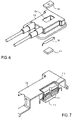
- FIGS. 6-7 illustrate a junction box with a reed switch for a photovoltaic panel according to one embodiment.
- FIG. 8 illustrates an optical sensor to control a safety switch for a photovoltaic panel according to one embodiment.
- FIG. 9 illustrates a solar panel having a safety switch controlled via auxiliary wiring according to one embodiment.
- One embodiment of the disclosure provides a method and system to reduce the safety risks during the shipment, installation and/or maintenance of photovoltaic systems, without introducing the risks associated with other approaches, such as covering them with an opaque material or working on them at night.
- safety protection is provided via the inclusion of a normally closed switch integral to the panel junction box or integral to the panel module when alternating current (AC) or direct current (DC) modules are used.
- AC alternating current
- DC direct current
- FIG. 1 illustrates a solar panel having a safety switch according to one embodiment.
- a solar panel 10 e.g., a photovoltaic panel
- includes at least one solar cell 12 e.g., a photovoltaic cell
- a voltage module 14 to adjust or regulate the output voltage (or in some other cases a current module to regulate current)
- a switch 16 to selectively isolate the solar cell 12 from the output connectors of the solar panel.
- the switch may be incorporated into regulator modules, such as voltage module 14 .
- the switch 16 is a normally closed switch. During the shipment, installation and/or maintenance, the switch 16 is placed in an open state to isolate the solar cell 12 from the output. After the installation or maintenance, the switch 16 is placed into a closed state to allow the solar cell 12 to energize the output connectors of the solar panel and to supply power through the output connectors of the solar panel.
- the switch 16 and the voltage module can be integrated into the junction box of the solar panel.
- the switch 16 is integrated with the voltage module 14 as a panel module.
- FIGS. 2-5 illustrate a spring loaded safety switch for a photovoltaic panel according to one embodiment.
- the switch includes two contactors 102 and 103 made of a conductive metal or plated hybrid.
- the contactors 102 and 103 are normally made of a spring alloy metal or have an integral spring plunger design (not shown).
- the contactors 102 and 103 are positioned or fixed in such a way that the two contacts 102 and 103 are spring loaded toward each other to maintain electrical continuity between the two contactors 102 and 103 .
- the switch is normally closed (NC) and not in a safe mode for installation or maintenance.
- a safe mode for installation or maintenance is achieved when the blade 104 is inserted between the two contactors 102 and 103 .
- the blade 104 is manufactured from a dielectric material and when inserted between the two contactors 102 and 103 there is no electrical continuity between the contactors 102 and 103 .
- the blade 104 may also have a flag 105 attached.
- the flag 105 could be red or some other highly visible color, to provide a visual indicator of the state of the panel.
- the panels and/or panel with integral modules would come shipped from the factory with the blade 104 and the flag 105 , where the blade 104 is inserted between the two contactors 102 and 103 .
- the panels would be installed and integrated with the blade 104 present and flag 105 visible.
- the installer would mount, secure, and plug in all of the connections in the system, including the grounding.
- the installer would remove the blades 104 at all those places indicated by the flags 105 .
- the spring loaded contactors 102 and 103 contact each other to provide an electric path from the photovoltaic cells to the output connectors of the photovoltaic panel.
- the blade(s) 104 and flag(s) 105 could be reinserted, aided by the tapered section 207 of the blade 104 , thereby breaking the electrical continuity between the contactors 102 and 103 at point 206 .
- contactors 102 and 103 there is symmetry in contactors 102 and 103 .
- the contactors 102 and 103 are not identical or even similar.
- the contactors 102 and 103 are made of electrically conductive material and configured to be in physical contact with each so that an electrically conductive path 206 is maintained, after the blade 104 is removed.
- the electrical conductive path 206 is maintained without the blade 104 being inserted between the contactors 102 and 103 , then disrupted by the blade 104 inserted between the contactors 102 and 103 , and then reestablished by the reinsertions of a dielectric device such as the blade 104 .
- the flags could also provide information in the form of text, such as, for example, “Remove before operation” or a warning of potentially lethal voltage.
- FIG. 4 illustrates a configuration of a spring loaded switch integrated with a junction box 308 of a photovoltaic panel.
- the junction box 308 includes a connector to connect the solar power generated by the photovoltaic panel to a load (e.g., an inverter, a voltage bus, etc.) via a cable 307 .
- a load e.g., an inverter, a voltage bus, etc.
- the blade 104 is inserted into the switch, with the flag 105 visible, the voltage generated by the solar cells is isolated from the connector for the cable 307 ; and thus it is safe to install the photovoltaic panel or to perform maintenance operations on the photovoltaic panel.
- FIG. 5 shows the components of the spring loaded switch and the junction box of a photovoltaic panel.
- the junction box 308 has an opening 409 , which provides access to remove the blade 104 and/or to re-insert the blade 104 .
- the contactors 103 of the switch can be attached to the junction box 308 via fastening the portion 401 to a supporting member of the junction box 308 , such as a printed circuit board (PCB).
- PCB printed circuit board
- FIGS. 6-7 illustrate a junction box with a reed switch for a photovoltaic panel according to one embodiment.
- FIG. 6 shows an assembly of a reed switch 510 and magnets for integrated into the photovoltaic junction box 308 .
- FIG. 7 shows a cut-away section illustrating the reed switch 510 and the magnets 511 and 512 installed within the portion 509 of the junction box 308 .
- a reed switch 510 is made normally closed by integrating a stationary biasing magnet 511 into the junction box 308 in close proximity to the normally open reed switch, so that the switch 510 is closed in absence of the magnet 512 .
- the magnet 512 is inserted into the junction box well 509 so that the reversed polarity cancels the magnetic lines of force and the reed switch 510 opens.
- the magnet 512 is installed in the junction box well 509 at the factory; and a flag 105 (not shown in FIGS. 6 and 7 ) is attached to the magnet 512 .
- the magnet 512 is removable and/or re-insertable via the junction box well 509 .
- normally closed (NC) reed contacts can be used to replace the normally open (NO) reed contacts 510 and the magnet 511 , avoiding the need for the additional stationary magnet.
- the magnet 512 is removed and may be discarded.
- the power leads of the junction box 308 can then be energized via the semiconductor switch or relay (not shown), when the reed switch 512 is in the closed state.
- a semiconductor switch (not shown in FIG. 7 ) can be used to energize the power leads of the junction box 308 .
- the panel junction box 308 or inverter may include a controller unit with a watchdog circuit configured to send a signal periodically (e.g., every time interval t) to maintain the connection of the panel outputs to the string. When this signal is timed-out or is absent, the panel outputs of the panel are disconnected via a semiconductor switch device (not shown).
- FIG. 8 illustrates an optical sensor to control a safety switch for a photovoltaic panel according to one embodiment.
- an optical sensor unit 700 with an optical sensor 701 is mounted on a printed circuit board (PCB) 711 .
- PCB printed circuit board
- springs 702 and 712 hold a separator 703 in place that can be removed in direction of arrow 704 using a pull-tab similar to the flag 105 discussed earlier.
- the exterior enclosure that would contain the mechanical elements such as the cable connections and the guide elements for guiding separator 703 in and out of the unit.
- additional circuitry (not shown in FIG. 8 ) will be on the side of the PCB 711 , such as a control circuit to affect an on/off switching either in some cases by FET (Field-Effect Transistor) transistors or using, in other cases, a relay, such as a bi-stable relay or another suitable circuit.
- FET Field-Effect Transistor
- a relay such as a bi-stable relay or another suitable circuit.
- the operational power may be drawn from the solar system itself, or it may be brought up by auxiliary wiring.
- a relay can be simply remote controlled by an auxiliary wire to close or open the circuit.
- the advantage of this approach is that no pull-tabs (flags or blades) can be forgotten on the roof.
- a mechanism and/or circuitry is integrated in the panel to identify the load from the inverter and connect the panel to the panel outputs when the load is detected. When no load is present the panel outputs is disconnected.
- This functionality would also be implemented using a semiconductor switch device or other suitable device (such as a relay), and some sensor circuitry, allowing an automatic reconnect when the loop appears to be closed and a load connected.
- FIG. 9 illustrates a solar panel having a safety switch controlled via auxiliary wiring according to one embodiment.
- a separate wire is connected to control the switch 16 from a remote location.
- the switch may be controlled via a signal from a watchdog circuit, from a remote switch or controller, etc.
Abstract
Description
Claims (6)
Priority Applications (2)
| Application Number | Priority Date | Filing Date | Title |
|---|---|---|---|
| US12/366,597 US7807919B2 (en) | 2007-11-02 | 2009-02-05 | Apparatuses and methods to reduce safety risks associated with photovoltaic systems |
| US12/628,977 US8933321B2 (en) | 2009-02-05 | 2009-12-01 | Systems and methods for an enhanced watchdog in solar module installations |
Applications Claiming Priority (3)
| Application Number | Priority Date | Filing Date | Title |
|---|---|---|---|
| US158707P | 2007-11-02 | 2007-11-02 | |
| US12/254,780 US7884278B2 (en) | 2007-11-02 | 2008-10-20 | Apparatuses and methods to reduce safety risks associated with photovoltaic systems |
| US12/366,597 US7807919B2 (en) | 2007-11-02 | 2009-02-05 | Apparatuses and methods to reduce safety risks associated with photovoltaic systems |
Related Parent Applications (1)
| Application Number | Title | Priority Date | Filing Date |
|---|---|---|---|
| US12/254,780 Continuation US7884278B2 (en) | 2007-11-02 | 2008-10-20 | Apparatuses and methods to reduce safety risks associated with photovoltaic systems |
Publications (2)
| Publication Number | Publication Date |
|---|---|
| US20090133736A1 US20090133736A1 (en) | 2009-05-28 |
| US7807919B2 true US7807919B2 (en) | 2010-10-05 |
Family
ID=40586903
Family Applications (3)
| Application Number | Title | Priority Date | Filing Date |
|---|---|---|---|
| US12/254,780 Active 2029-03-28 US7884278B2 (en) | 2007-11-02 | 2008-10-20 | Apparatuses and methods to reduce safety risks associated with photovoltaic systems |
| US12/366,597 Active US7807919B2 (en) | 2007-11-02 | 2009-02-05 | Apparatuses and methods to reduce safety risks associated with photovoltaic systems |
| US12/948,614 Abandoned US20110061713A1 (en) | 2007-11-02 | 2010-11-17 | Apparatuses and Methods to Reduce Safety Risks Associated with Photovoltaic Systems |
Family Applications Before (1)
| Application Number | Title | Priority Date | Filing Date |
|---|---|---|---|
| US12/254,780 Active 2029-03-28 US7884278B2 (en) | 2007-11-02 | 2008-10-20 | Apparatuses and methods to reduce safety risks associated with photovoltaic systems |
Family Applications After (1)
| Application Number | Title | Priority Date | Filing Date |
|---|---|---|---|
| US12/948,614 Abandoned US20110061713A1 (en) | 2007-11-02 | 2010-11-17 | Apparatuses and Methods to Reduce Safety Risks Associated with Photovoltaic Systems |
Country Status (10)
| Country | Link |
|---|---|
| US (3) | US7884278B2 (en) |
| EP (2) | EP2206159B1 (en) |
| JP (1) | JP2011503846A (en) |
| KR (1) | KR20100093072A (en) |
| CN (1) | CN101849292B (en) |
| AU (1) | AU2008318625A1 (en) |
| ES (1) | ES2954070T3 (en) |
| IL (1) | IL205312A0 (en) |
| PL (1) | PL2206159T3 (en) |
| WO (1) | WO2009059028A2 (en) |
Cited By (65)
| Publication number | Priority date | Publication date | Assignee | Title |
|---|---|---|---|---|
| US20100139734A1 (en) * | 2009-02-05 | 2010-06-10 | Tigo Energy | Systems and Methods for an Enhanced Watchdog in Solar Module Installations |
| US20100229915A1 (en) * | 2007-10-15 | 2010-09-16 | Ampt, Llc | Systems for Highly Efficient Solar Power |
| US20110061713A1 (en) * | 2007-11-02 | 2011-03-17 | Tigo Energy | Apparatuses and Methods to Reduce Safety Risks Associated with Photovoltaic Systems |
| US7919953B2 (en) | 2007-10-23 | 2011-04-05 | Ampt, Llc | Solar power capacitor alternative switch circuitry system for enhanced capacitor life |
| US20110088741A1 (en) * | 2009-10-19 | 2011-04-21 | Randy Richard Dunton | Solar Photovoltaic Module Safety Shutdown System |
| US20110172842A1 (en) * | 2009-12-29 | 2011-07-14 | Tigo Energy | Systems and Methods for Remote or Local Shut-Off of a Photovoltaic System |
| US20110218687A1 (en) * | 2007-11-02 | 2011-09-08 | Tigo Energy | System and Method for Enhanced Watch Dog in Solar Panel Installations |
| EP2495766A1 (en) | 2011-02-13 | 2012-09-05 | Fabio Brucchi | Safety system to reduce risk of electrocution at photovoltaic panels level |
| US9112379B2 (en) | 2006-12-06 | 2015-08-18 | Solaredge Technologies Ltd. | Pairing of components in a direct current distributed power generation system |
| US9130401B2 (en) | 2006-12-06 | 2015-09-08 | Solaredge Technologies Ltd. | Distributed power harvesting systems using DC power sources |
| US9235228B2 (en) | 2012-03-05 | 2016-01-12 | Solaredge Technologies Ltd. | Direct current link circuit |
| US9291696B2 (en) | 2007-12-05 | 2016-03-22 | Solaredge Technologies Ltd. | Photovoltaic system power tracking method |
| US9318974B2 (en) | 2014-03-26 | 2016-04-19 | Solaredge Technologies Ltd. | Multi-level inverter with flying capacitor topology |
| US9362743B2 (en) | 2008-05-05 | 2016-06-07 | Solaredge Technologies Ltd. | Direct current power combiner |
| US9368964B2 (en) | 2006-12-06 | 2016-06-14 | Solaredge Technologies Ltd. | Distributed power system using direct current power sources |
| US9397497B2 (en) | 2013-03-15 | 2016-07-19 | Ampt, Llc | High efficiency interleaved solar power supply system |
| US9401599B2 (en) | 2010-12-09 | 2016-07-26 | Solaredge Technologies Ltd. | Disconnection of a string carrying direct current power |
| US9407161B2 (en) | 2007-12-05 | 2016-08-02 | Solaredge Technologies Ltd. | Parallel connected inverters |
| US9442504B2 (en) | 2009-04-17 | 2016-09-13 | Ampt, Llc | Methods and apparatus for adaptive operation of solar power systems |
| US9466737B2 (en) | 2009-10-19 | 2016-10-11 | Ampt, Llc | Solar panel string converter topology |
| US9537445B2 (en) | 2008-12-04 | 2017-01-03 | Solaredge Technologies Ltd. | Testing of a photovoltaic panel |
| US9543889B2 (en) | 2006-12-06 | 2017-01-10 | Solaredge Technologies Ltd. | Distributed power harvesting systems using DC power sources |
| US9548619B2 (en) | 2013-03-14 | 2017-01-17 | Solaredge Technologies Ltd. | Method and apparatus for storing and depleting energy |
| US9590526B2 (en) | 2006-12-06 | 2017-03-07 | Solaredge Technologies Ltd. | Safety mechanisms, wake up and shutdown methods in distributed power installations |
| US9647442B2 (en) | 2010-11-09 | 2017-05-09 | Solaredge Technologies Ltd. | Arc detection and prevention in a power generation system |
| US9644993B2 (en) | 2006-12-06 | 2017-05-09 | Solaredge Technologies Ltd. | Monitoring of distributed power harvesting systems using DC power sources |
| US9673711B2 (en) | 2007-08-06 | 2017-06-06 | Solaredge Technologies Ltd. | Digital average input current control in power converter |
| US9680304B2 (en) | 2006-12-06 | 2017-06-13 | Solaredge Technologies Ltd. | Method for distributed power harvesting using DC power sources |
| US9812984B2 (en) | 2012-01-30 | 2017-11-07 | Solaredge Technologies Ltd. | Maximizing power in a photovoltaic distributed power system |
| US9819178B2 (en) | 2013-03-15 | 2017-11-14 | Solaredge Technologies Ltd. | Bypass mechanism |
| US9831824B2 (en) | 2007-12-05 | 2017-11-28 | SolareEdge Technologies Ltd. | Current sensing on a MOSFET |
| US9853565B2 (en) | 2012-01-30 | 2017-12-26 | Solaredge Technologies Ltd. | Maximized power in a photovoltaic distributed power system |
| US9853538B2 (en) | 2007-12-04 | 2017-12-26 | Solaredge Technologies Ltd. | Distributed power harvesting systems using DC power sources |
| US9866098B2 (en) | 2011-01-12 | 2018-01-09 | Solaredge Technologies Ltd. | Serially connected inverters |
| US9869701B2 (en) | 2009-05-26 | 2018-01-16 | Solaredge Technologies Ltd. | Theft detection and prevention in a power generation system |
| US9876430B2 (en) | 2008-03-24 | 2018-01-23 | Solaredge Technologies Ltd. | Zero voltage switching |
| US9923516B2 (en) | 2012-01-30 | 2018-03-20 | Solaredge Technologies Ltd. | Photovoltaic panel circuitry |
| US9941813B2 (en) | 2013-03-14 | 2018-04-10 | Solaredge Technologies Ltd. | High frequency multi-level inverter |
| US9941421B2 (en) | 2009-10-19 | 2018-04-10 | Helios Focus Llc | Solar photovaltaic module rapid shutdown and safety system |
| US9960667B2 (en) | 2006-12-06 | 2018-05-01 | Solaredge Technologies Ltd. | System and method for protection during inverter shutdown in distributed power installations |
| US9966766B2 (en) | 2006-12-06 | 2018-05-08 | Solaredge Technologies Ltd. | Battery power delivery module |
| US9991717B1 (en) | 2015-06-15 | 2018-06-05 | Roco, Llc | Method and apparatus for connecting and disconnecting a photovoltaic module to a distribution system |
| US10115841B2 (en) | 2012-06-04 | 2018-10-30 | Solaredge Technologies Ltd. | Integrated photovoltaic panel circuitry |
| US10121913B2 (en) | 2009-10-19 | 2018-11-06 | Helios Focus Llc | Solar photovoltaic module safety shutdown system |
| US10230310B2 (en) | 2016-04-05 | 2019-03-12 | Solaredge Technologies Ltd | Safety switch for photovoltaic systems |
| US10388802B2 (en) | 2015-07-06 | 2019-08-20 | SolarOff Systems, LLC | System and method for synchronized rapid shutdown of electrical devices |
| US10396662B2 (en) | 2011-09-12 | 2019-08-27 | Solaredge Technologies Ltd | Direct current link circuit |
| US10673229B2 (en) | 2010-11-09 | 2020-06-02 | Solaredge Technologies Ltd. | Arc detection and prevention in a power generation system |
| US10673222B2 (en) | 2010-11-09 | 2020-06-02 | Solaredge Technologies Ltd. | Arc detection and prevention in a power generation system |
| US10680443B2 (en) | 2013-12-12 | 2020-06-09 | Tsb Corporation | Solar power generation system |
| US10931119B2 (en) | 2012-01-11 | 2021-02-23 | Solaredge Technologies Ltd. | Photovoltaic module |
| US11018623B2 (en) | 2016-04-05 | 2021-05-25 | Solaredge Technologies Ltd. | Safety switch for photovoltaic systems |
| US11177663B2 (en) | 2016-04-05 | 2021-11-16 | Solaredge Technologies Ltd. | Chain of power devices |
| US11228278B2 (en) | 2007-11-02 | 2022-01-18 | Tigo Energy, Inc. | System and method for enhanced watch dog in solar panel installations |
| US11264947B2 (en) | 2007-12-05 | 2022-03-01 | Solaredge Technologies Ltd. | Testing of a photovoltaic panel |
| US11296650B2 (en) | 2006-12-06 | 2022-04-05 | Solaredge Technologies Ltd. | System and method for protection during inverter shutdown in distributed power installations |
| US11309832B2 (en) | 2006-12-06 | 2022-04-19 | Solaredge Technologies Ltd. | Distributed power harvesting systems using DC power sources |
| US11569660B2 (en) | 2006-12-06 | 2023-01-31 | Solaredge Technologies Ltd. | Distributed power harvesting systems using DC power sources |
| US11569659B2 (en) | 2006-12-06 | 2023-01-31 | Solaredge Technologies Ltd. | Distributed power harvesting systems using DC power sources |
| US11687112B2 (en) | 2006-12-06 | 2023-06-27 | Solaredge Technologies Ltd. | Distributed power harvesting systems using DC power sources |
| US11728768B2 (en) | 2006-12-06 | 2023-08-15 | Solaredge Technologies Ltd. | Pairing of components in a direct current distributed power generation system |
| US11735910B2 (en) | 2006-12-06 | 2023-08-22 | Solaredge Technologies Ltd. | Distributed power system using direct current power sources |
| US11855231B2 (en) | 2006-12-06 | 2023-12-26 | Solaredge Technologies Ltd. | Distributed power harvesting systems using DC power sources |
| US11881814B2 (en) | 2005-12-05 | 2024-01-23 | Solaredge Technologies Ltd. | Testing of a photovoltaic panel |
| US11888387B2 (en) | 2006-12-06 | 2024-01-30 | Solaredge Technologies Ltd. | Safety mechanisms, wake up and shutdown methods in distributed power installations |
Families Citing this family (49)
| Publication number | Priority date | Publication date | Assignee | Title |
|---|---|---|---|---|
| CA2490858A1 (en) | 2004-12-07 | 2006-06-07 | Ignis Innovation Inc. | Driving method for compensated voltage-programming of amoled displays |
| TW200707376A (en) | 2005-06-08 | 2007-02-16 | Ignis Innovation Inc | Method and system for driving a light emitting device display |
| US9489891B2 (en) | 2006-01-09 | 2016-11-08 | Ignis Innovation Inc. | Method and system for driving an active matrix display circuit |
| US9269322B2 (en) | 2006-01-09 | 2016-02-23 | Ignis Innovation Inc. | Method and system for driving an active matrix display circuit |
| EP2458579B1 (en) | 2006-01-09 | 2017-09-20 | Ignis Innovation Inc. | Method and system for driving an active matrix display circuit |
| CN102057418B (en) | 2008-04-18 | 2014-11-12 | 伊格尼斯创新公司 | System and driving method for light emitting device display |
| CA2637343A1 (en) | 2008-07-29 | 2010-01-29 | Ignis Innovation Inc. | Improving the display source driver |
| US9370075B2 (en) | 2008-12-09 | 2016-06-14 | Ignis Innovation Inc. | System and method for fast compensation programming of pixels in a display |
| US20100301670A1 (en) * | 2009-03-01 | 2010-12-02 | William Wilhelm | Dc peak power tracking devices, methods, and systems |
| IT1394746B1 (en) * | 2009-07-14 | 2012-07-13 | Infor System S R L | SYSTEM FOR THE INSTALLATION OF PHOTOVOLTAIC MODULES IN ELECTRICAL SAFETY CONDITIONS AND RELATED INSTALLATION METHOD. |
| CA2758815A1 (en) * | 2009-07-23 | 2011-01-27 | Enphase Energy, Inc. | Method and apparatus for detection and control of dc arc faults |
| ITMI20091879A1 (en) * | 2009-10-29 | 2011-04-30 | Infor System S R L | ELECTRIC SAFETY DEVICE FOR SOLAR SYSTEMS WITH PHOTOVOLTAIC PANELS AND SOLAR SYSTEM THAT INCORPORATES THIS LIFELINK SOLAR DEVICE. |
| US8283967B2 (en) | 2009-11-12 | 2012-10-09 | Ignis Innovation Inc. | Stable current source for system integration to display substrate |
| DE102009044695A1 (en) | 2009-11-27 | 2011-06-01 | Müller, Ingo, Dr. | Solar module, modular switch, solar cable, busbar, multi-contact connector |
| CA2687631A1 (en) | 2009-12-06 | 2011-06-06 | Ignis Innovation Inc | Low power driving scheme for display applications |
| CA2696778A1 (en) | 2010-03-17 | 2011-09-17 | Ignis Innovation Inc. | Lifetime, uniformity, parameter extraction methods |
| CN102386259A (en) * | 2010-09-02 | 2012-03-21 | 国琏电子(上海)有限公司 | Wiring box |
| AT510512B1 (en) * | 2010-09-30 | 2015-08-15 | Fronius Int Gmbh | INVERTER |
| WO2012149387A1 (en) * | 2011-04-27 | 2012-11-01 | Solarbridge Technologies, Inc. | Configurable power supply assembly |
| US8174856B2 (en) * | 2011-04-27 | 2012-05-08 | Solarbridge Technologies, Inc. | Configurable power supply assembly |
| US20140368491A1 (en) | 2013-03-08 | 2014-12-18 | Ignis Innovation Inc. | Pixel circuits for amoled displays |
| US9351368B2 (en) | 2013-03-08 | 2016-05-24 | Ignis Innovation Inc. | Pixel circuits for AMOLED displays |
| US9886899B2 (en) | 2011-05-17 | 2018-02-06 | Ignis Innovation Inc. | Pixel Circuits for AMOLED displays |
| WO2012164474A2 (en) | 2011-05-28 | 2012-12-06 | Ignis Innovation Inc. | System and method for fast compensation programming of pixels in a display |
| US9837556B2 (en) * | 2011-10-31 | 2017-12-05 | Volterra Semiconductor LLC | Integrated photovoltaic panel with sectional maximum power point tracking |
| US9747834B2 (en) | 2012-05-11 | 2017-08-29 | Ignis Innovation Inc. | Pixel circuits including feedback capacitors and reset capacitors, and display systems therefore |
| US20140153303A1 (en) * | 2012-11-30 | 2014-06-05 | SunEdison Microinverter Products LLC | Solar module having a back plane integrated inverter |
| US9786223B2 (en) | 2012-12-11 | 2017-10-10 | Ignis Innovation Inc. | Pixel circuits for AMOLED displays |
| US9336717B2 (en) | 2012-12-11 | 2016-05-10 | Ignis Innovation Inc. | Pixel circuits for AMOLED displays |
| CA2894717A1 (en) | 2015-06-19 | 2016-12-19 | Ignis Innovation Inc. | Optoelectronic device characterization in array with shared sense line |
| US9721505B2 (en) | 2013-03-08 | 2017-08-01 | Ignis Innovation Inc. | Pixel circuits for AMOLED displays |
| US20150236638A1 (en) * | 2013-04-13 | 2015-08-20 | Solexel, Inc. | Solar photovoltaic module power control and status monitoring system utilizing laminateembedded remote access module switch |
| WO2016032484A1 (en) * | 2014-08-28 | 2016-03-03 | E Gear Llc | Electrical combiner box with improved functionality |
| CA2873476A1 (en) | 2014-12-08 | 2016-06-08 | Ignis Innovation Inc. | Smart-pixel display architecture |
| CA2886862A1 (en) | 2015-04-01 | 2016-10-01 | Ignis Innovation Inc. | Adjusting display brightness for avoiding overheating and/or accelerated aging |
| MX2017015054A (en) * | 2015-05-26 | 2018-05-17 | Arcelormittal | Electrical connection device for a photovoltaic system. |
| DK3304728T3 (en) * | 2015-05-26 | 2021-09-06 | Arcelormittal | Electrical connection device to a photovoltaic system |
| US10657895B2 (en) | 2015-07-24 | 2020-05-19 | Ignis Innovation Inc. | Pixels and reference circuits and timing techniques |
| US10373554B2 (en) | 2015-07-24 | 2019-08-06 | Ignis Innovation Inc. | Pixels and reference circuits and timing techniques |
| CA2898282A1 (en) | 2015-07-24 | 2017-01-24 | Ignis Innovation Inc. | Hybrid calibration of current sources for current biased voltage progra mmed (cbvp) displays |
| CA2908285A1 (en) | 2015-10-14 | 2017-04-14 | Ignis Innovation Inc. | Driver with multiple color pixel structure |
| US10343545B2 (en) | 2016-01-15 | 2019-07-09 | Trumpet Holdings, Inc. | Systems and methods for separating batteries |
| US11190022B2 (en) | 2019-01-09 | 2021-11-30 | Texas Instruments Incorporated | Controller circuit for photovoltaic sub-module |
| US10778482B2 (en) | 2019-02-12 | 2020-09-15 | Texas Instruments Incorporated | Bit slicer circuit for S-FSK receiver, integrated circuit, and method associated therewith |
| US10797921B2 (en) | 2019-02-12 | 2020-10-06 | Texas Instruments Incorporated | Threshold computation circuit for S-FSK receiver, integrated circuit, and method associated therewith |
| US11342787B2 (en) | 2019-03-20 | 2022-05-24 | Texas Instruments Incorporated | Controller circuit for photovoltaic module |
| US11350186B2 (en) | 2019-03-20 | 2022-05-31 | Texas Instruments Incorporated | Monitoring circuit for photovoltaic module |
| CN113452043B (en) * | 2021-08-30 | 2022-01-11 | 广东电网有限责任公司湛江供电局 | Method, device, equipment and medium for governing three-phase unbalance of transformer area |
| CN117420377A (en) * | 2023-12-18 | 2024-01-19 | 西安现代控制技术研究所 | Multichannel relay array monitoring method |
Citations (58)
| Publication number | Priority date | Publication date | Assignee | Title |
|---|---|---|---|---|
| JPH04219982A (en) | 1990-12-20 | 1992-08-11 | Sanyo Electric Co Ltd | Solar battery panel and its connection |
| US5143556A (en) | 1989-03-13 | 1992-09-01 | Matlin Ronald W | Support for photovoltaic arrays |
| US5235266A (en) | 1990-06-02 | 1993-08-10 | Schottel-Werft Josef Becker Gmbh & Co. Kg | Energy-generating plant, particularly propeller-type ship's propulsion plant, including a solar generator |
| US5268832A (en) | 1991-08-20 | 1993-12-07 | Kabushiki Kaisha Toshiba | DC/AC inverter controller for solar cell, including maximum power point tracking function |
| US5280133A (en) | 1991-12-13 | 1994-01-18 | United Solar Systems Corporation | Junction box for a solar panel |
| DE4232356A1 (en) | 1992-09-26 | 1994-03-31 | Inst Solare Energieversorgungstechnik Iset | Power supply system with at least two rectifier-inverter pairs - has voltage from one pair phase-shifted with respect to other pair thus eliminating unwanted harmonics |
| JPH0897460A (en) | 1994-09-22 | 1996-04-12 | Nissin Electric Co Ltd | Solar cell power generator |
| JPH08116628A (en) | 1994-10-14 | 1996-05-07 | Nitto Kogyo Kk | Solar disconnecting switch |
| JPH08316517A (en) | 1995-05-17 | 1996-11-29 | Sanyo Electric Co Ltd | Solar battery device |
| US5604430A (en) | 1994-10-11 | 1997-02-18 | Trw Inc. | Solar array maximum power tracker with arcjet load |
| JPH09148611A (en) | 1995-11-24 | 1997-06-06 | Sanyo Electric Co Ltd | Solar battery device |
| JPH11103538A (en) | 1997-09-27 | 1999-04-13 | My Way Giken Kk | Optical power generating system |
| US5923158A (en) | 1996-08-30 | 1999-07-13 | Canon Kabushiki Kaisha | Power control apparatus for solar power generation system |
| US6031736A (en) | 1995-07-26 | 2000-02-29 | Canon Kabushiki Kaisha | Control apparatus of inverter and power generation system using such control apparatus |
| US6093885A (en) | 1998-03-03 | 2000-07-25 | Canon Kabushiki Kaisha | Photovoltaic power generating system |
| US6101073A (en) | 1997-06-13 | 2000-08-08 | Canon Kabushiki Kaisha | Ground fault protecting apparatus and method for solar power generation and solar power generation apparatus using the apparatus and method |
| JP2000358330A (en) | 1999-06-14 | 2000-12-26 | Nissin Electric Co Ltd | Photovoltaic power generating apparatus |
| DE19961705A1 (en) | 1999-12-21 | 2001-07-05 | Sma Regelsysteme Gmbh | Arrangement for decentralized supply of regenerative energy performs voltage regulation at combination point for controlled improvement of quality of electrical supply |
| US6275016B1 (en) | 2001-02-15 | 2001-08-14 | Texas Instruments Incorporated | Buck-boost switching regulator |
| US6396239B1 (en) | 2001-04-06 | 2002-05-28 | William M. Benn | Portable solar generator |
| US6448489B2 (en) | 2000-04-28 | 2002-09-10 | Sharp Kabushiki Kaisha | Solar generation system |
| US6515215B1 (en) | 1998-03-13 | 2003-02-04 | Canon Kabushiki Kaisha | Photovoltaic module, photovoltaic module array, photovoltaic system, and method of detecting failure of photovoltaic module |
| WO2003012569A1 (en) | 2001-07-29 | 2003-02-13 | Stichting Energieonderzoek Centrum Nederland | Maximum powerpoint tracker |
| US6545211B1 (en) | 1999-01-14 | 2003-04-08 | Canon Kabushiki Kaisha | Solar cell module, building material with solar cell module, solar cell module framing structure, and solar power generation apparatus |
| JP2003134661A (en) | 2001-10-17 | 2003-05-09 | Mitsubishi Heavy Ind Ltd | Load interruption detecting device and photovoltaic power generator |
| US6593520B2 (en) | 2000-02-29 | 2003-07-15 | Canon Kabushiki Kaisha | Solar power generation apparatus and control method therefor |
| US6650031B1 (en) | 1998-09-30 | 2003-11-18 | Siemens And Shell Solar Gmbh | Protective system for a solar module |
| US6653549B2 (en) | 2000-07-10 | 2003-11-25 | Canon Kabushiki Kaisha | Photovoltaic power generation systems and methods of controlling photovoltaic power generation systems |
| EP1388774A1 (en) | 2002-08-09 | 2004-02-11 | Alcatel | Source conditioning circuit at a maximum power point |
| US6837739B2 (en) * | 2003-01-31 | 2005-01-04 | Hewlett-Packard Development Company, L.P. | Battery connection interrupter |
| US6844739B2 (en) | 2001-03-09 | 2005-01-18 | National Institute Of Advanced Industrial Science And Technology | Maximum power point tracking method and device |
| US20050057215A1 (en) | 2003-09-15 | 2005-03-17 | Stefan Matan | Systems and methods for charging a battery |
| US20050057214A1 (en) | 2003-09-15 | 2005-03-17 | Stefan Matan | Systems and methods for generating renewable energy |
| US6894911B2 (en) | 2000-06-02 | 2005-05-17 | Iwatt, Inc. | Method of driving a power converter by using a power pulse and a sense pulse |
| US6897370B2 (en) | 2001-05-29 | 2005-05-24 | Canon Kabushiki Kaisha | Power generation apparatus and its control method |
| US20060001406A1 (en) | 2004-07-01 | 2006-01-05 | Stefan Matan | Power extractor circuit |
| US6984970B2 (en) | 2002-09-19 | 2006-01-10 | Alcatel | Conditioning circuit for a power supply at the maximum power point, a solar generator, and a conditioning method |
| AU2005262278A1 (en) | 2004-07-13 | 2006-01-19 | Tigo Energy, Inc. | A device for distributed maximum power tracking for solar arrays |
| ES2249147A1 (en) | 2004-07-01 | 2006-03-16 | Fundacion Robotiker | Intelligent photovoltaic module, has inverter that supplies alternating current to tracking algorithm point maximum power unit, and direct current to direct current converter controlled by maximum power unit |
| US7061214B2 (en) | 2003-11-25 | 2006-06-13 | Texas Instruments Incorporated | Single inductor dual output buck converter with frequency and time varying offset control |
| US20060174939A1 (en) | 2004-12-29 | 2006-08-10 | Isg Technologies Llc | Efficiency booster circuit and technique for maximizing power point tracking |
| US20060185727A1 (en) | 2004-12-29 | 2006-08-24 | Isg Technologies Llc | Converter circuit and technique for increasing the output efficiency of a variable power source |
| US20060231132A1 (en) | 2005-04-18 | 2006-10-19 | Thomas Neussner | Photovoltaic generator with thermo switch element |
| US7248946B2 (en) | 2004-05-11 | 2007-07-24 | Advanced Energy Conversion, Llc | Inverter control methodology for distributed generation sources connected to a utility grid |
| US7256566B2 (en) | 2003-05-02 | 2007-08-14 | Ballard Power Systems Corporation | Method and apparatus for determining a maximum power point of photovoltaic cells |
| US7276886B2 (en) | 2005-10-03 | 2007-10-02 | Texas Instruments Incorporated | Dual buck-boost converter with single inductor |
| US20070273351A1 (en) | 2004-07-01 | 2007-11-29 | Atira Technologies Llc | Dynamic switch power converter |
| US20080122449A1 (en) | 2006-11-27 | 2008-05-29 | Besser David A | Power extractor for impedance matching |
| US20080121272A1 (en) | 2006-11-27 | 2008-05-29 | Besser David A | System and apparatuses with multiple power extractors coupled to different power sources |
| US20080122518A1 (en) | 2006-11-27 | 2008-05-29 | Besser David A | Multi-Source, Multi-Load Systems with a Power Extractor |
| US20080142071A1 (en) | 2006-12-15 | 2008-06-19 | Miasole | Protovoltaic module utilizing a flex circuit for reconfiguration |
| US20080179949A1 (en) | 2006-11-27 | 2008-07-31 | Besser David A | Power extractor detecting a power change |
| US20080303503A1 (en) | 2004-07-13 | 2008-12-11 | Central Queensland University | Device For Distributed Maximum Power Tracking For Solar Arrays |
| US7518346B2 (en) | 2006-03-03 | 2009-04-14 | Texas Instruments Deutschland Gmbh | Buck-boost DC/DC converter with overlap control using ramp shift signal |
| US20090114263A1 (en) | 2007-11-02 | 2009-05-07 | Tigo Energy, Inc. | Apparatuses and Methods to Reduce Safety Risks Associated with Photovoltaic Systems |
| US7595616B2 (en) | 2004-05-28 | 2009-09-29 | Texas Instruments Deutschland Gmbh | Control circuit for a polarity inverting buck-boost DC-DC converter |
| US7605498B2 (en) | 2007-10-15 | 2009-10-20 | Ampt, Llc | Systems for highly efficient solar power conversion |
| US20100139734A1 (en) | 2009-02-05 | 2010-06-10 | Tigo Energy | Systems and Methods for an Enhanced Watchdog in Solar Module Installations |
Family Cites Families (30)
| Publication number | Priority date | Publication date | Assignee | Title |
|---|---|---|---|---|
| DE3010371A1 (en) * | 1980-03-15 | 1981-09-24 | Licentia Gmbh | Control output circuit for solar cells - has sensing circuit which switches cells through to converter when power output exceeds threshold |
| IT1250558B (en) * | 1991-12-30 | 1995-04-20 | Hospal Dasco Spa | DIALYSIS MACHINE WITH SAFETY CONTROL AND RELATED SAFETY CONTROL METHOD. |
| JPH05218481A (en) * | 1992-02-07 | 1993-08-27 | Kanegafuchi Chem Ind Co Ltd | Solar cell module |
| JP3241822B2 (en) * | 1992-10-09 | 2001-12-25 | シャープ株式会社 | Safety device for solar cell module |
| DE19611561A1 (en) | 1996-03-23 | 1997-09-25 | Koenig & Bauer Albert Ag | Method and device for transporting sheets |
| JP2000023365A (en) * | 1998-07-07 | 2000-01-21 | Toshiba Corp | Power generating system |
| JP2001189476A (en) * | 1999-12-27 | 2001-07-10 | Kyocera Corp | Solar battery |
| US6350944B1 (en) * | 2000-05-30 | 2002-02-26 | Hughes Electronics Corporation | Solar module array with reconfigurable tile |
| US7150938B2 (en) * | 2001-03-30 | 2006-12-19 | Lithium Power Technologies, Inc. | Structurally embedded intelligent power unit |
| CA2480551A1 (en) * | 2002-03-28 | 2003-10-09 | Robertshaw Controls Company | Energy management system and method |
| US7612283B2 (en) * | 2002-07-09 | 2009-11-03 | Canon Kabushiki Kaisha | Solar power generation apparatus and its manufacturing method |
| US6763226B1 (en) * | 2002-07-31 | 2004-07-13 | Computer Science Central, Inc. | Multifunctional world wide walkie talkie, a tri-frequency cellular-satellite wireless instant messenger computer and network for establishing global wireless volp quality of service (qos) communications, unified messaging, and video conferencing via the internet |
| EP1471661A1 (en) * | 2003-03-31 | 2004-10-27 | Magnetek S.p.A. | Packet communication between a collecting unit and a plurality of control devices over the power supply line |
| CN2777514Y (en) * | 2005-01-10 | 2006-05-03 | 韩宝苓 | Water level tester for solar water heater |
| US7230528B2 (en) * | 2005-09-20 | 2007-06-12 | Lawrence Kates | Programmed wireless sensor system |
| EP1946418A2 (en) * | 2005-10-24 | 2008-07-23 | Conergy AG | Switch-fuse with control management for solar cells |
| US8473250B2 (en) * | 2006-12-06 | 2013-06-25 | Solaredge, Ltd. | Monitoring of distributed power harvesting systems using DC power sources |
| US7900361B2 (en) * | 2006-12-06 | 2011-03-08 | Solaredge, Ltd. | Current bypass for distributed power harvesting systems using DC power sources |
| US8158877B2 (en) * | 2007-03-30 | 2012-04-17 | Sunpower Corporation | Localized power point optimizer for solar cell installations |
| US9048693B2 (en) * | 2007-09-06 | 2015-06-02 | Enphase Energy, Inc. | Method and apparatus for detecting impairment of a solar array |
| DE102008003272A1 (en) * | 2008-01-05 | 2009-07-09 | Hans-Hermann Hunfeld | Monitoring unit for photovoltaic modules |
| US20090179662A1 (en) * | 2008-01-10 | 2009-07-16 | Moulton Thomas A | System for Monitoring Individual Photovoltaic Modules |
| US20090207543A1 (en) * | 2008-02-14 | 2009-08-20 | Independent Power Systems, Inc. | System and method for fault detection and hazard prevention in photovoltaic source and output circuits |
| FR2927733B1 (en) * | 2008-02-19 | 2011-05-06 | Photowatt Internat | INSTALLATION OF REMOTE CONTROLLED PHOTOVOLTAIC MODULES |
| US8901411B2 (en) * | 2008-08-27 | 2014-12-02 | General Electric Company | System and method for controlling ramp rate of solar photovoltaic system |
| US8362644B2 (en) * | 2008-12-02 | 2013-01-29 | Advanced Energy Industries, Inc. | Device, system, and method for managing an application of power from photovoltaic arrays |
| DE102009022508A1 (en) * | 2009-05-25 | 2010-12-09 | Eaton Industries Gmbh | Safety switchgear for solar systems |
| US20100321148A1 (en) * | 2009-06-18 | 2010-12-23 | Peter Gevorkian | Wireless intelligent solar power reader (wispr) structure and process |
| US8854193B2 (en) * | 2009-12-29 | 2014-10-07 | Tigo Energy, Inc. | Systems and methods for remote or local shut-off of a photovoltaic system |
| EP2561596B1 (en) * | 2010-04-22 | 2019-05-22 | Tigo Energy, Inc. | System and method for enhanced watch dog in solar panel installations |
-
2008
- 2008-10-20 US US12/254,780 patent/US7884278B2/en active Active
- 2008-10-30 KR KR1020107011971A patent/KR20100093072A/en not_active Application Discontinuation
- 2008-10-30 AU AU2008318625A patent/AU2008318625A1/en not_active Abandoned
- 2008-10-30 ES ES08845104T patent/ES2954070T3/en active Active
- 2008-10-30 EP EP08845104.2A patent/EP2206159B1/en active Active
- 2008-10-30 JP JP2010532249A patent/JP2011503846A/en active Pending
- 2008-10-30 WO PCT/US2008/081827 patent/WO2009059028A2/en active Application Filing
- 2008-10-30 PL PL08845104.2T patent/PL2206159T3/en unknown
- 2008-10-30 CN CN2008801145640A patent/CN101849292B/en active Active
- 2008-10-30 EP EP23183948.1A patent/EP4243279A3/en active Pending
-
2009
- 2009-02-05 US US12/366,597 patent/US7807919B2/en active Active
-
2010
- 2010-04-25 IL IL205312A patent/IL205312A0/en unknown
- 2010-11-17 US US12/948,614 patent/US20110061713A1/en not_active Abandoned
Patent Citations (61)
| Publication number | Priority date | Publication date | Assignee | Title |
|---|---|---|---|---|
| US5143556A (en) | 1989-03-13 | 1992-09-01 | Matlin Ronald W | Support for photovoltaic arrays |
| US5235266A (en) | 1990-06-02 | 1993-08-10 | Schottel-Werft Josef Becker Gmbh & Co. Kg | Energy-generating plant, particularly propeller-type ship's propulsion plant, including a solar generator |
| JPH04219982A (en) | 1990-12-20 | 1992-08-11 | Sanyo Electric Co Ltd | Solar battery panel and its connection |
| US5268832A (en) | 1991-08-20 | 1993-12-07 | Kabushiki Kaisha Toshiba | DC/AC inverter controller for solar cell, including maximum power point tracking function |
| US5280133A (en) | 1991-12-13 | 1994-01-18 | United Solar Systems Corporation | Junction box for a solar panel |
| DE4232356A1 (en) | 1992-09-26 | 1994-03-31 | Inst Solare Energieversorgungstechnik Iset | Power supply system with at least two rectifier-inverter pairs - has voltage from one pair phase-shifted with respect to other pair thus eliminating unwanted harmonics |
| JPH0897460A (en) | 1994-09-22 | 1996-04-12 | Nissin Electric Co Ltd | Solar cell power generator |
| US5604430A (en) | 1994-10-11 | 1997-02-18 | Trw Inc. | Solar array maximum power tracker with arcjet load |
| JPH08116628A (en) | 1994-10-14 | 1996-05-07 | Nitto Kogyo Kk | Solar disconnecting switch |
| JPH08316517A (en) | 1995-05-17 | 1996-11-29 | Sanyo Electric Co Ltd | Solar battery device |
| US6031736A (en) | 1995-07-26 | 2000-02-29 | Canon Kabushiki Kaisha | Control apparatus of inverter and power generation system using such control apparatus |
| JPH09148611A (en) | 1995-11-24 | 1997-06-06 | Sanyo Electric Co Ltd | Solar battery device |
| US5923158A (en) | 1996-08-30 | 1999-07-13 | Canon Kabushiki Kaisha | Power control apparatus for solar power generation system |
| US6101073A (en) | 1997-06-13 | 2000-08-08 | Canon Kabushiki Kaisha | Ground fault protecting apparatus and method for solar power generation and solar power generation apparatus using the apparatus and method |
| JPH11103538A (en) | 1997-09-27 | 1999-04-13 | My Way Giken Kk | Optical power generating system |
| US6093885A (en) | 1998-03-03 | 2000-07-25 | Canon Kabushiki Kaisha | Photovoltaic power generating system |
| US6515215B1 (en) | 1998-03-13 | 2003-02-04 | Canon Kabushiki Kaisha | Photovoltaic module, photovoltaic module array, photovoltaic system, and method of detecting failure of photovoltaic module |
| US6650031B1 (en) | 1998-09-30 | 2003-11-18 | Siemens And Shell Solar Gmbh | Protective system for a solar module |
| US6545211B1 (en) | 1999-01-14 | 2003-04-08 | Canon Kabushiki Kaisha | Solar cell module, building material with solar cell module, solar cell module framing structure, and solar power generation apparatus |
| JP2000358330A (en) | 1999-06-14 | 2000-12-26 | Nissin Electric Co Ltd | Photovoltaic power generating apparatus |
| DE19961705A1 (en) | 1999-12-21 | 2001-07-05 | Sma Regelsysteme Gmbh | Arrangement for decentralized supply of regenerative energy performs voltage regulation at combination point for controlled improvement of quality of electrical supply |
| US6593520B2 (en) | 2000-02-29 | 2003-07-15 | Canon Kabushiki Kaisha | Solar power generation apparatus and control method therefor |
| US6448489B2 (en) | 2000-04-28 | 2002-09-10 | Sharp Kabushiki Kaisha | Solar generation system |
| US6894911B2 (en) | 2000-06-02 | 2005-05-17 | Iwatt, Inc. | Method of driving a power converter by using a power pulse and a sense pulse |
| US6653549B2 (en) | 2000-07-10 | 2003-11-25 | Canon Kabushiki Kaisha | Photovoltaic power generation systems and methods of controlling photovoltaic power generation systems |
| US6275016B1 (en) | 2001-02-15 | 2001-08-14 | Texas Instruments Incorporated | Buck-boost switching regulator |
| US6844739B2 (en) | 2001-03-09 | 2005-01-18 | National Institute Of Advanced Industrial Science And Technology | Maximum power point tracking method and device |
| US6396239B1 (en) | 2001-04-06 | 2002-05-28 | William M. Benn | Portable solar generator |
| US6897370B2 (en) | 2001-05-29 | 2005-05-24 | Canon Kabushiki Kaisha | Power generation apparatus and its control method |
| WO2003012569A1 (en) | 2001-07-29 | 2003-02-13 | Stichting Energieonderzoek Centrum Nederland | Maximum powerpoint tracker |
| JP2003134661A (en) | 2001-10-17 | 2003-05-09 | Mitsubishi Heavy Ind Ltd | Load interruption detecting device and photovoltaic power generator |
| EP1388774A1 (en) | 2002-08-09 | 2004-02-11 | Alcatel | Source conditioning circuit at a maximum power point |
| US6984970B2 (en) | 2002-09-19 | 2006-01-10 | Alcatel | Conditioning circuit for a power supply at the maximum power point, a solar generator, and a conditioning method |
| US6837739B2 (en) * | 2003-01-31 | 2005-01-04 | Hewlett-Packard Development Company, L.P. | Battery connection interrupter |
| US7256566B2 (en) | 2003-05-02 | 2007-08-14 | Ballard Power Systems Corporation | Method and apparatus for determining a maximum power point of photovoltaic cells |
| US20050057215A1 (en) | 2003-09-15 | 2005-03-17 | Stefan Matan | Systems and methods for charging a battery |
| US20050057214A1 (en) | 2003-09-15 | 2005-03-17 | Stefan Matan | Systems and methods for generating renewable energy |
| US7061214B2 (en) | 2003-11-25 | 2006-06-13 | Texas Instruments Incorporated | Single inductor dual output buck converter with frequency and time varying offset control |
| US7248946B2 (en) | 2004-05-11 | 2007-07-24 | Advanced Energy Conversion, Llc | Inverter control methodology for distributed generation sources connected to a utility grid |
| US7595616B2 (en) | 2004-05-28 | 2009-09-29 | Texas Instruments Deutschland Gmbh | Control circuit for a polarity inverting buck-boost DC-DC converter |
| US20070273351A1 (en) | 2004-07-01 | 2007-11-29 | Atira Technologies Llc | Dynamic switch power converter |
| US20060001406A1 (en) | 2004-07-01 | 2006-01-05 | Stefan Matan | Power extractor circuit |
| ES2249147A1 (en) | 2004-07-01 | 2006-03-16 | Fundacion Robotiker | Intelligent photovoltaic module, has inverter that supplies alternating current to tracking algorithm point maximum power unit, and direct current to direct current converter controlled by maximum power unit |
| AU2005262278A1 (en) | 2004-07-13 | 2006-01-19 | Tigo Energy, Inc. | A device for distributed maximum power tracking for solar arrays |
| US20080303503A1 (en) | 2004-07-13 | 2008-12-11 | Central Queensland University | Device For Distributed Maximum Power Tracking For Solar Arrays |
| US20060174939A1 (en) | 2004-12-29 | 2006-08-10 | Isg Technologies Llc | Efficiency booster circuit and technique for maximizing power point tracking |
| US20060185727A1 (en) | 2004-12-29 | 2006-08-24 | Isg Technologies Llc | Converter circuit and technique for increasing the output efficiency of a variable power source |
| US20060231132A1 (en) | 2005-04-18 | 2006-10-19 | Thomas Neussner | Photovoltaic generator with thermo switch element |
| US7276886B2 (en) | 2005-10-03 | 2007-10-02 | Texas Instruments Incorporated | Dual buck-boost converter with single inductor |
| US7518346B2 (en) | 2006-03-03 | 2009-04-14 | Texas Instruments Deutschland Gmbh | Buck-boost DC/DC converter with overlap control using ramp shift signal |
| US20080122518A1 (en) | 2006-11-27 | 2008-05-29 | Besser David A | Multi-Source, Multi-Load Systems with a Power Extractor |
| US20080179949A1 (en) | 2006-11-27 | 2008-07-31 | Besser David A | Power extractor detecting a power change |
| US20080191560A1 (en) | 2006-11-27 | 2008-08-14 | Besser David A | Power extractor with control loop |
| US20080191675A1 (en) | 2006-11-27 | 2008-08-14 | Besser David A | Power extractor detecting power and voltage changes |
| US20080121272A1 (en) | 2006-11-27 | 2008-05-29 | Besser David A | System and apparatuses with multiple power extractors coupled to different power sources |
| US20080122449A1 (en) | 2006-11-27 | 2008-05-29 | Besser David A | Power extractor for impedance matching |
| US20080142071A1 (en) | 2006-12-15 | 2008-06-19 | Miasole | Protovoltaic module utilizing a flex circuit for reconfiguration |
| US7605498B2 (en) | 2007-10-15 | 2009-10-20 | Ampt, Llc | Systems for highly efficient solar power conversion |
| US7719140B2 (en) | 2007-10-15 | 2010-05-18 | Ampt, Llc | Systems for boundary controlled solar power conversion |
| US20090114263A1 (en) | 2007-11-02 | 2009-05-07 | Tigo Energy, Inc. | Apparatuses and Methods to Reduce Safety Risks Associated with Photovoltaic Systems |
| US20100139734A1 (en) | 2009-02-05 | 2010-06-10 | Tigo Energy | Systems and Methods for an Enhanced Watchdog in Solar Module Installations |
Non-Patent Citations (21)
| Title |
|---|
| "Relays" website, http://www.kpsec.freeuk/components/relay.htm from Aug. 16, 2003, available from www.archive.org. (3 pages). * |
| "Solar power" website, http://www.solar4power.com/solar-power-basics.html from Mar. 31, 2001. Available from www.archive.org. (6 pages). * |
| Alonso, R. et al., "A New Distributed Converter Interface for PV Panels," 20th European Photovoltaic Solar Energy Conference, Barcelona, Spain, pp. 2288-2291, Jun. 6-10, 2005. |
| Alonso, R. et al., "Experimental Results of Intelligent PV Module for Grid-Connected PV Systems," 21st European Photovoltaic Solar Energy Conference, Dresden, Germany, pp. 2297-2300, Sep. 4-8, 2006. |
| Basso, Tim, "IEEE Standard for Interrconnecting Distributed Resources With the Electric Power System," IEEE PES Meeting, Jun. 9, 2004. |
| Boostbuck.com, "The Four Boostbuck Topologies," located at http://www.boostbuck.com/TheFourTopologies.html, 2003. |
| Definition of "removable" from Webster's Third New International Dictionary, Unabridged. 1993 (1 page). * |
| Definition of "remove" from Webster's Third New International Dictionary, Unabridged. 1993 (2 pages). * |
| Enslin, Johan H.R., et al., "Integrated Photovoltaic Maximum Power Point Tracking Converter," IEEE Transactions on Industrial Electronices, vol. 44, No. 6, pp. 769-773, Dec. 1997. |
| Gautam, Nalin K. et al., "An Efficient Algorithm to Simulate the Electrical Performance of Solar Photovoltaic Arrays," Energy, vol. 27, No. 4, pp. 347-361, 2002. |
| International Patent Application No. PCT/US2008/081827, International Search Report and Written Opinion, Jun. 24, 2009. |
| International Patent Application PCT/US08/75127, International Search Report and Written Opinion (mailed Apr. 28, 2009). |
| Linares, Leonor et al., "Improved Energy Capture in Series String Photovoltaics via Smart Distributed Power Electronics," 24th Annual IEEE Applied Power Electronics Conference and Exposition, pp. 904-910, Feb. 15, 2009. |
| Nordmann, T. et al., "Performance of PV Systems Under Real Conditions," European Workshop on Life Cycle Analysis and Recycling of Solar Modules, The "Waste" Challenge, Brussels, Belgium, Mar. 18-19, 2004. |
| Palma, L et al., "A Modular Fuel Cell, Modular DC-DC Converter Concept for High Performance and Enhanced Reliability," 38th IEEE Power Electronics Specialists Conference (PESC'07), pp. 2633-2638, Jun. 17, 2007. |
| Quaschning, V. et al., "Cost Effectiveness of Shadow Tolerant Photovoltaic Systems," Euronsun 96, pp. 819-824, Sep. 16, 1996. |
| Roman, Eduardo, et al., "Intelligent PV Module for Grid-Connectred PV Systems," IEEE Transactions on Industrial Electronics, vol. 53, No. 4, pp. 1066-1073, Aug. 2006. |
| Uriarte, S. et al., "Energy Integrated Management System for PV Applications," 20th European Photovoltaic Solar Energy Conference, Jun. 6, 2005. |
| Walker, G. R. et al., "Cascaded DC-DC Converter Connection of Photovoltaic Modules," 33rd IEEE Power Electronics Specialists Conference (PESC'02), vol. 1, pp. 24-29, 2002. |
| Walker, Jeffrey R. et al., "Cascaded DC-DC Converter Connection of Photovoltaic Modules," IEEE Transactions on Power Electronics, vol. 19, No. 4, pp. 1130-1139, Jul. 2004. |
| Wiles, John, "Photovoltaic Power Systems and the National Electrical Code: Suggested Practices," Sandia National Laboratories, document No. SAND2001-0674, Mar. 2001. |
Cited By (172)
| Publication number | Priority date | Publication date | Assignee | Title |
|---|---|---|---|---|
| US11881814B2 (en) | 2005-12-05 | 2024-01-23 | Solaredge Technologies Ltd. | Testing of a photovoltaic panel |
| US9590526B2 (en) | 2006-12-06 | 2017-03-07 | Solaredge Technologies Ltd. | Safety mechanisms, wake up and shutdown methods in distributed power installations |
| US11682918B2 (en) | 2006-12-06 | 2023-06-20 | Solaredge Technologies Ltd. | Battery power delivery module |
| US10230245B2 (en) | 2006-12-06 | 2019-03-12 | Solaredge Technologies Ltd | Battery power delivery module |
| US10447150B2 (en) | 2006-12-06 | 2019-10-15 | Solaredge Technologies Ltd. | Distributed power harvesting systems using DC power sources |
| US11888387B2 (en) | 2006-12-06 | 2024-01-30 | Solaredge Technologies Ltd. | Safety mechanisms, wake up and shutdown methods in distributed power installations |
| US10637393B2 (en) | 2006-12-06 | 2020-04-28 | Solaredge Technologies Ltd. | Distributed power harvesting systems using DC power sources |
| US10097007B2 (en) | 2006-12-06 | 2018-10-09 | Solaredge Technologies Ltd. | Method for distributed power harvesting using DC power sources |
| US10673253B2 (en) | 2006-12-06 | 2020-06-02 | Solaredge Technologies Ltd. | Battery power delivery module |
| US11309832B2 (en) | 2006-12-06 | 2022-04-19 | Solaredge Technologies Ltd. | Distributed power harvesting systems using DC power sources |
| US11002774B2 (en) | 2006-12-06 | 2021-05-11 | Solaredge Technologies Ltd. | Monitoring of distributed power harvesting systems using DC power sources |
| US11031861B2 (en) | 2006-12-06 | 2021-06-08 | Solaredge Technologies Ltd. | System and method for protection during inverter shutdown in distributed power installations |
| US9966766B2 (en) | 2006-12-06 | 2018-05-08 | Solaredge Technologies Ltd. | Battery power delivery module |
| US9960667B2 (en) | 2006-12-06 | 2018-05-01 | Solaredge Technologies Ltd. | System and method for protection during inverter shutdown in distributed power installations |
| US9960731B2 (en) | 2006-12-06 | 2018-05-01 | Solaredge Technologies Ltd. | Pairing of components in a direct current distributed power generation system |
| US9948233B2 (en) | 2006-12-06 | 2018-04-17 | Solaredge Technologies Ltd. | Distributed power harvesting systems using DC power sources |
| US11569659B2 (en) | 2006-12-06 | 2023-01-31 | Solaredge Technologies Ltd. | Distributed power harvesting systems using DC power sources |
| US11735910B2 (en) | 2006-12-06 | 2023-08-22 | Solaredge Technologies Ltd. | Distributed power system using direct current power sources |
| US11728768B2 (en) | 2006-12-06 | 2023-08-15 | Solaredge Technologies Ltd. | Pairing of components in a direct current distributed power generation system |
| US9112379B2 (en) | 2006-12-06 | 2015-08-18 | Solaredge Technologies Ltd. | Pairing of components in a direct current distributed power generation system |
| US9130401B2 (en) | 2006-12-06 | 2015-09-08 | Solaredge Technologies Ltd. | Distributed power harvesting systems using DC power sources |
| US11687112B2 (en) | 2006-12-06 | 2023-06-27 | Solaredge Technologies Ltd. | Distributed power harvesting systems using DC power sources |
| US9680304B2 (en) | 2006-12-06 | 2017-06-13 | Solaredge Technologies Ltd. | Method for distributed power harvesting using DC power sources |
| US11658482B2 (en) | 2006-12-06 | 2023-05-23 | Solaredge Technologies Ltd. | Distributed power harvesting systems using DC power sources |
| US11043820B2 (en) | 2006-12-06 | 2021-06-22 | Solaredge Technologies Ltd. | Battery power delivery module |
| US9368964B2 (en) | 2006-12-06 | 2016-06-14 | Solaredge Technologies Ltd. | Distributed power system using direct current power sources |
| US11598652B2 (en) | 2006-12-06 | 2023-03-07 | Solaredge Technologies Ltd. | Monitoring of distributed power harvesting systems using DC power sources |
| US11063440B2 (en) | 2006-12-06 | 2021-07-13 | Solaredge Technologies Ltd. | Method for distributed power harvesting using DC power sources |
| US11594880B2 (en) | 2006-12-06 | 2023-02-28 | Solaredge Technologies Ltd. | Distributed power harvesting systems using DC power sources |
| US11073543B2 (en) | 2006-12-06 | 2021-07-27 | Solaredge Technologies Ltd. | Monitoring of distributed power harvesting systems using DC power sources |
| US11594881B2 (en) | 2006-12-06 | 2023-02-28 | Solaredge Technologies Ltd. | Distributed power harvesting systems using DC power sources |
| US11594882B2 (en) | 2006-12-06 | 2023-02-28 | Solaredge Technologies Ltd. | Distributed power harvesting systems using DC power sources |
| US11183922B2 (en) | 2006-12-06 | 2021-11-23 | Solaredge Technologies Ltd. | Distributed power harvesting systems using DC power sources |
| US11579235B2 (en) | 2006-12-06 | 2023-02-14 | Solaredge Technologies Ltd. | Safety mechanisms, wake up and shutdown methods in distributed power installations |
| US11575261B2 (en) | 2006-12-06 | 2023-02-07 | Solaredge Technologies Ltd. | Distributed power harvesting systems using DC power sources |
| US11575260B2 (en) | 2006-12-06 | 2023-02-07 | Solaredge Technologies Ltd. | Distributed power harvesting systems using DC power sources |
| US9543889B2 (en) | 2006-12-06 | 2017-01-10 | Solaredge Technologies Ltd. | Distributed power harvesting systems using DC power sources |
| US11855231B2 (en) | 2006-12-06 | 2023-12-26 | Solaredge Technologies Ltd. | Distributed power harvesting systems using DC power sources |
| US9853490B2 (en) | 2006-12-06 | 2017-12-26 | Solaredge Technologies Ltd. | Distributed power system using direct current power sources |
| US11569660B2 (en) | 2006-12-06 | 2023-01-31 | Solaredge Technologies Ltd. | Distributed power harvesting systems using DC power sources |
| US11476799B2 (en) | 2006-12-06 | 2022-10-18 | Solaredge Technologies Ltd. | Distributed power harvesting systems using DC power sources |
| US9644993B2 (en) | 2006-12-06 | 2017-05-09 | Solaredge Technologies Ltd. | Monitoring of distributed power harvesting systems using DC power sources |
| US11296650B2 (en) | 2006-12-06 | 2022-04-05 | Solaredge Technologies Ltd. | System and method for protection during inverter shutdown in distributed power installations |
| US8093756B2 (en) | 2007-02-15 | 2012-01-10 | Ampt, Llc | AC power systems for renewable electrical energy |
| US10516336B2 (en) | 2007-08-06 | 2019-12-24 | Solaredge Technologies Ltd. | Digital average input current control in power converter |
| US10116217B2 (en) | 2007-08-06 | 2018-10-30 | Solaredge Technologies Ltd. | Digital average input current control in power converter |
| US9673711B2 (en) | 2007-08-06 | 2017-06-06 | Solaredge Technologies Ltd. | Digital average input current control in power converter |
| US11594968B2 (en) | 2007-08-06 | 2023-02-28 | Solaredge Technologies Ltd. | Digital average input current control in power converter |
| US11070062B2 (en) | 2007-10-15 | 2021-07-20 | Ampt, Llc | Photovoltaic conversion systems |
| US9673630B2 (en) | 2007-10-15 | 2017-06-06 | Ampt, Llc | Protected conversion solar power system |
| US10326283B2 (en) | 2007-10-15 | 2019-06-18 | Ampt, Llc | Converter intuitive photovoltaic electrical energy power system |
| US7843085B2 (en) | 2007-10-15 | 2010-11-30 | Ampt, Llc | Systems for highly efficient solar power |
| US11228182B2 (en) | 2007-10-15 | 2022-01-18 | Ampt, Llc | Converter disabling photovoltaic electrical energy power system |
| US9438037B2 (en) | 2007-10-15 | 2016-09-06 | Ampt, Llc | Systems for optimized solar power inversion |
| US11289917B1 (en) | 2007-10-15 | 2022-03-29 | Ampt, Llc | Optimized photovoltaic conversion system |
| US10886746B1 (en) | 2007-10-15 | 2021-01-05 | Ampt, Llc | Alternating conversion solar power system |
| US11070063B2 (en) | 2007-10-15 | 2021-07-20 | Ampt, Llc | Method for alternating conversion solar power |
| US8242634B2 (en) | 2007-10-15 | 2012-08-14 | Ampt, Llc | High efficiency remotely controllable solar energy system |
| US10608437B2 (en) | 2007-10-15 | 2020-03-31 | Ampt, Llc | Feedback based photovoltaic conversion systems |
| US20100229915A1 (en) * | 2007-10-15 | 2010-09-16 | Ampt, Llc | Systems for Highly Efficient Solar Power |
| US8482153B2 (en) | 2007-10-15 | 2013-07-09 | Ampt, Llc | Systems for optimized solar power inversion |
| US8004116B2 (en) | 2007-10-15 | 2011-08-23 | Ampt, Llc | Highly efficient solar power systems |
| US8304932B2 (en) | 2007-10-15 | 2012-11-06 | Ampt, Llc | Efficient solar energy power creation systems |
| US8461811B2 (en) | 2007-10-23 | 2013-06-11 | Ampt, Llc | Power capacitor alternative switch circuitry system for enhanced capacitor life |
| US7919953B2 (en) | 2007-10-23 | 2011-04-05 | Ampt, Llc | Solar power capacitor alternative switch circuitry system for enhanced capacitor life |
| US8823218B2 (en) | 2007-11-02 | 2014-09-02 | Tigo Energy, Inc. | System and method for enhanced watch dog in solar panel installations |
| US10686403B2 (en) | 2007-11-02 | 2020-06-16 | Tigo Energy, Inc. | System and method for enhanced watch dog in solar panel installations |
| US20110218687A1 (en) * | 2007-11-02 | 2011-09-08 | Tigo Energy | System and Method for Enhanced Watch Dog in Solar Panel Installations |
| US11855578B2 (en) | 2007-11-02 | 2023-12-26 | Tigo Energy, Inc. | System and method for enhanced watch dog in solar panel installations |
| US9813021B2 (en) | 2007-11-02 | 2017-11-07 | Tigo Energy, Inc. | System and method for enhanced watch dog in solar panel installations |
| US11646695B2 (en) | 2007-11-02 | 2023-05-09 | Tigo Energy, Inc. | System and method for enhanced watch dog in solar panel installations |
| US9397612B2 (en) | 2007-11-02 | 2016-07-19 | Tigo Energy, Inc. | System and method for enhanced watch dog in solar panel installations |
| US11228278B2 (en) | 2007-11-02 | 2022-01-18 | Tigo Energy, Inc. | System and method for enhanced watch dog in solar panel installations |
| US20110061713A1 (en) * | 2007-11-02 | 2011-03-17 | Tigo Energy | Apparatuses and Methods to Reduce Safety Risks Associated with Photovoltaic Systems |
| US10256770B2 (en) | 2007-11-02 | 2019-04-09 | Tigo Energy, Inc. | System and method for enhanced watch dog in solar panel installations |
| US9853538B2 (en) | 2007-12-04 | 2017-12-26 | Solaredge Technologies Ltd. | Distributed power harvesting systems using DC power sources |
| US11264947B2 (en) | 2007-12-05 | 2022-03-01 | Solaredge Technologies Ltd. | Testing of a photovoltaic panel |
| US11183923B2 (en) | 2007-12-05 | 2021-11-23 | Solaredge Technologies Ltd. | Parallel connected inverters |
| US11894806B2 (en) | 2007-12-05 | 2024-02-06 | Solaredge Technologies Ltd. | Testing of a photovoltaic panel |
| US10693415B2 (en) | 2007-12-05 | 2020-06-23 | Solaredge Technologies Ltd. | Testing of a photovoltaic panel |
| US11693080B2 (en) | 2007-12-05 | 2023-07-04 | Solaredge Technologies Ltd. | Parallel connected inverters |
| US9291696B2 (en) | 2007-12-05 | 2016-03-22 | Solaredge Technologies Ltd. | Photovoltaic system power tracking method |
| US9979280B2 (en) | 2007-12-05 | 2018-05-22 | Solaredge Technologies Ltd. | Parallel connected inverters |
| US9831824B2 (en) | 2007-12-05 | 2017-11-28 | SolareEdge Technologies Ltd. | Current sensing on a MOSFET |
| US10644589B2 (en) | 2007-12-05 | 2020-05-05 | Solaredge Technologies Ltd. | Parallel connected inverters |
| US9407161B2 (en) | 2007-12-05 | 2016-08-02 | Solaredge Technologies Ltd. | Parallel connected inverters |
| US11183969B2 (en) | 2007-12-05 | 2021-11-23 | Solaredge Technologies Ltd. | Testing of a photovoltaic panel |
| US9876430B2 (en) | 2008-03-24 | 2018-01-23 | Solaredge Technologies Ltd. | Zero voltage switching |
| US11424616B2 (en) | 2008-05-05 | 2022-08-23 | Solaredge Technologies Ltd. | Direct current power combiner |
| US9362743B2 (en) | 2008-05-05 | 2016-06-07 | Solaredge Technologies Ltd. | Direct current power combiner |
| US10468878B2 (en) | 2008-05-05 | 2019-11-05 | Solaredge Technologies Ltd. | Direct current power combiner |
| US10461687B2 (en) | 2008-12-04 | 2019-10-29 | Solaredge Technologies Ltd. | Testing of a photovoltaic panel |
| US9537445B2 (en) | 2008-12-04 | 2017-01-03 | Solaredge Technologies Ltd. | Testing of a photovoltaic panel |
| US20100139734A1 (en) * | 2009-02-05 | 2010-06-10 | Tigo Energy | Systems and Methods for an Enhanced Watchdog in Solar Module Installations |
| US8933321B2 (en) | 2009-02-05 | 2015-01-13 | Tigo Energy, Inc. | Systems and methods for an enhanced watchdog in solar module installations |
| US10326282B2 (en) | 2009-04-17 | 2019-06-18 | Ampt, Llc | Safety methods and apparatus for adaptive operation of solar power systems |
| US9442504B2 (en) | 2009-04-17 | 2016-09-13 | Ampt, Llc | Methods and apparatus for adaptive operation of solar power systems |
| US10938219B2 (en) | 2009-04-17 | 2021-03-02 | Ampt, Llc | Dynamic methods and apparatus for adaptive operation of solar power systems |
| US9869701B2 (en) | 2009-05-26 | 2018-01-16 | Solaredge Technologies Ltd. | Theft detection and prevention in a power generation system |
| US11867729B2 (en) | 2009-05-26 | 2024-01-09 | Solaredge Technologies Ltd. | Theft detection and prevention in a power generation system |
| US10969412B2 (en) | 2009-05-26 | 2021-04-06 | Solaredge Technologies Ltd. | Theft detection and prevention in a power generation system |
| US9941421B2 (en) | 2009-10-19 | 2018-04-10 | Helios Focus Llc | Solar photovaltaic module rapid shutdown and safety system |
| US10032939B2 (en) | 2009-10-19 | 2018-07-24 | Ampt, Llc | DC power conversion circuit |
| US11411126B2 (en) | 2009-10-19 | 2022-08-09 | Ampt, Llc | DC power conversion circuit |
| US9466737B2 (en) | 2009-10-19 | 2016-10-11 | Ampt, Llc | Solar panel string converter topology |
| US10714637B2 (en) | 2009-10-19 | 2020-07-14 | Ampt, Llc | DC power conversion circuit |
| US20110088741A1 (en) * | 2009-10-19 | 2011-04-21 | Randy Richard Dunton | Solar Photovoltaic Module Safety Shutdown System |
| US10121913B2 (en) | 2009-10-19 | 2018-11-06 | Helios Focus Llc | Solar photovoltaic module safety shutdown system |
| US9369126B1 (en) | 2009-10-19 | 2016-06-14 | Helios Focus Llc | Solar photovoltaic module safety shutdown system |
| US8859884B2 (en) | 2009-10-19 | 2014-10-14 | Helios Focus Llc | Solar photovoltaic module safety shutdown system |
| US8854193B2 (en) | 2009-12-29 | 2014-10-07 | Tigo Energy, Inc. | Systems and methods for remote or local shut-off of a photovoltaic system |
| US11081889B2 (en) | 2009-12-29 | 2021-08-03 | Tigo Energy, Inc. | Systems and methods for remote or local shut-off of a photovoltaic system |
| US11728443B2 (en) | 2009-12-29 | 2023-08-15 | Tigo Energy, Inc. | Systems and methods for remote or local shut-off of a photovoltaic system |
| US10523013B2 (en) | 2009-12-29 | 2019-12-31 | Tigo Energy, Inc. | Systems and methods for remote or local shut-off of a photovoltaic system |
| US9377765B2 (en) | 2009-12-29 | 2016-06-28 | Tigo Energy, Inc. | Systems and methods for remote or local shut-off of a photovoltaic system |
| US20110172842A1 (en) * | 2009-12-29 | 2011-07-14 | Tigo Energy | Systems and Methods for Remote or Local Shut-Off of a Photovoltaic System |
| US10063056B2 (en) | 2009-12-29 | 2018-08-28 | Tigo Energy, Inc. | Systems and methods for remote or local shut-off of a photovoltaic system |
| US11070051B2 (en) | 2010-11-09 | 2021-07-20 | Solaredge Technologies Ltd. | Arc detection and prevention in a power generation system |
| US11349432B2 (en) | 2010-11-09 | 2022-05-31 | Solaredge Technologies Ltd. | Arc detection and prevention in a power generation system |
| US10931228B2 (en) | 2010-11-09 | 2021-02-23 | Solaredge Technologies Ftd. | Arc detection and prevention in a power generation system |
| US10673222B2 (en) | 2010-11-09 | 2020-06-02 | Solaredge Technologies Ltd. | Arc detection and prevention in a power generation system |
| US10673229B2 (en) | 2010-11-09 | 2020-06-02 | Solaredge Technologies Ltd. | Arc detection and prevention in a power generation system |
| US9647442B2 (en) | 2010-11-09 | 2017-05-09 | Solaredge Technologies Ltd. | Arc detection and prevention in a power generation system |
| US11489330B2 (en) | 2010-11-09 | 2022-11-01 | Solaredge Technologies Ltd. | Arc detection and prevention in a power generation system |
| US9401599B2 (en) | 2010-12-09 | 2016-07-26 | Solaredge Technologies Ltd. | Disconnection of a string carrying direct current power |
| US9935458B2 (en) | 2010-12-09 | 2018-04-03 | Solaredge Technologies Ltd. | Disconnection of a string carrying direct current power |
| US11271394B2 (en) | 2010-12-09 | 2022-03-08 | Solaredge Technologies Ltd. | Disconnection of a string carrying direct current power |
| US9866098B2 (en) | 2011-01-12 | 2018-01-09 | Solaredge Technologies Ltd. | Serially connected inverters |
| US11205946B2 (en) | 2011-01-12 | 2021-12-21 | Solaredge Technologies Ltd. | Serially connected inverters |
| US10666125B2 (en) | 2011-01-12 | 2020-05-26 | Solaredge Technologies Ltd. | Serially connected inverters |
| EP2495766A1 (en) | 2011-02-13 | 2012-09-05 | Fabio Brucchi | Safety system to reduce risk of electrocution at photovoltaic panels level |
| US10396662B2 (en) | 2011-09-12 | 2019-08-27 | Solaredge Technologies Ltd | Direct current link circuit |
| US10931119B2 (en) | 2012-01-11 | 2021-02-23 | Solaredge Technologies Ltd. | Photovoltaic module |
| US11620885B2 (en) | 2012-01-30 | 2023-04-04 | Solaredge Technologies Ltd. | Photovoltaic panel circuitry |
| US10608553B2 (en) | 2012-01-30 | 2020-03-31 | Solaredge Technologies Ltd. | Maximizing power in a photovoltaic distributed power system |
| US11929620B2 (en) | 2012-01-30 | 2024-03-12 | Solaredge Technologies Ltd. | Maximizing power in a photovoltaic distributed power system |
| US10381977B2 (en) | 2012-01-30 | 2019-08-13 | Solaredge Technologies Ltd | Photovoltaic panel circuitry |
| US11183968B2 (en) | 2012-01-30 | 2021-11-23 | Solaredge Technologies Ltd. | Photovoltaic panel circuitry |
| US9812984B2 (en) | 2012-01-30 | 2017-11-07 | Solaredge Technologies Ltd. | Maximizing power in a photovoltaic distributed power system |
| US10992238B2 (en) | 2012-01-30 | 2021-04-27 | Solaredge Technologies Ltd. | Maximizing power in a photovoltaic distributed power system |
| US9853565B2 (en) | 2012-01-30 | 2017-12-26 | Solaredge Technologies Ltd. | Maximized power in a photovoltaic distributed power system |
| US9923516B2 (en) | 2012-01-30 | 2018-03-20 | Solaredge Technologies Ltd. | Photovoltaic panel circuitry |
| US10007288B2 (en) | 2012-03-05 | 2018-06-26 | Solaredge Technologies Ltd. | Direct current link circuit |
| US9235228B2 (en) | 2012-03-05 | 2016-01-12 | Solaredge Technologies Ltd. | Direct current link circuit |
| US9639106B2 (en) | 2012-03-05 | 2017-05-02 | Solaredge Technologies Ltd. | Direct current link circuit |
| US10115841B2 (en) | 2012-06-04 | 2018-10-30 | Solaredge Technologies Ltd. | Integrated photovoltaic panel circuitry |
| US11177768B2 (en) | 2012-06-04 | 2021-11-16 | Solaredge Technologies Ltd. | Integrated photovoltaic panel circuitry |
| US10778025B2 (en) | 2013-03-14 | 2020-09-15 | Solaredge Technologies Ltd. | Method and apparatus for storing and depleting energy |
| US11545912B2 (en) | 2013-03-14 | 2023-01-03 | Solaredge Technologies Ltd. | High frequency multi-level inverter |
| US11742777B2 (en) | 2013-03-14 | 2023-08-29 | Solaredge Technologies Ltd. | High frequency multi-level inverter |
| US9941813B2 (en) | 2013-03-14 | 2018-04-10 | Solaredge Technologies Ltd. | High frequency multi-level inverter |
| US9548619B2 (en) | 2013-03-14 | 2017-01-17 | Solaredge Technologies Ltd. | Method and apparatus for storing and depleting energy |
| US9397497B2 (en) | 2013-03-15 | 2016-07-19 | Ampt, Llc | High efficiency interleaved solar power supply system |
| US10116140B2 (en) | 2013-03-15 | 2018-10-30 | Ampt, Llc | Magnetically coupled solar power supply system |
| US11121556B2 (en) | 2013-03-15 | 2021-09-14 | Ampt, Llc | Magnetically coupled solar power supply system for battery based loads |
| US9819178B2 (en) | 2013-03-15 | 2017-11-14 | Solaredge Technologies Ltd. | Bypass mechanism |
| US11424617B2 (en) | 2013-03-15 | 2022-08-23 | Solaredge Technologies Ltd. | Bypass mechanism |
| US10651647B2 (en) | 2013-03-15 | 2020-05-12 | Solaredge Technologies Ltd. | Bypass mechanism |
| US10680443B2 (en) | 2013-12-12 | 2020-06-09 | Tsb Corporation | Solar power generation system |
| US10886831B2 (en) | 2014-03-26 | 2021-01-05 | Solaredge Technologies Ltd. | Multi-level inverter |
| US9318974B2 (en) | 2014-03-26 | 2016-04-19 | Solaredge Technologies Ltd. | Multi-level inverter with flying capacitor topology |
| US11855552B2 (en) | 2014-03-26 | 2023-12-26 | Solaredge Technologies Ltd. | Multi-level inverter |
| US11632058B2 (en) | 2014-03-26 | 2023-04-18 | Solaredge Technologies Ltd. | Multi-level inverter |
| US10886832B2 (en) | 2014-03-26 | 2021-01-05 | Solaredge Technologies Ltd. | Multi-level inverter |
| US11296590B2 (en) | 2014-03-26 | 2022-04-05 | Solaredge Technologies Ltd. | Multi-level inverter |
| US9991717B1 (en) | 2015-06-15 | 2018-06-05 | Roco, Llc | Method and apparatus for connecting and disconnecting a photovoltaic module to a distribution system |
| US10388802B2 (en) | 2015-07-06 | 2019-08-20 | SolarOff Systems, LLC | System and method for synchronized rapid shutdown of electrical devices |
| US11018623B2 (en) | 2016-04-05 | 2021-05-25 | Solaredge Technologies Ltd. | Safety switch for photovoltaic systems |
| US11177663B2 (en) | 2016-04-05 | 2021-11-16 | Solaredge Technologies Ltd. | Chain of power devices |
| US11870250B2 (en) | 2016-04-05 | 2024-01-09 | Solaredge Technologies Ltd. | Chain of power devices |
| US10230310B2 (en) | 2016-04-05 | 2019-03-12 | Solaredge Technologies Ltd | Safety switch for photovoltaic systems |
| US11201476B2 (en) | 2016-04-05 | 2021-12-14 | Solaredge Technologies Ltd. | Photovoltaic power device and wiring |
Also Published As
| Publication number | Publication date |
|---|---|
| WO2009059028A2 (en) | 2009-05-07 |
| EP4243279A2 (en) | 2023-09-13 |
| KR20100093072A (en) | 2010-08-24 |
| EP2206159A4 (en) | 2014-09-03 |
| US20110061713A1 (en) | 2011-03-17 |
| PL2206159T3 (en) | 2023-12-04 |
| US20090114263A1 (en) | 2009-05-07 |
| WO2009059028A3 (en) | 2009-08-06 |
| CN101849292A (en) | 2010-09-29 |
| EP2206159A2 (en) | 2010-07-14 |
| IL205312A0 (en) | 2010-12-30 |
| EP2206159B1 (en) | 2023-07-12 |
| US20090133736A1 (en) | 2009-05-28 |
| ES2954070T3 (en) | 2023-11-20 |
| AU2008318625A1 (en) | 2009-05-07 |
| US7884278B2 (en) | 2011-02-08 |
| CN101849292B (en) | 2013-07-10 |
| JP2011503846A (en) | 2011-01-27 |
| EP4243279A3 (en) | 2023-10-04 |
Similar Documents
| Publication | Publication Date | Title |
|---|---|---|
| US7807919B2 (en) | Apparatuses and methods to reduce safety risks associated with photovoltaic systems | |
| US10686403B2 (en) | System and method for enhanced watch dog in solar panel installations | |
| CN103733509B (en) | The terminal box with protection circuit for solar panel | |
| US9225285B2 (en) | Photovoltaic installation with automatic disconnect device | |
| EP2413382B1 (en) | Integral AC module grounding system | |
| CN108349404B (en) | High-voltage battery for motor vehicle and motor vehicle | |
| EP2677617B1 (en) | Power supply circuit for an on board energy source or storage device and particularly for super-capacitor storage unit | |
| JP2014195339A (en) | Power supply controller | |
| US11855578B2 (en) | System and method for enhanced watch dog in solar panel installations | |
| CN109564841A (en) | For the voltage tap head system of Fuse box matrix, Fuse box matrix and the measurement module for combining the system | |
| CN203574551U (en) | Inverter | |
| CN220357623U (en) | Gate system | |
| JP3182154U (en) | Solar panel safety isolator | |
| CN205160050U (en) | Shut -off means , drive accuse unit and DC voltage converter | |
| CN117730022A (en) | Device and method for establishing an electrical connection between an electrical traction energy store of a motor vehicle and a high-voltage on-board electrical system | |
| JP2023077413A (en) | electric box | |
| EP4163147A3 (en) | Assembly and method for battery maintenance | |
| JPS61139228A (en) | Power unit housed in control panel |
Legal Events
| Date | Code | Title | Description |
|---|---|---|---|
| AS | Assignment |
Owner name: TIGO ENERGY, INC., CALIFORNIA Free format text: ASSIGNMENT OF ASSIGNORS INTEREST;ASSIGNORS:POWELL, EARL G.;HADAR, RON;KIKINIS, DAN;AND OTHERS;REEL/FRAME:022221/0193;SIGNING DATES FROM 20081016 TO 20081219 Owner name: TIGO ENERGY, INC., CALIFORNIA Free format text: ASSIGNMENT OF ASSIGNORS INTEREST;ASSIGNORS:POWELL, EARL G.;HADAR, RON;KIKINIS, DAN;AND OTHERS;SIGNING DATES FROM 20081016 TO 20081219;REEL/FRAME:022221/0193 |
|
| STCF | Information on status: patent grant |
Free format text: PATENTED CASE |
|
| FPAY | Fee payment |
Year of fee payment: 4 |
|
| AS | Assignment |
Owner name: WESTERN ALLIANCE BANK, CALIFORNIA Free format text: SECURITY INTEREST;ASSIGNOR:TIGO ENERGY, INC.;REEL/FRAME:045312/0467 Effective date: 20180208 |
|
| MAFP | Maintenance fee payment |
Free format text: PAYMENT OF MAINTENANCE FEE, 8TH YR, SMALL ENTITY (ORIGINAL EVENT CODE: M2552) Year of fee payment: 8 |
|
| AS | Assignment |
Owner name: NEWLIGHT CAPITAL, LLC, CALIFORNIA Free format text: SECURITY INTEREST;ASSIGNOR:TIGO ENERGY, INC.;REEL/FRAME:052252/0289 Effective date: 20200326 Owner name: UMB BANK, NATIONAL ASSOCIATION, AS TRUSTEE, NEW YORK Free format text: SECURITY INTEREST;ASSIGNOR:TIGO ENERGY, INC.;REEL/FRAME:052252/0289 Effective date: 20200326 |
|
| AS | Assignment |
Owner name: TIGO ENERGY INC., CALIFORNIA Free format text: RELEASE BY SECURED PARTY;ASSIGNOR:WESTERN ALLIANCE BANK;REEL/FRAME:052329/0758 Effective date: 20200326 |
|
| AS | Assignment |
Owner name: NEWLIGHT CAPITAL LLC, CALIFORNIA Free format text: ASSIGNMENT OF ASSIGNORS INTEREST;ASSIGNOR:TIGO ENERGY, INC.;REEL/FRAME:058755/0516 Effective date: 20220118 |
|
| MAFP | Maintenance fee payment |
Free format text: PAYMENT OF MAINTENANCE FEE, 12TH YR, SMALL ENTITY (ORIGINAL EVENT CODE: M2553); ENTITY STATUS OF PATENT OWNER: SMALL ENTITY Year of fee payment: 12 |
|
| AS | Assignment |
Owner name: TIGO ENERGY, INC., CALIFORNIA Free format text: RELEASE BY SECURED PARTY;ASSIGNORS:NEWLIGHT CAPITAL LLC;UMB BANK, NATIONAL ASSOCIATION, AS TRUSTEE;REEL/FRAME:062821/0250 Effective date: 20230210 |
|
| FEPP | Fee payment procedure |
Free format text: ENTITY STATUS SET TO UNDISCOUNTED (ORIGINAL EVENT CODE: BIG.); ENTITY STATUS OF PATENT OWNER: LARGE ENTITY |