US7806494B2 - Recording apparatus - Google Patents
Recording apparatus Download PDFInfo
- Publication number
- US7806494B2 US7806494B2 US11/906,617 US90661707A US7806494B2 US 7806494 B2 US7806494 B2 US 7806494B2 US 90661707 A US90661707 A US 90661707A US 7806494 B2 US7806494 B2 US 7806494B2
- Authority
- US
- United States
- Prior art keywords
- recording
- platen
- gap
- control unit
- nozzle surface
- Prior art date
- Legal status (The legal status is an assumption and is not a legal conclusion. Google has not performed a legal analysis and makes no representation as to the accuracy of the status listed.)
- Expired - Fee Related, expires
Links
Images


Classifications
-
- B—PERFORMING OPERATIONS; TRANSPORTING
- B41—PRINTING; LINING MACHINES; TYPEWRITERS; STAMPS
- B41J—TYPEWRITERS; SELECTIVE PRINTING MECHANISMS, i.e. MECHANISMS PRINTING OTHERWISE THAN FROM A FORME; CORRECTION OF TYPOGRAPHICAL ERRORS
- B41J2/00—Typewriters or selective printing mechanisms characterised by the printing or marking process for which they are designed
- B41J2/005—Typewriters or selective printing mechanisms characterised by the printing or marking process for which they are designed characterised by bringing liquid or particles selectively into contact with a printing material
- B41J2/01—Ink jet
- B41J2/135—Nozzles
- B41J2/165—Prevention or detection of nozzle clogging, e.g. cleaning, capping or moistening for nozzles
- B41J2/16517—Cleaning of print head nozzles
- B41J2/16535—Cleaning of print head nozzles using wiping constructions
- B41J2/16538—Cleaning of print head nozzles using wiping constructions with brushes or wiper blades perpendicular to the nozzle plate
-
- B—PERFORMING OPERATIONS; TRANSPORTING
- B41—PRINTING; LINING MACHINES; TYPEWRITERS; STAMPS
- B41J—TYPEWRITERS; SELECTIVE PRINTING MECHANISMS, i.e. MECHANISMS PRINTING OTHERWISE THAN FROM A FORME; CORRECTION OF TYPOGRAPHICAL ERRORS
- B41J2/00—Typewriters or selective printing mechanisms characterised by the printing or marking process for which they are designed
- B41J2/005—Typewriters or selective printing mechanisms characterised by the printing or marking process for which they are designed characterised by bringing liquid or particles selectively into contact with a printing material
- B41J2/01—Ink jet
- B41J2/135—Nozzles
- B41J2/165—Prevention or detection of nozzle clogging, e.g. cleaning, capping or moistening for nozzles
- B41J2/16585—Prevention or detection of nozzle clogging, e.g. cleaning, capping or moistening for nozzles for paper-width or non-reciprocating print heads
-
- B—PERFORMING OPERATIONS; TRANSPORTING
- B41—PRINTING; LINING MACHINES; TYPEWRITERS; STAMPS
- B41J—TYPEWRITERS; SELECTIVE PRINTING MECHANISMS, i.e. MECHANISMS PRINTING OTHERWISE THAN FROM A FORME; CORRECTION OF TYPOGRAPHICAL ERRORS
- B41J25/00—Actions or mechanisms not otherwise provided for
- B41J25/304—Bodily-movable mechanisms for print heads or carriages movable towards or from paper surface
- B41J25/308—Bodily-movable mechanisms for print heads or carriages movable towards or from paper surface with print gap adjustment mechanisms
Definitions
- the present invention generally relates to a recording apparatus that is capable of adjusting a gap between a recording head that records an image on a surface of a recording medium such as paper by ejecting ink thereon, and a platen disposed opposite to the recording head.
- an ink jet printer that ejects ink from a recording head to form an image on recording paper.
- the ink jet printer is configured in such a manner that a sheet of the recording paper trapped between a pair of feeding rollers is transferred to downstream side by rotation of the rollers and is placed opposite to the recording head so as to be supported by a platen from a rear surface side.
- the recording head has a nozzle surface opposite to the recording paper and nozzle holes are open on the nozzle surface to eject ink there from. In a state where the paper supported by the platen is placed opposite to the nozzle surface, the ink is ejected from the nozzle holes and adhere onto the surface of the recording paper to form an image thereon.
- fine paper powder adhere to the recording paper.
- the paper powder, coming off from the recording paper may float and stay near the recording head, or otherwise may be deposited on the surface of the platen.
- the floating paper powder, and the paper powder deposited on the surface of the platen and thereafter scattered by air flow or the like are likely to adhere to the nozzle holes of the recording head.
- Such a circumstance is unfavorable because ejection performance of the ink from the nozzle holes will become unstable.
- adhesion of the paper powder onto the nozzle holes occurs more frequently when the recording paper is positioned closer to the recording head.
- Japanese Laid-Open Patent Application Publication No. 2003-34057 discloses an image recording apparatus in which a suction fan or the like suctions floating substances or matters containing ink mist to capture them in an ink capturing element formed of sponge and others.
- the image recording apparatus disclosed in the Publication No. 2003-34057 is equipped with the suction fan and the ink capturing element formed of the sponge and others in a suction passage, a structure of the apparatus becomes intricate and a size of the entire apparatus is difficult to reduce. In addition, a manufacturing cost of the entire apparatus becomes high and a running cost increases with an increase in a power consumption amount.
- the suction fan has a driving unit such as a motor, slight vibration is generated by driving of the motor and others during recording.
- the vibration may be transmitted to the recording paper via the platen provided with the suction fan.
- a driving unit such as a motor
- the adhesion position of the ink ejected from the recording head onto the recording paper unstable, making it difficult to improve the precision of the adhesion position.
- the nozzle surface of the recording head is cleaned in specified cycles by using a cleaner blade to remove foreign matters adhering onto the nozzle surface.
- the cleaning of the nozzle surface using the cleaner blade may cause damage to the nozzle surface or wear-out of a water-repellent film on the nozzle surface, deteriorating ink ejection performance, or may interrupt a recording operation being carried out, degrading operation efficiency. For these reasons, it is undesirable to frequently carry out the cleaning of the nozzle surface using the cleaner blade.
- the present invention has been developed under the circumstances, and an object of the present invention is to provide a recording apparatus that is capable of preventing adhesion of paper powder onto nozzle holes with a simple configuration, and does not substantially cause deterioration of ink ejection performance and reduction of operation efficiency.
- a recording apparatus comprising a recording head for ejecting ink from nozzle holes formed on a nozzle surface to record an image on a surface of a recording medium, the nozzle surface being placed opposite to the recording medium; a platen disposed opposite to the recording head, for supporting the recording medium from a rear surface side; a cleaner for cleaning the nozzle surface of the recording head in predetermined cycles; a gap adjusting unit for adjusting a gap between the nozzle surface of the recording head and the platen in such a manner that one of or both of the recording head and the platen is moved; and a control unit for controlling an operation of the gap adjusting unit; wherein the control unit includes a measuring unit for measuring a value indicating a recording amount of recording performed on the recording medium, and wherein the control unit is configured to, in a state where the gap between the nozzle surface and the platen is set to a first predetermined gap, change the first predetermined gap to a second predetermined gap larger than the first predetermined gap when a
- the measuring unit may be configured to measure a recording number of the recording medium.
- the timing may arrive when the recording number of the recording medium that is measured by the measuring unit becomes a predetermined value after the cleaner has cleaned the nozzle surface.
- the measuring unit may be configured to measure a recording time during which the recording medium is subjected to recording.
- the timing may arrive when the recording time that is measured by the measuring unit becomes a predetermined value after the cleaner has cleaned the nozzle surface.
- the gap is adjusted at correct timing, and as a result, adhesion of the paper powder to the nozzle holes is effectively suppressed.
- the control unit may be configured to operate the gap adjusting unit to change the second predetermined gap between the nozzle surface and the platen to the first predetermined gap, when the cleaner cleans the nozzle surface in a state where the gap between the nozzle surface and the platen is set to the second predetermined gap.
- the gap between the nozzle surface and the platen can be reduced according to the recording content, for example, photo image quality, after the cleaner has cleaned the nozzle surface.
- adhesion position precision of the ink ejected to the recording medium is not reduced.
- the platen may include a platen body and a support portion that is provided closer to the recording medium than the platen body, for supporting the recording medium.
- the support portion may have a plurality of contact portions that contact a rear surface of the recording medium, and a space may be formed between the contact portions so as to expose a surface of the platen body.
- An adhesive may be provided on the surface of the platen body that is opposite to the recording medium with the space disposed between the surface of the platen body and the recording medium.
- the support portion may have a plurality of plate-shaped ribs that are provided to extend upward on the platen body and in a feeding direction in which the recording medium is fed.
- the adhesive may be provided below the space formed between adjacent ribs of the plurality of ribs.
- the recording head may be configured to perform a recording operation based on a set recording mode that is selected from a plurality of recording modes; and the control unit may contain a plurality of first predetermined gaps respectively corresponding to the plurality of recoding modes and may be configured to operate the gap adjusting unit to set the first predetermined gap according to the set recording mode.
- the control unit may further contain a plurality of second predetermined gaps respectively corresponding to the plurality of recording modes; and the control unit may be configured to operate the gap adjusting unit to change the first predetermined gap to the second predetermined gap according to the set recording mode, when the specified timing arrives.
- the recording head may be configured to reciprocate in a predetermined direction while ejecting the ink from the nozzle holes, to record the image on the surface of the recording medium.
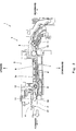
- FIG. 1 is a plan view showing a structure of an ink jet printer according to an embodiment of the present invention, a part of which, for example, a housing covering the entire ink jet printer is omitted;
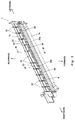
- FIG. 2 is a cross-sectional view of the ink-jet printer taken in the direction of arrows along line II-II in FIG. 1 , showing a structure of a recording unit;
- FIG. 3 is a perspective view of a platen with a platen cover attached thereon;
- FIG. 4 is a cross-sectional view of the platen taken in the direction of arrows along line IV-IV of FIG. 3 ;
- FIG. 5 is a block diagram showing a function of a part of the ink-jet printer, for moving up and down the recording unit in a configuration in which a control unit serves as a number counting unit;
- FIG. 6 is a flowchart showing an example of an operation performed by the ink jet printer to adjust a gap between a nozzle surface of the recording head and the platen;
- FIG. 7 is a flowchart showing a sub-routine associated with a maintenance process which is a part of the operation of FIG. 6 ;
- FIG. 8A is a block diagram showing a function of a part of the ink-jet printer, for moving up and down the recording unit in a configuration in which the control unit serves as a time measuring unit;
- FIG. 8B is a block diagram showing a function of a part of the ink-jet printer, for moving up and down the recording unit in a configuration in which the control unit serves as a scanning number counting unit.
- FIG. 1 is a plan view showing a structure of an ink jet printer according to an embodiment of the present invention, a part of which, for example, a housing covering the entire ink jet printer is omitted, for the sake of convenience of description.
- an ink jet printer 1 has a pair of right and left main frames 2 formed of metal plates or the like.
- a recording unit 3 is provided between the main frames 2 , for recording an image on recording paper (hereinafter referred to as paper) P which is being fed.
- paper recording paper
- the directions are referenced such that a feeding direction (direction indicated by a while arrow in FIG. 1 ) of the paper P on which an image is being recorded by the recording unit 3 is forward, and the other cases will be described appropriately.
- the recording unit 3 includes chassises 4 (indicated by two-dotted line in FIG. 1 ) arranged forward and rearward to bridge the main frames 2 .
- the chassises 4 are of a plate shape extending rightward and leftward.
- a carriage 5 (indicated by two-dotted line in FIG. 1 ) is supported to be slid able rightward and leftward on the front and rear chassises 4 which are guide rails.
- a recording head 6 (see FIG. 2 ) is accommodated in the carriage 5 .
- the carriage 5 is connected to a timing belt driven to move in a circumferential direction by a motor that is not shown.
- the carriage 5 is movable together with the recording head 6 in a longitudinal direction (rightward and leftward direction) of the chassises 4 according to an operation of the timing belt.
- a platen 7 which is elongated in the rightward and leftward direction as viewed from above, is disposed below the recording head 6 movable in this way.
- the ink jet printer 1 accommodates an ink cartridge (not shown) in a housing.
- the ink cartridge is connected to the carriage 5 through ink supply pipes (not shown) so that inks of respective colors of black, cyan, magenta, and yellow are independently supplied to the recording head 6 inside the carriage 5 .
- a control unit 40 (see FIG. 5 ) comprised of a CPU and others is accommodated in the housing.
- the control unit 40 is connected to the recording head 6 inside the carriage 5 via a flexible flat cable (not shown).
- the recording head 6 is capable of ejecting the inks of respective colors from nozzle holes based on a command signal from the control unit 40 .
- a waste ink receiver 30 is disposed on a right side of the platen 7 that is outside of a region where the paper P is fed, for receiving the ink discharged during a flushing operation performed by the recording head 6 .
- the recording head 6 is located above the waste ink receiver 30 and performs an ink discharge operation, i.e., a flushing operation in predetermined cycles during the recording operation, in order to prevent the nozzle holes from getting clogged with the ink.
- the waste ink receiver 30 receives the discharged ink.
- a left-side region of the platen 7 that is outside of the region where the paper P is fed is a stand-by position of the carriage 5 .
- a maintenance unit 31 for the recording head 6 is supported by the chassises 4 .
- the maintenance unit 31 maintains the recording head 6 by cleaning a nozzle surface 6 a (see FIG. 2 ) of the recording head 6 in the stand-by position by using a blade made of rubber or the like to remove adhering substances or matters and by selectively suctioning inks of the respective colors to prevent the nozzle holes from getting clogged with the ink.
- FIG. 2 is a cross-sectional view of the ink-jet printer taken in the direction of arrows along line II-II in FIG. 1 , showing a structure of the recording unit 3 .
- the ink jet printer 1 includes a pair of upper and lower resist rollers 10 disposed behind the platen 7 , and a detection lever 11 disposed behind the resist rollers 10 for detecting a tip end of the paper P.
- the ink jet printer 1 according to the embodiment includes a cassette (not shown) disposed below the platen 7 for accommodating a number of sheets of paper P. The sheets of paper P inside the cassette are fed to the resist rollers 10 by a known feeding means via the detection lever 11 .
- the detection lever 11 is disposed to cross a feeding path of the paper P.
- the detection lever 11 is retractable outside of the feeding path of the paper P when a tip end of the paper P contacts the detection lever 11 .
- a sensor 11 a detects this, and outputs a signal indicating this to a control unit 40 .
- the control unit 40 measures a time that lapses immediately after receiving the signal. After a lapse of a specified time, the control unit 40 outputs a signal to the recording head 6 to cause the ink to be ejected from the nozzle holes.
- the resist rollers 10 are disposed with their rotational axes oriented in the rightward and leftward direction.
- the paper P that has been fed via the detection lever 11 is trapped into between the upper and lower resist rollers 10 and is fed further forward by the resist rollers 10 .
- the paper P fed forward by the resist rollers 10 is guided into a space defined by the recording head 6 and the platen 7 with the paper P supported from a rear surface (lower surface) side by the platen 7 , and recording is performed on a surface of the paper P in this space.
- the platen cover 8 that is formed of a plate elongated in the rightward and leftward direction is provided above a front portion of the platen 7 .
- a spur roller 12 having a rotational axis extending in the rightward and leftward direction is mounted above the platen cover 8 .
- the spur roller 12 contacts the surface (upper surface) of the paper P being fed along the upper surface of the platen 7 and the upper surface of the platen cover 8 , thereby preventing the paper P being subjected to recording from being displaced upward from the upper surface of the platen 7 .
- a spur roller 13 and a paper discharging roller 14 are disposed in upper and lower positions forward of the platen 7 .
- the rollers 13 and 14 are disposed with their rotational axes oriented in the rightward and leftward direction.
- the spur roller 13 and the paper discharging roller 14 rotate while trapping between the rollers 13 and 14 the paper P that has gone through recording on the platen 7 to guide the paper P that has gone through recording to an outlet (not shown) of the ink jet printer 1 .
- an eccentric cam 17 a forming a gap adjustment mechanism 17 is mounted in contact with a lower surface of the front chassis 4 under the front chassis 4 .
- the eccentric cam 17 a is connected via a gear to an output shaft of a motor 17 b driven in accordance with a command from the control unit 40 .
- the eccentric cam 17 a rotates to vertically move the carriage 5 including the recording head 6 together with the chassis 4 closer to and away from the platen 7 so that a gap d between the recording head 6 and the platen 7 is adjusted as desired in a range between a distance d 1 and a distance d 2 .
- the gap d between the recording head 6 and the platen 7 is set to the distance d 1 to improve adhesion position precision of ink ejected from the recording head 6 .
- the gap d can be set to a distance d 3 ( ⁇ d 2 ) that is larger than the distance d 1 to protect the nozzle surface 6 a from contact with the paper P, or otherwise to the distance d 2 larger than the distance d 3 as desired.
- FIG. 3 is a perspective view of the platen 7 with the platen cover 8 attached thereon.
- FIG. 4 is a cross-sectional view of the platen 7 taken in the direction of arrows along line IV-IV of FIG. 3 .
- the platen 7 is a member that is made of synthetic resin and is of a substantially box shape elongated in the rightward and leftward direction as viewed from above.
- a front portion of the platen 7 forms an ink reservoir 7 a for reserving excess ink that has not adhered to the paper P, and a rear portion thereof forms a paper support portion 7 b for supporting the paper P from the rear surface side.
- the platen cover 8 covers the ink reservoir 7 a of the platen 7 from above (see FIG. 2 ).
- the platen 7 includes a platen body 20 and a plurality of upstream ribs 22 that are provided above the platen body 20 (closer to the recording head 6 or the paper P being subjected to recording than the platen body 20 , for supporting the paper P from the rear surface side.
- the upstream ribs 22 are provided to extend upward on the platen body 20 .
- the platen body 20 is provided at a rear portion thereof with a concave plate portion 23 recessed downward.
- a shelf plate portion 24 of a flat plate shape is provided to extend forward continuously from the concave plate portion 23 such that the shelf plate portion 24 is opposite to a rear surface of the paper P.
- An upper surface of the shelf plate portion 24 is located higher than an inner bottom surface of the concave plate portion 23 .
- the upstream ribs 22 are provided to extend from the concave plate portion 23 to the shelf plate portion 24 .
- the upstream ribs 22 are plate shaped, and are arranged at constant intervals (intervals of about 20 mm in this embodiment) from a left end to a right end of the platen body 20 . As shown in FIG. 4 , the upstream ribs 22 are provided to extend upward from the inner bottom surface 23 a of the concave plate portion 23 and from the upper surface 24 a of the shelf plate portion 24 , and from a rear end portion of the concave plate portion 23 to a front end portion of the shelf plate portion 24 in the feeding direction of the paper P.
- Spaces 22 b are formed between upper end portions (contact portions) 22 a of adjacent upstream ribs 22 so as to expose the surface of the platen body 20 , and thus, only the upper end portions (contact portions) 22 a of the upstream ribs 22 directly contact the paper P from the rear surface side to support the paper P at a rear portion of the platen body 20 .
- An adhesive layer 25 made of a specified adhesive is provided on the surface of the platen body 20 that is opposite to the paper P with the spaces 22 b formed there between, i.e., the inner bottom surface 23 a of the concave plate portion 23 and the upper surface 24 a of the shelf plate portion 24 .
- the upstream ribs 22 , the concave plate portion 23 and the shelf plate portion 24 of the platen body 20 , and the adhesive layer 25 form the paper support portion 7 b of the platen 7 .
- An ink receiver 26 of a flat plate shape is provided at a front portion of the platen body 20 so as to extend forward continuously from the shelf plate portion 24 .
- a concave ink recovery unit 27 that is recessed downward is provided in front of the ink receiver 26 to extend continuously from the ink receiver 26 .
- the ink receiver 26 has an upper surface 26 a that is slightly inclined downward in the forward direction.
- a plurality of downstream ribs 28 are provided to extend upward on the upper surface 26 a of the ink receiver 26 and in the feed direction of the paper P, i.e., forward and rearward.
- the downstream ribs 28 are arranged in the rightward and leftward direction at constant intervals smaller than those of the upstream ribs 22 (see FIG. 3 ).
- a porous ink absorbing element 29 capable of absorbing ink is provided on the inner bottom surface 27 a of the ink recovery unit 27 .
- the ink receiver 26 , the ink recovery unit 27 , the downstream ribs 28 , and the ink absorbing element 29 form the ink reservoir 7 a of the platen 7 .
- the adhesive layer 25 provided on the upper surface of the platen 7 captures the paper powder generated from the paper P. Since the adhesive layer 25 is provided on the surface of the platen 7 that is opposite to the recording head 6 , i.e., the inner bottom surface 23 a of the concave plate portion 23 and the upper surface 24 a of the shelf plate portion 24 , in a location below the upstream ribs 22 that directly contact the paper P, it can capture the paper powder efficiently.
- the adhesive layer 25 is provided on the inner bottom surface 23 a of the concave plate portion 23 and the upper surface 24 a of the shelf plate portion 24 , it is not intended to be limited to this.
- the adhesive layer 25 may be provided on a front vertical wall surface 23 b (see FIG. 4 ) connecting the inner bottom surface 23 a of the concave plate portion 23 to the upper surface 24 a of the shelf plate portion 24 , or a rear vertical wall surface 23 c (see FIG. 4 ) of the concave plate portion 23 that is opposite to the front vertical wall surface 23 b .
- the adhesive layer 25 may be provided on right and left surfaces of the upstream ribs 22 .
- the platen 7 has the ink reservoir 7 a .
- excess ink remaining unadhered onto the paper P when so-called edgeless printing is carried out is guided to the ink recovery unit 27 through grooves formed between adjacent downstream ribs 28 and is absorbed in the ink absorbing element 29 . This makes it possible to prevent the excess ink from contaminating the paper P.
- the ink jet printer 1 includes the control unit 40 comprised of the CPU, the memories, and others.
- the control unit 40 operates according to programs stored in the memory to serve as a number counting unit 41 for counting the number of papers P subjected to recording, which is a value indicating recording amount of the paper P.
- control unit 40 when the control unit 40 operates according to the flowchart of FIG. 6 described later, it operates as the number counting unit 41 in step S 15 . Also, when the control unit 40 serves as a time measuring unit 42 or a scanning number counting unit 43 , it measures a recording operation time or counts the scanning number based on a signal output from the control unit 40 to the recording unit 6 via the flexible flat cable.
- the motor 17 b forming the gap adjustment mechanism 17 is connected to the control unit 40 via a drive circuit (not shown).
- the motor 17 b rotates the output shaft by a specified rotational angle based on a command signal from the control unit 40 so that the gap d between the nozzle surface 6 a of the recording head 6 and the platen 7 is set between the distance d 1 and the distance d 2 .
- the gap d is, as shown in FIG. 2 , a distance from the contact portions 22 a of the upstream ribs 22 of the platen 7 to the nozzle surface 6 a.
- the control unit 40 controls operation of the other parts in the ink jet printer 1 .
- the control unit 40 is communicatively coupled to the sensor 11 a for detecting the tip end of the paper P and decides the recording operation to be performed on the paper P at a timing based on a signal from the sensor 11 a .
- the control unit 40 controls the operation of the ink jet printer 1 , such as the flushing operation in the waste ink receiver 30 or the maintenance process in the maintenance unit 31 .
- FIG. 6 is a flowchart showing an example of an operation performed by the ink-jet printer 1 to adjust the gap d between the nozzle surface 6 a of the recording head 6 and the platen 7 .
- FIG. 7 is a flowchart showing a sub-routine associated with the maintenance process which is a part of the operation of FIG. 6 .
- the control unit 40 operates as the number counting unit 41 as described below.
- a power supply of the ink jet printer 1 is turned on (S 1 ).
- the control unit 40 initializes the gap d between the nozzle surface 6 a of the recording head 6 and the platen 7 to a preset reference gap d 0 (S 2 ).
- the reference gap d 0 can be set between the distance d 1 and the distance d 2 as desired.
- the control unit 40 determines whether or not there is a recording command, i.e., a command for recording operation, to be specific, whether or not an operator has operated an input panel or the like suitably provided on the ink jet printer 1 , or there is a command from a computer communicatively coupled to the ink jet printer 1 (S 3 ).
- control unit 40 determines that there is no recording command (S 3 : NO), it repeats an operation in step S 3 . On the other hand, if the control unit 40 determines that there is a recording command (S 3 : YES), it transitions to the maintenance process (S 4 ).
- the control unit 40 obtains a time T that lapses from a previous maintenance process (S 41 ). To be specific, first, the control unit 40 reads in from the memory therein, the time T that has lapsed from the completion of the previous maintenance process for the recording head 6 performed by the maintenance unit 31 . The control unit 40 determines whether or not the time T is larger than a preset time value T 1 (S 42 ). If the control unit 40 determines that the time T is larger than the preset time value T 1 (S 42 : YES), it outputs a command signal to the maintenance unit 31 to cause the maintenance unit 31 to carry out the maintenance operation on the nozzle surface 6 a of the recording head 6 (S 43 ).
- the maintenance operation means a cleaning operation performed on the nozzle surface 6 a of the recording head 6 in such a manner that inks of respective colors are suctioned through the nozzle holes or contamination is removed from the nozzle surface 6 a by using a blade or the like.
- control unit 40 After carrying out the maintenance operation, the control unit 40 resets the time T stored in the memory to zero, and resets to zero a recording number N stored in the memory, relating to the recording number after the maintenance process (S 44 ).
- the control unit 40 starts measuring the lapse time T again (S 45 ) and terminates the sub-routine associated with the maintenance process. If the control unit 40 determines that the lapse time T is not larger than the preset time value T 1 (S 42 : NO) in step S 42 , it also terminates the sub-routine associated with the maintenance process.
- the control unit 40 After finishing the sub-routine associated with the maintenance process, the control unit 40 obtains the recording number N stored in the memory (S 5 ), and then selects a recording mode to be executed (S 6 ).
- a recording mode As the recording mode, a fineness mode which is the recording mode for the photo image quality, and a normal mode which is the recording mode for printing to create documents are set.
- control unit 40 determines whether or not the recording number N obtained in step S 5 is larger than a predetermined value N 1 (S 7 ). If the control unit 40 determines that the recording number N obtained in step S 5 is not larger than the predetermined value N 1 (S 7 : NO), it sets the gap d to the distance d 1 for the recording in the fineness mode (S 8 ).
- control unit 40 determines that the recording number N obtained in step S 5 is larger than the predetermined value N 1 (S 7 : YES), it rotates the motor 17 b to drive the gap adjustment mechanism 17 so that the gap d is set to a distance (d 1 + ⁇ ) that is larger than the distance d 1 (d 1 + ⁇ d 2 ) (step S 9 ). Under this condition, the recording operation is carried out (S 13 ).
- the term “recording operation” refers to one scanning which is a reciprocating operation of the recording head 6 along the chassises 4 .
- control unit 40 determines whether or not the recording number N obtained in step S 5 is larger than a predetermined value N 1 (S 10 ). If the control unit 40 determines that the recording number N is not larger than N 1 (S 10 : NO), it sets the gap d to the distance d 3 (d 3 >d 1 ) for recording in the normal mode (S 11 ).
- control unit 40 determines that the recording number N is larger than N 1 (S 10 : YES)
- it rotates the motor 17 b to drive the gap adjustment mechanism 17 so that the gap d is set to a distance (d 3 +a) that is larger than the distance d 3 (d 3 +a ⁇ d 2 ) (step S 12 ).
- the recording operation is carried out (S 13 ).
- the control unit 40 determines whether or not recording of one sheet of paper P is complete, based on a signal indicating a recording content output from the control unit 40 to the recording head 6 or a detection signal from the sensor 11 a (S 14 ).
- step S 14 If the control unit 40 determines that recording of one sheet of paper P is complete in step S 14 (S 14 : YES), the control unit 40 adds one to the value of the recording number N stored in the memory (S 15 ). If the control unit 40 determines that recording of one sheet of paper P is not complete yet (S 14 : NO), it keeps the recording number N stored in the memory as it is. After the control unit 40 determines that recording of one sheet of paper P is not complete yet (S 14 : NO), and performs step S 15 , it further determines whether or not the operation based on the recording command received in step S 13 is complete (S 16 ).
- control unit 40 determines that the operation based on the recording command is complete (S 16 : YES), it executes the operation in step S 3 and the following steps. On the other hand, if the control unit 40 determines that the operation based on the recording command is not complete yet (S 16 : NO), it executes the operation in step S 4 and the following steps. In step S 15 , the control unit 40 operates as the number counting unit 41 .
- the control unit 40 changes the gap d to the gap larger than the gap d (e.g., d 1 + ⁇ , d 3 + ⁇ : second gap) (step S 9 and S 12 ), if the control unit 40 determines that the recording number N is larger than the predetermined value N 1 in the following routine (S 7 and S 10 : YES). After changing the gap d, adhesion of the paper powder onto the nozzle surface 6 a of the recording head 6 can be suppressed.
- the gap d is adjusted based on the value of the recording number N
- the gap d may be adjusted based on the operation time T of the recording head 6 after the previous maintenance process.
- a function of a part of the above described ink jet printer 1 , for moving up and down the recording head 6 is configured as illustrated in FIG. 8A , showing that the time measuring unit 42 replaces the number counting unit 41 shown in FIG. 5 .
- the control unit 40 reads in the time T instead of the recording number N in step S 5 in the flowchart of FIG. 6 , and determines whether or not the time T is larger than a predetermined value T 2 (T 2 ⁇ T 1 ) in step S 7 and S 10 .
- steps 14 and 15 may be omitted.
- the gap d may be adjusted based on the number of scanning performed by the recording head 6 after the previous maintenance process.
- a function of a part of the ink jet printer 1 , for moving up and down the recording head 6 is configured as illustrated in FIG. 8B , showing that the scanning number counting unit 43 replaces the number counting unit 41 shown in FIG. 5 .
- the control unit 40 executes the steps along the flowchart of FIG. 6 in which the recording number has been replaced by the scanning number. Also, the steps S 14 and S 15 may be omitted.
- the control unit 40 may be configured to be able to execute any ones of the number counting unit 41 , the time measuring unit 42 , and the scanning number measuring unit 43 .
- the platen 7 may be configured to be movable close to and away from the recording head 6 , or both of the platen 7 and the recording head 6 may be configured to be movable relatively to be close to and away from each other.
- the recording unit 3 has the recording head 6 mounted to the carriage 5
- the present invention is not intended to be limited to this configuration.
- the recording unit may include a recording head which has nozzle rows that are formed by a plurality of nozzle holes arranged in the width direction of the paper P and that extend longer than the width of the paper P, and which is configured not to be movable in the width direction of the paper P. That is, the recording unit may include so-called a line-type recording head.
Landscapes
- Ink Jet (AREA)
- Handling Of Sheets (AREA)
Abstract
Description
Claims (9)
Applications Claiming Priority (2)
| Application Number | Priority Date | Filing Date | Title |
|---|---|---|---|
| JP2006272807A JP2008087400A (en) | 2006-10-04 | 2006-10-04 | Recording device |
| JP2006-272807 | 2006-10-04 |
Publications (2)
| Publication Number | Publication Date |
|---|---|
| US20080136850A1 US20080136850A1 (en) | 2008-06-12 |
| US7806494B2 true US7806494B2 (en) | 2010-10-05 |
Family
ID=39372034
Family Applications (1)
| Application Number | Title | Priority Date | Filing Date |
|---|---|---|---|
| US11/906,617 Expired - Fee Related US7806494B2 (en) | 2006-10-04 | 2007-10-03 | Recording apparatus |
Country Status (2)
| Country | Link |
|---|---|
| US (1) | US7806494B2 (en) |
| JP (1) | JP2008087400A (en) |
Families Citing this family (3)
| Publication number | Priority date | Publication date | Assignee | Title |
|---|---|---|---|---|
| JP4991906B2 (en) * | 2010-05-06 | 2012-08-08 | キヤノン株式会社 | Recording device |
| WO2020185227A1 (en) * | 2019-03-13 | 2020-09-17 | Hewlett-Packard Development Company, L.P. | Printers |
| JP7309402B2 (en) * | 2019-03-26 | 2023-07-18 | 理想科学工業株式会社 | image forming device |
Citations (4)
| Publication number | Priority date | Publication date | Assignee | Title |
|---|---|---|---|---|
| US5291227A (en) | 1991-05-17 | 1994-03-01 | Ricoh Company, Ltd. | Ink jet printer having improved paper transport mechanism |
| US5608430A (en) * | 1994-03-07 | 1997-03-04 | Tektronix, Inc. | Printer print head positioning apparatus and method |
| US6315468B2 (en) * | 1997-01-30 | 2001-11-13 | Seiko Epson Corporation | Ink jet recording apparatus with a platen gap regulator |
| JP2003034057A (en) | 2001-07-23 | 2003-02-04 | Olympus Optical Co Ltd | Image recorder |
-
2006
- 2006-10-04 JP JP2006272807A patent/JP2008087400A/en active Pending
-
2007
- 2007-10-03 US US11/906,617 patent/US7806494B2/en not_active Expired - Fee Related
Patent Citations (4)
| Publication number | Priority date | Publication date | Assignee | Title |
|---|---|---|---|---|
| US5291227A (en) | 1991-05-17 | 1994-03-01 | Ricoh Company, Ltd. | Ink jet printer having improved paper transport mechanism |
| US5608430A (en) * | 1994-03-07 | 1997-03-04 | Tektronix, Inc. | Printer print head positioning apparatus and method |
| US6315468B2 (en) * | 1997-01-30 | 2001-11-13 | Seiko Epson Corporation | Ink jet recording apparatus with a platen gap regulator |
| JP2003034057A (en) | 2001-07-23 | 2003-02-04 | Olympus Optical Co Ltd | Image recorder |
Also Published As
| Publication number | Publication date |
|---|---|
| JP2008087400A (en) | 2008-04-17 |
| US20080136850A1 (en) | 2008-06-12 |
Similar Documents
| Publication | Publication Date | Title |
|---|---|---|
| JP4948146B2 (en) | Inkjet recording device | |
| US8619270B2 (en) | Double-side recording apparatus and recording method | |
| CN1295081C (en) | Image forming device and recovery jet method for printing head | |
| CN101844444B (en) | Inkjet recording device | |
| JP7676616B2 (en) | Recording device, control method, and program | |
| CN110712428B (en) | Inkjet recording device | |
| JP3161534B2 (en) | Ink jet recording device | |
| JP4208539B2 (en) | Inkjet recording device | |
| US6352333B2 (en) | Method and apparatus for preventing nozzle clogging in ink jet printing apparatus | |
| JP2002154200A (en) | Image forming device | |
| JP3970097B2 (en) | Recording device | |
| US7806494B2 (en) | Recording apparatus | |
| WO2002014074A1 (en) | Ink-jet recorder and method for cleaning restoring system | |
| JP2009119652A (en) | Image forming apparatus | |
| US20040109050A1 (en) | Ink-jet image forming apparatus | |
| EP1693211B1 (en) | Method of controlling liquid ejection | |
| JPH0952374A (en) | Inkjet recording device | |
| JP4614600B2 (en) | Inkjet recording device | |
| JP5252210B2 (en) | Transfer material cutting apparatus and image forming apparatus | |
| JP4630558B2 (en) | Recording apparatus and recovery control method | |
| JPH06328731A (en) | Ink jet recording device | |
| JP3922222B2 (en) | Liquid ejection apparatus and control method thereof | |
| JP2003054052A (en) | Inkjet printer | |
| JP2002029039A (en) | Ink jet recorder and method for ink jet recording | |
| JP2025110520A (en) | Liquid discharge device, liquid discharge method |
Legal Events
| Date | Code | Title | Description |
|---|---|---|---|
| AS | Assignment |
Owner name: BROTHER KOGYO KABUSHIKI KAISHA, JAPAN Free format text: ASSIGNMENT OF ASSIGNORS INTEREST;ASSIGNOR:SHINDO, TATSUYA;REEL/FRAME:020580/0789 Effective date: 20080207 |
|
| STCF | Information on status: patent grant |
Free format text: PATENTED CASE |
|
| FPAY | Fee payment |
Year of fee payment: 4 |
|
| MAFP | Maintenance fee payment |
Free format text: PAYMENT OF MAINTENANCE FEE, 8TH YEAR, LARGE ENTITY (ORIGINAL EVENT CODE: M1552) Year of fee payment: 8 |
|
| FEPP | Fee payment procedure |
Free format text: MAINTENANCE FEE REMINDER MAILED (ORIGINAL EVENT CODE: REM.); ENTITY STATUS OF PATENT OWNER: LARGE ENTITY |
|
| LAPS | Lapse for failure to pay maintenance fees |
Free format text: PATENT EXPIRED FOR FAILURE TO PAY MAINTENANCE FEES (ORIGINAL EVENT CODE: EXP.); ENTITY STATUS OF PATENT OWNER: LARGE ENTITY |
|
| STCH | Information on status: patent discontinuation |
Free format text: PATENT EXPIRED DUE TO NONPAYMENT OF MAINTENANCE FEES UNDER 37 CFR 1.362 |
|
| FP | Lapsed due to failure to pay maintenance fee |
Effective date: 20221005 |